iPhone X Power and Audio Exterior Buttons Replacement
The external housing's buttons consist of the Power/Lock Button, Volume Buttons, and the Vibrate/Ring Switch. This repair manual details the procedure for substituting buttons exhibiting superficial defects.
The instructions presented here are largely adapted from a video created by iPhoneRepairGirl which provides a detailed demonstration of removing and replacing the power and volume buttons; recognition is given to her for the initial discovery and public sharing of this method. A reference to her video can be found at:
iPhone X Side Button Replacement Tutorial - DIY Pro Tips - Repair With Me - YouTube
Step 1 | SIM Card


- To begin, slide a SIM card eject tool, or a straightened paperclip, into the tiny aperture situated on the SIM card tray, which is positioned close to the side button along the iPhone's edge.Apply consistent pressure to release the tray from its slot.
- The tray will then pop out.
Step 2
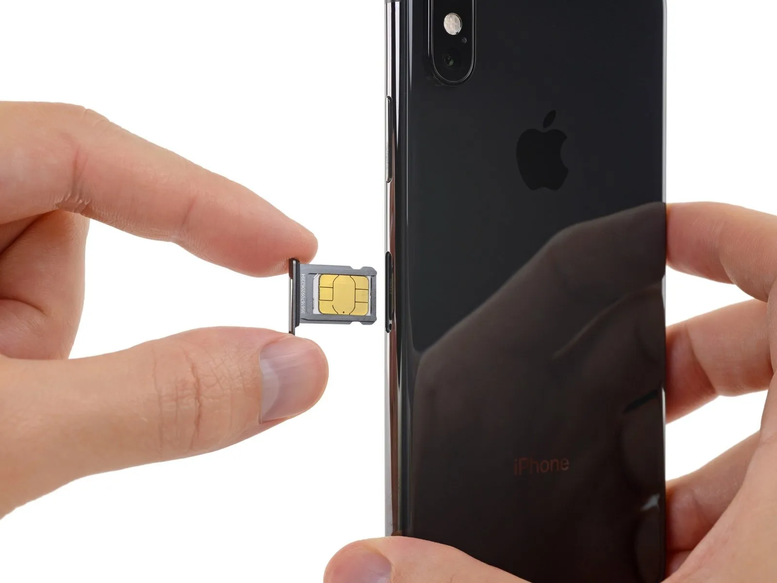

- Extract the SIM card tray from the iPhone's housing.
- The SIM card should detach from the tray with minimal effort.
- During the process of placing the SIM card back into the tray, confirm its alignment matches the tray's design.
- A flexible, rubber seal encircles the SIM tray, offering defense against water and dust intrusion; should this seal become compromised or absent, substitute it or the SIM tray assembly to safeguard the iPhone's internal electronics.
Step 3 | Pentalobe Screws
As a preliminary safety measure, ensure your iPhone's battery is depleted to a level below 25%; a fully charged lithium-ion battery presents a fire or explosion hazard if it sustains accidental physical damage.
To ensure safety and prevent short circuits, completely de-energize the iPhone prior to commencing the disassembly process.
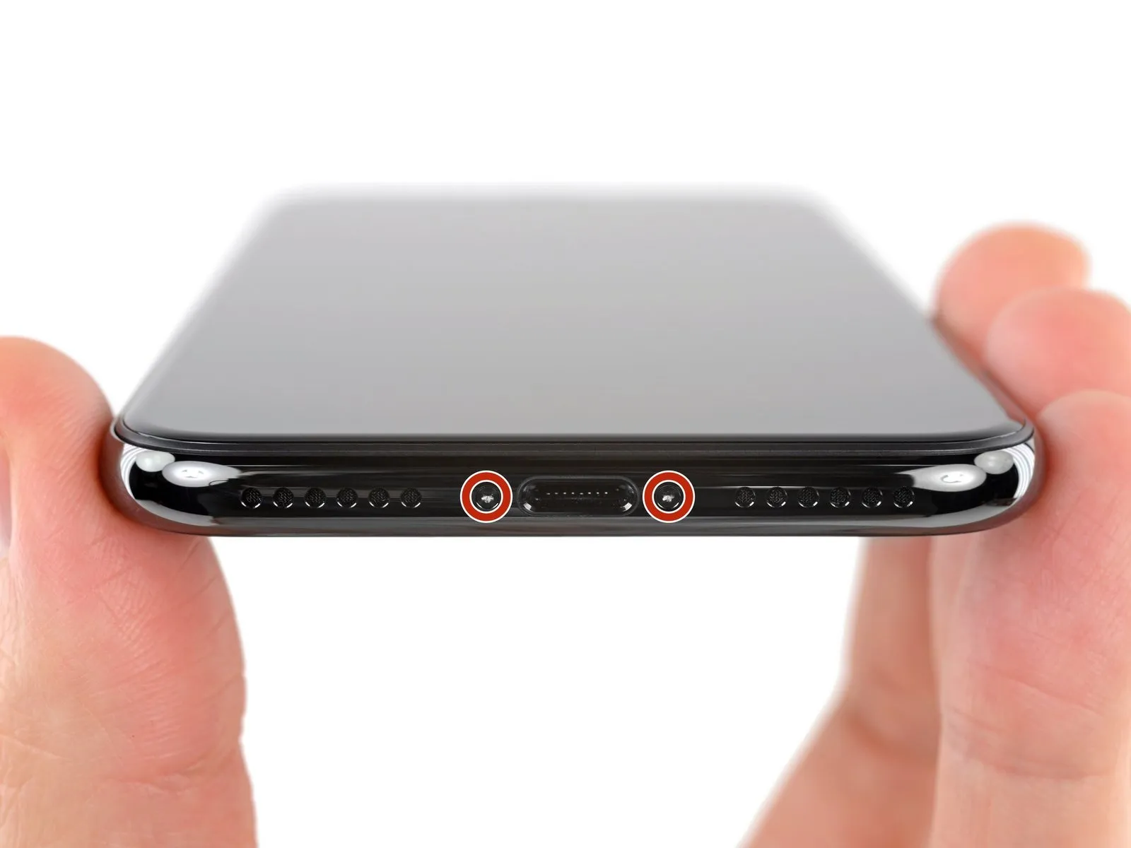
Begin by removing thetwo pentalobe screws, each measuring 6.9 mm in length,which are located along the iPhone's lower edge.
- Should the screws exhibit signs of damage or stripping, it is necessary to substitute them with replacements.
Disassembly of the iPhone's display assembly will inevitably damage the integrated waterproof seals; therefore, prepare replacement seals beforehand, or exercise extreme caution to prevent moisture ingress if you intend to reassemble the iPhone without new seals.
Step 4 | Mark your opening picks


To avoid potential harm to your device, ensure the opening pick does not penetrate excessively; this procedure details how to identify a safe insertion depth by marking the pick.
Determine3 mmfrom the pick's distal end, and use a permanent marker to create a visible indicator on the opening pick.
For enhanced precision, consider marking additional points on the pick's corners with varying measurements.
As an alternative method, affix a coin to the pick's tip, positioning it precisely 3 mm from the distal end.
Step 5 | Tape over any cracks


- To mitigate additional damage and potential injury while repairing an iPhone with a cracked display, secure the fractured glass with adhesive tape.
Apply successive layers of transparent packing tape across the iPhone's screen surface, ensuring complete coverage of the front face. - Always utilize safety eyewear to guard against glass fragments that may become dislodged during the repair process.
- Should the suction cup fail to adhere adequately in subsequent procedures, create a handle by folding a durable tape, like duct tape, and employ it to gently raise the screen.
- As a last resort, secure the suction cup to the screen's surface using superglue.
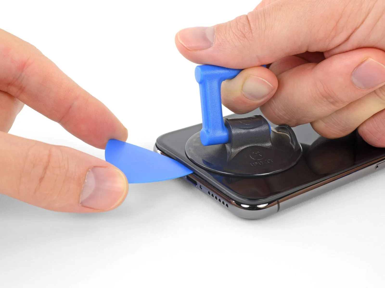
Step 6 | Anti-Clamp instructions


Detailed guidance regarding the Anti-Clamp's operation can be found in a separate instructional document.
- To release the Anti-Clamp's gripping arms, move the blue handle in a rearward direction.
- Position the arms across either the left or right side of your iPhone.
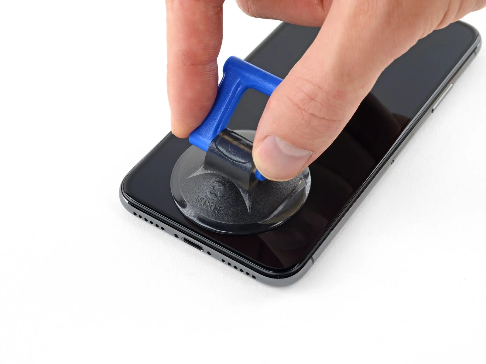
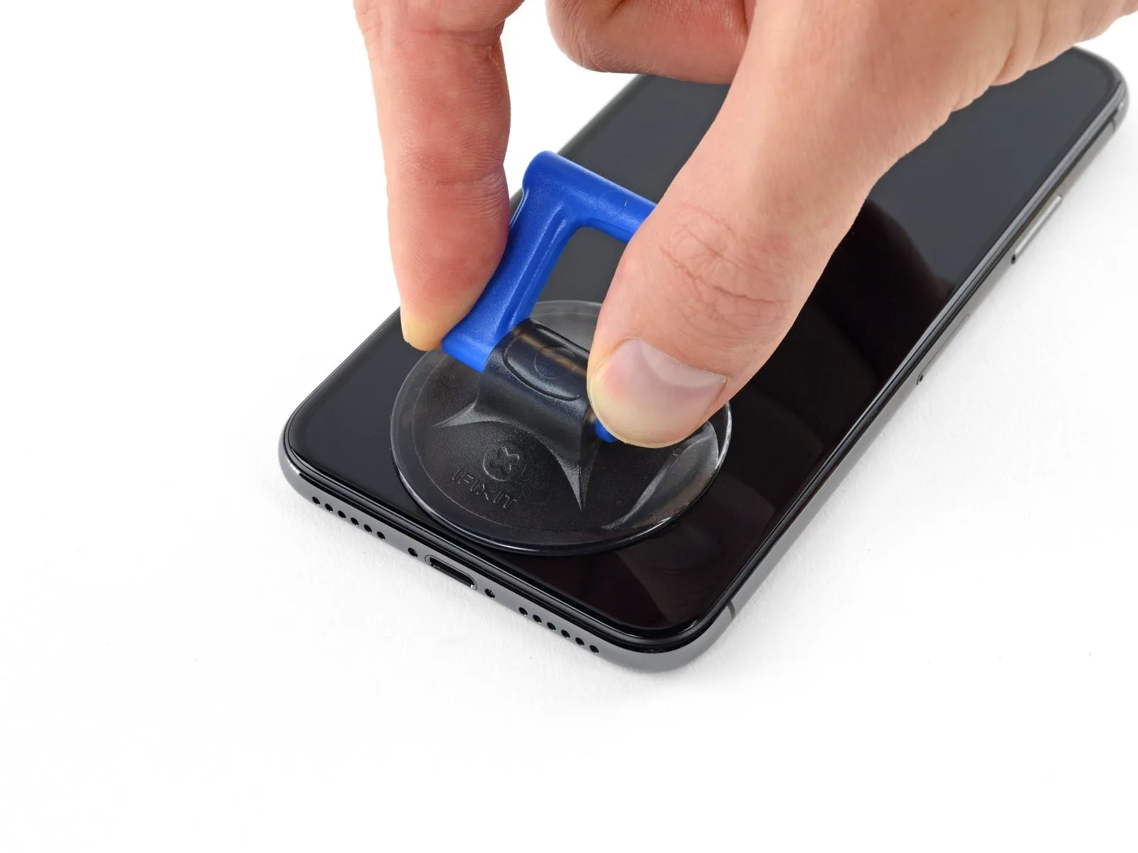
- Place the suction cups close to the lower edge of the iPhone, ensuring one is situated on the front surface and the other on the rear.
- Apply pressure by compressing the cups together to establish a secure suction hold on the intended location.
- Should the iPhone's surface prove excessively slick, preventing the Anti-Clamp from maintaining a firm grip, applying adhesive tape can enhance surface friction.
Step 7


Rotate the handle a full 360-degree circle, or continue turning until the suction cups exhibit signs of deformation.
Maintain the parallel positioning of the suction cups; should they deviate from their alignment, marginally reduce the suction cup's grip and reposition the arms.
Step 8


Alternative heat sources, such as a hair dryer, heat gun, or hot plate, may be utilized; however, excessive heat poses a risk of damage to the display assembly and/or the internal battery, necessitating cautious operation.
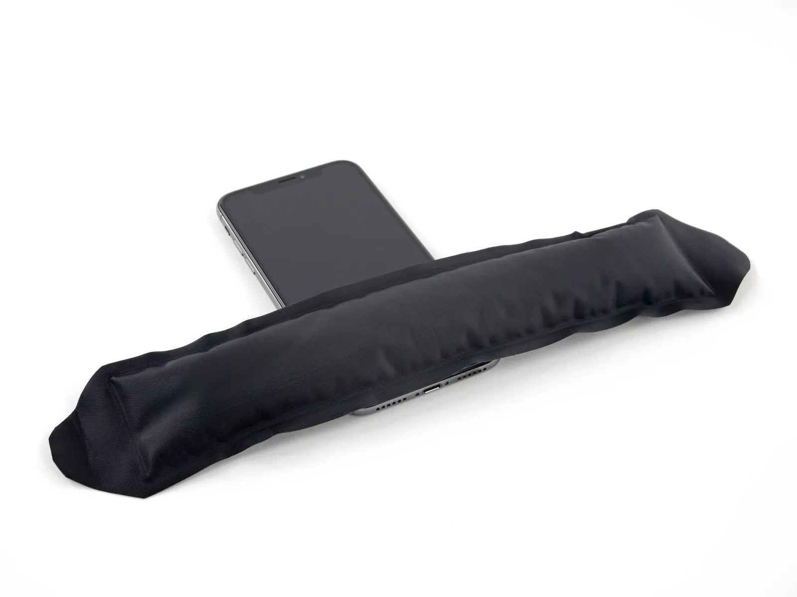
- Position the iOpener so that it rests along the lower edge of the iPhone’s casing by folding it.
- Allow a period of sixty seconds to elapse, enabling the adhesive to loosen and create a separation.
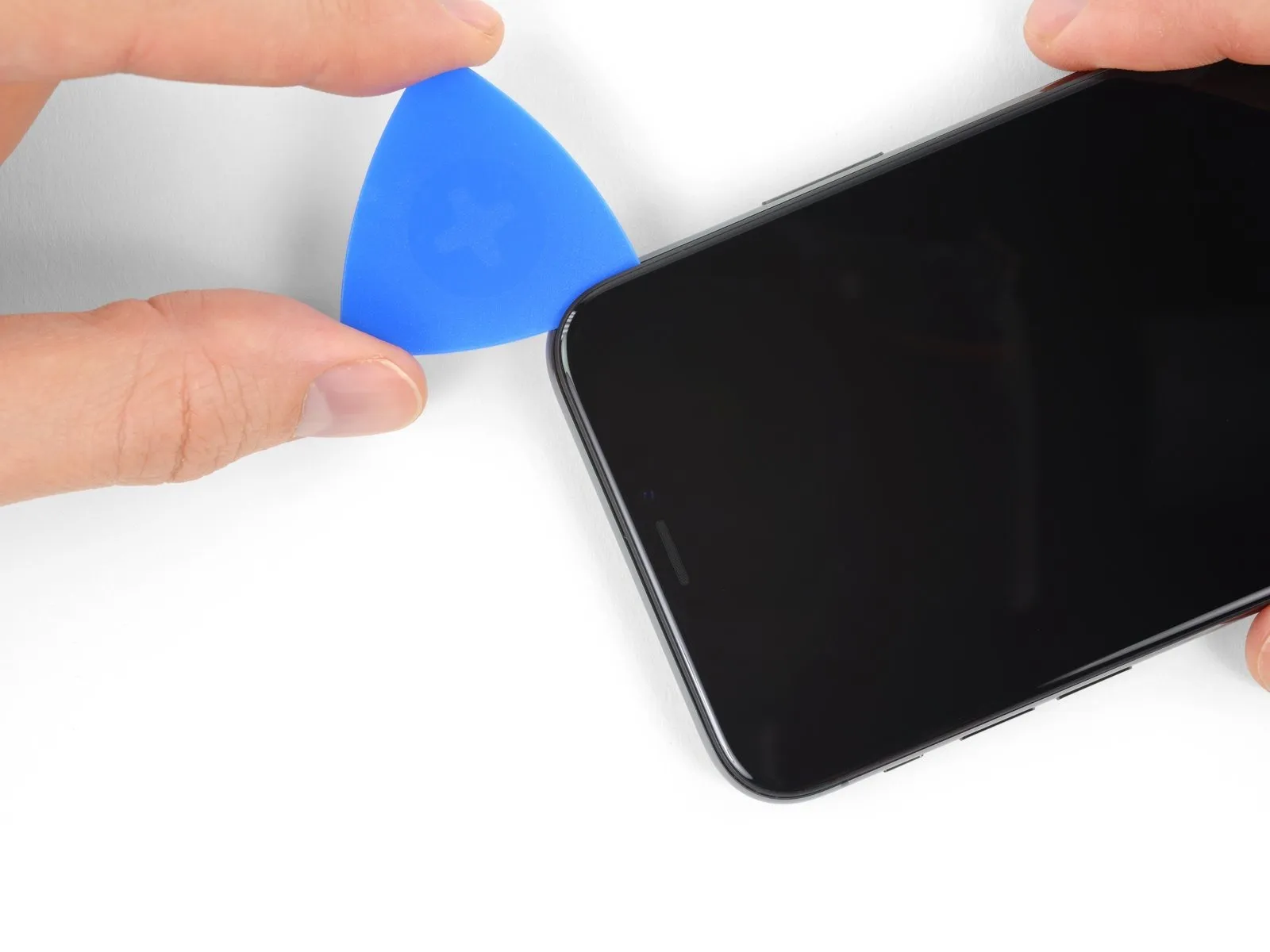
- Introduce an opening pick beneath the display surface and the surrounding plastic bezel, ensuring it does not contact the screen directly.
- Should the Anti-Clamp not generate a satisfactory separation, increase the heat applied to the region and rotate the handle by ninety degrees.
- Avoid rotating the handle beyond a ninety-degree increment at any point, and observe a sixty-second interval between rotations; allow the Anti-Clamp and time to facilitate the separation process.
Step 9
- Employing a hairdryer, heat gun, or iOpener, direct it towards the lower edge of the iPhone for approximately one minute to reduce the adhesive's tackiness.
- When utilizing a hairdryer or heat gun, avoid excessive heat application, as this could potentially harm the display.
Step 10
Step 11
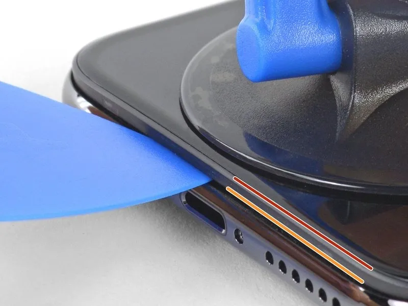
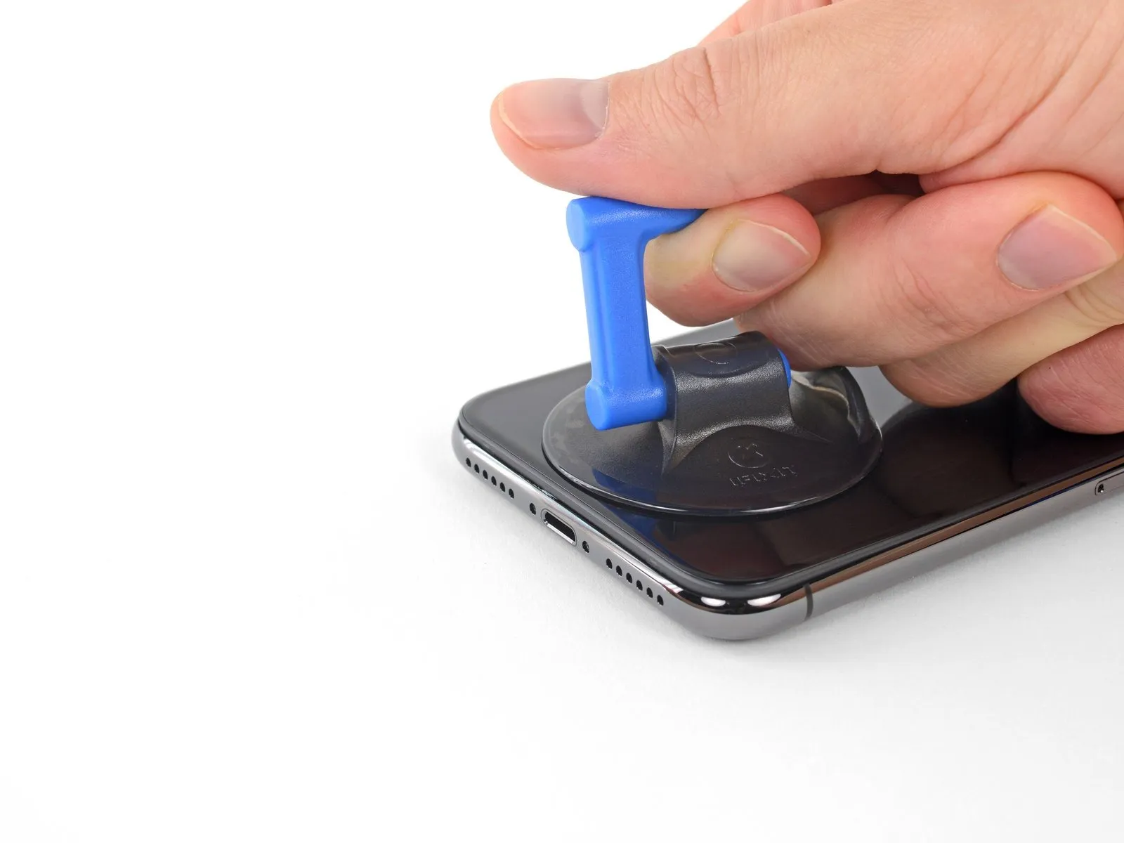
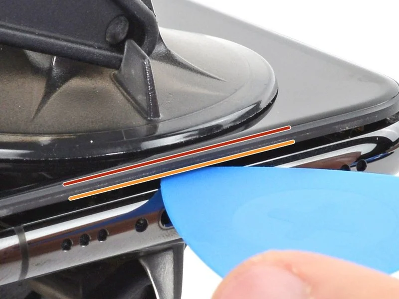
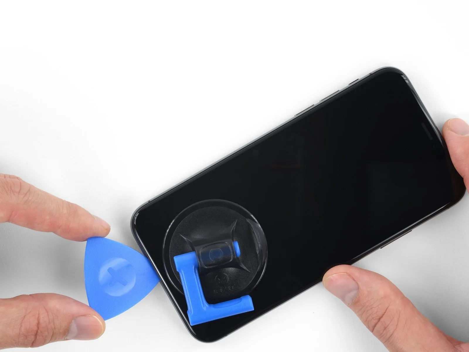
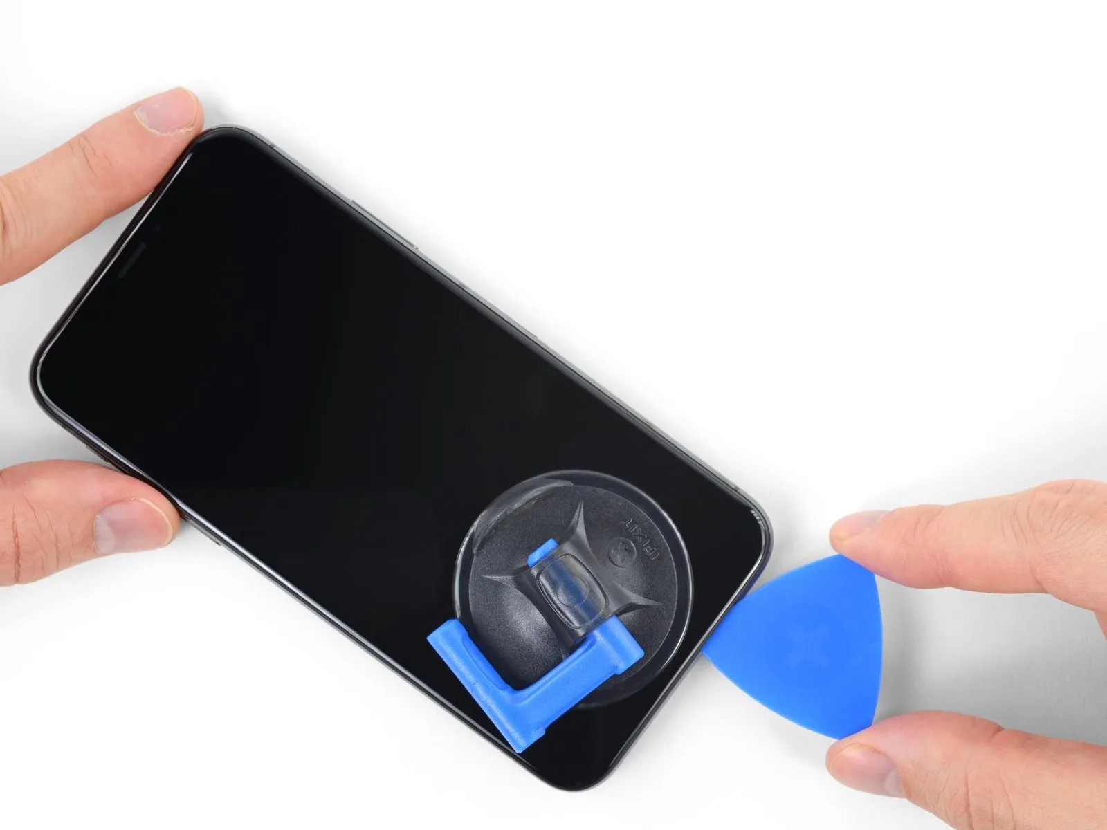
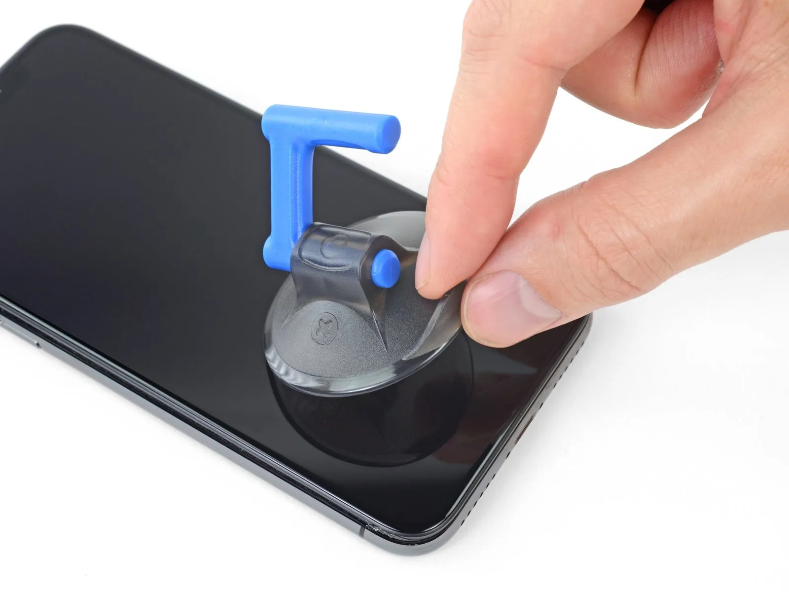
- Maintain consistent, forceful upward traction on the suction cup to generate a small separation between the display assembly and the device's chassis.
- Carefully slide an opening tool into the created space, positioning it beneath the plastic frame surrounding the display, ensuring it does not contact the display panel itself.
- Due to the robust, waterproof adhesive securing the display, a considerable amount of force may be necessary to initially separate the components; if encountering difficulty, apply additional heat and gently oscillate the display upward and downward to reduce the adhesive's strength until a sufficient gap is achieved for tool insertion.
Step 12
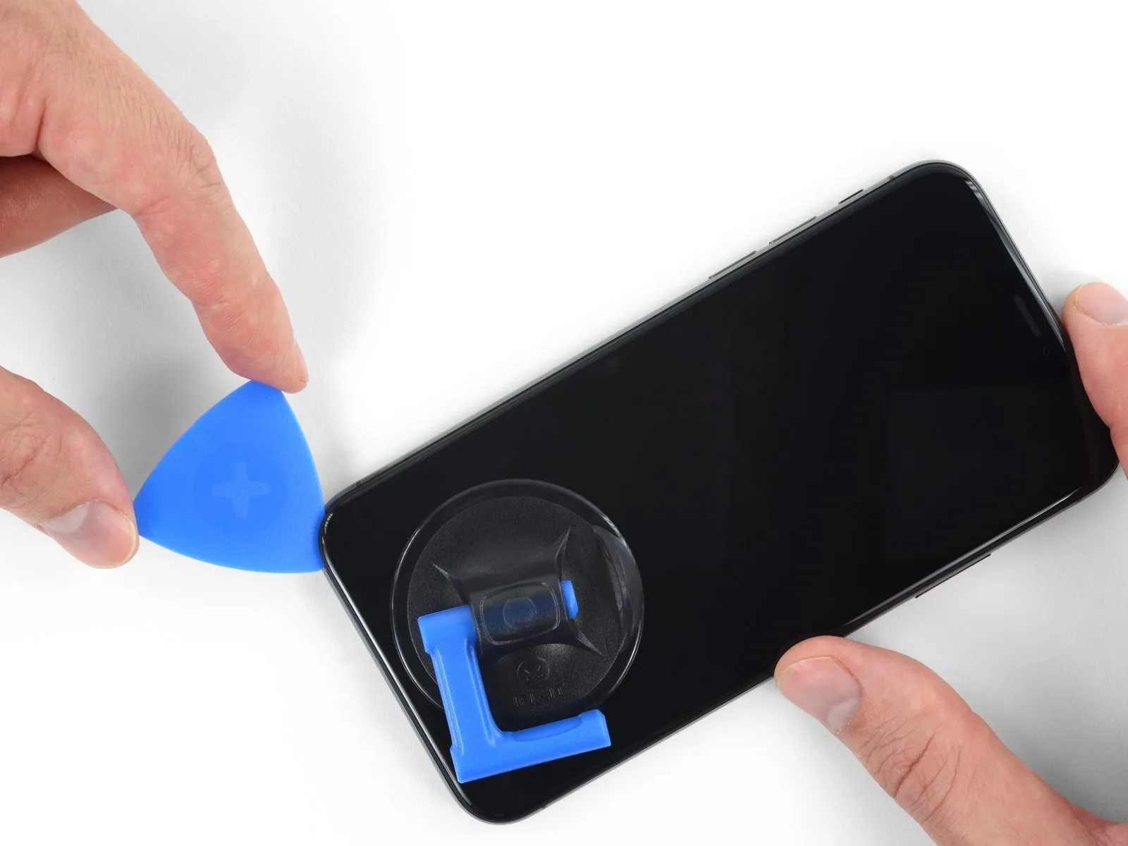
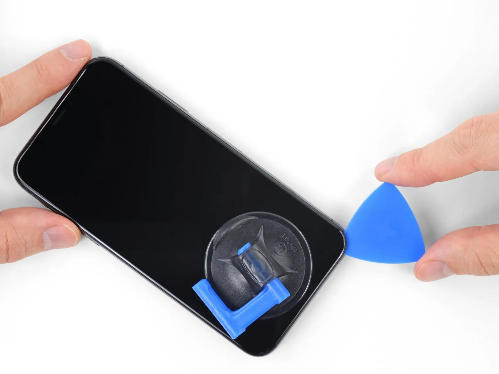
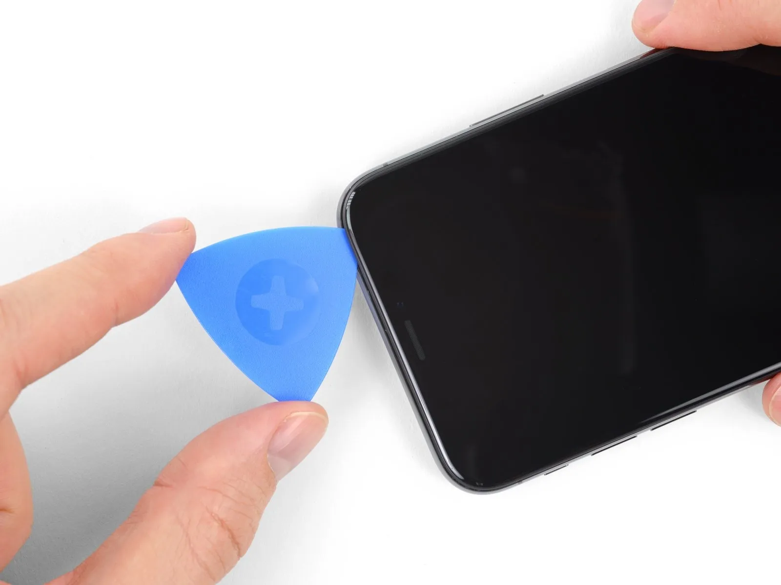
- Carefully maneuver the opening pick along the bottom-left periphery of the iPhone and upward along the left side, severing the adhesive securing the display assembly.
- Maintain a maximum insertion depth of 3 millimeters for the pick to prevent potential harm to the delicate internal components.
Step 13 | Screen information
- Fragile wiring is situated on the right-hand side of the iPhone; avoid inserting any tools in this area to prevent potential cable damage.
Step 14
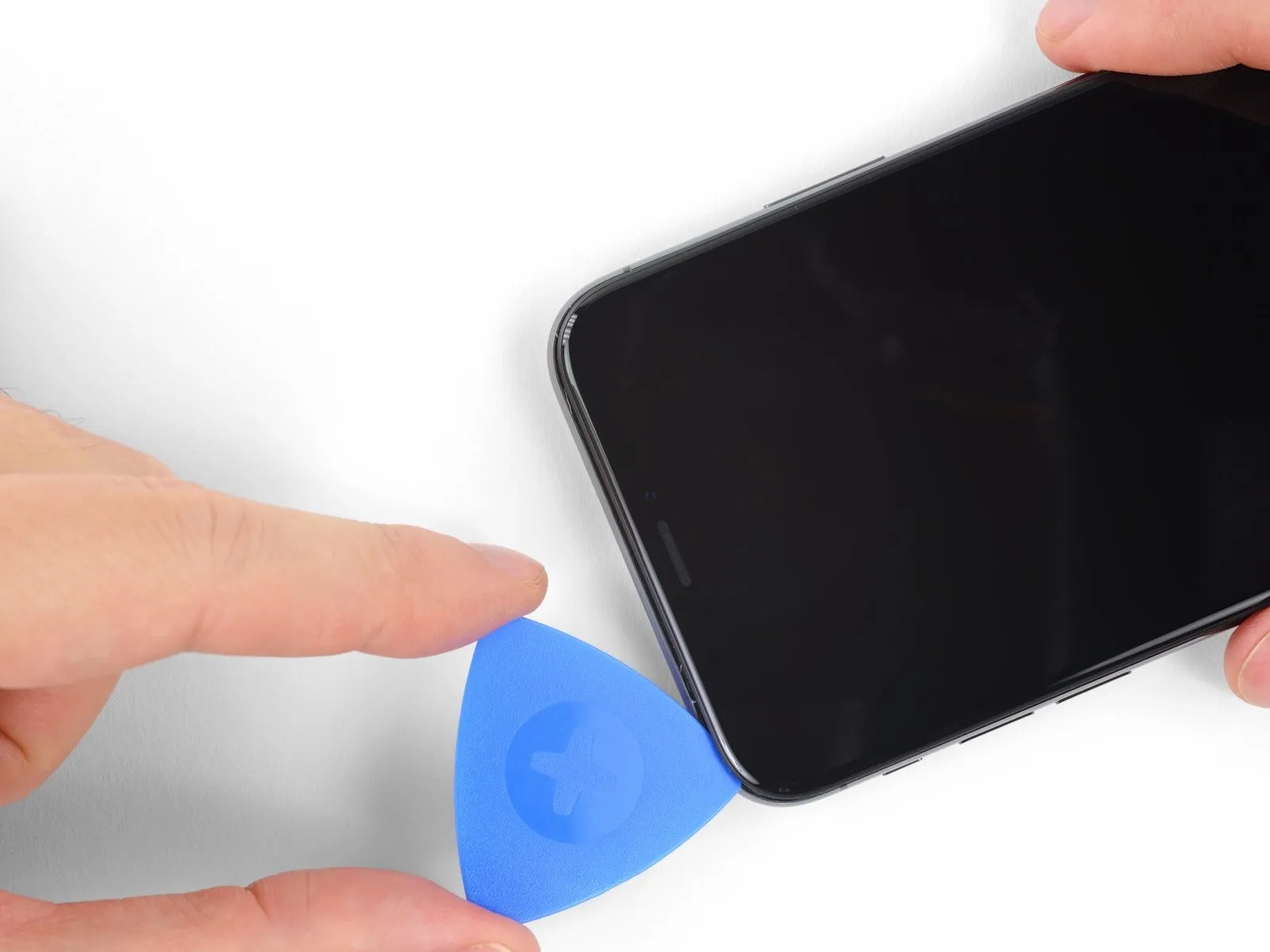
- To proceed with disengaging the adhesive, re-position your opening tool at the lower boundary of the iPhone's display and advance it upwards along the right-hand perimeter.
Exercise caution to limit the tool's insertion depth to a maximum of 3 millimeters, to prevent potential harm to the delicate display cable connections.
Step 15
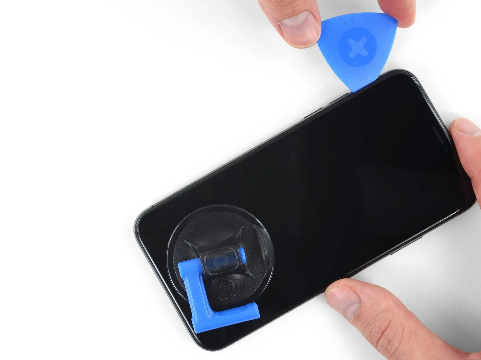
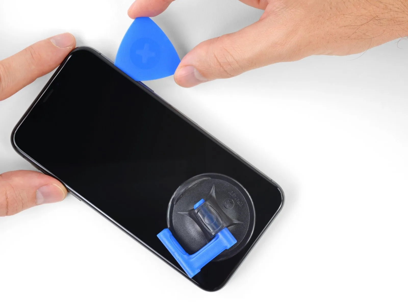
- Adhesive and retaining clips together fasten the uppermost border of the screen.
Employing a separation tool, maneuver it along the upper corner of the screen, applying slight downward pressure with gentle movements towards the Lightning connector.
Excessive force will cause the clips to fracture; therefore, proceed with caution and allow ample time. - Avoid inserting the tool beyond a depth of 3 millimeters to prevent potential harm to the front panel sensor array.
Continue the tool's movement to the opposing corner to sever any residual adhesive holding the screen in place.
Step 16
- Detach the suction cup from the front panel's surface by exerting traction on the small protrusion located on its body.
Step 17
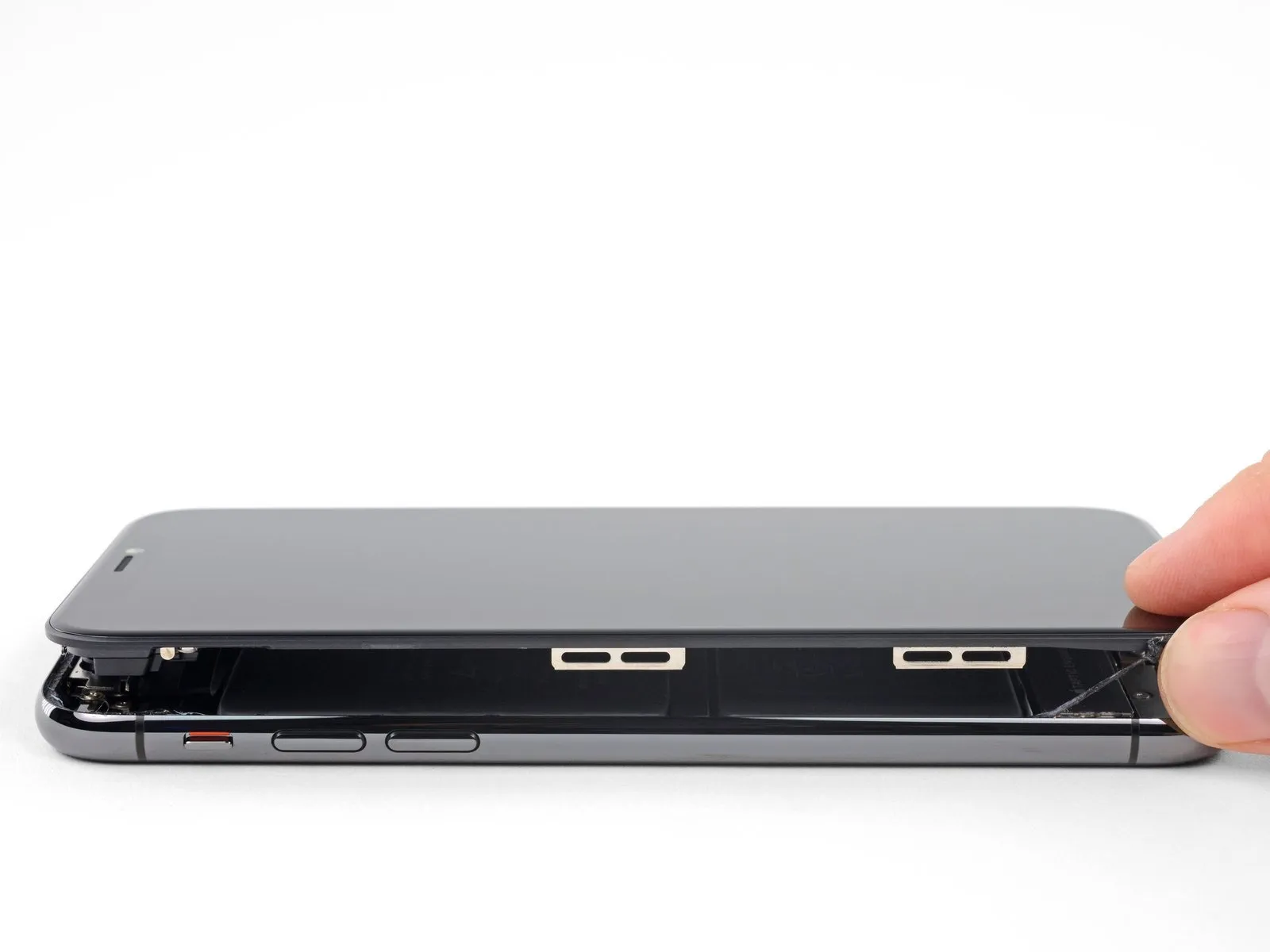
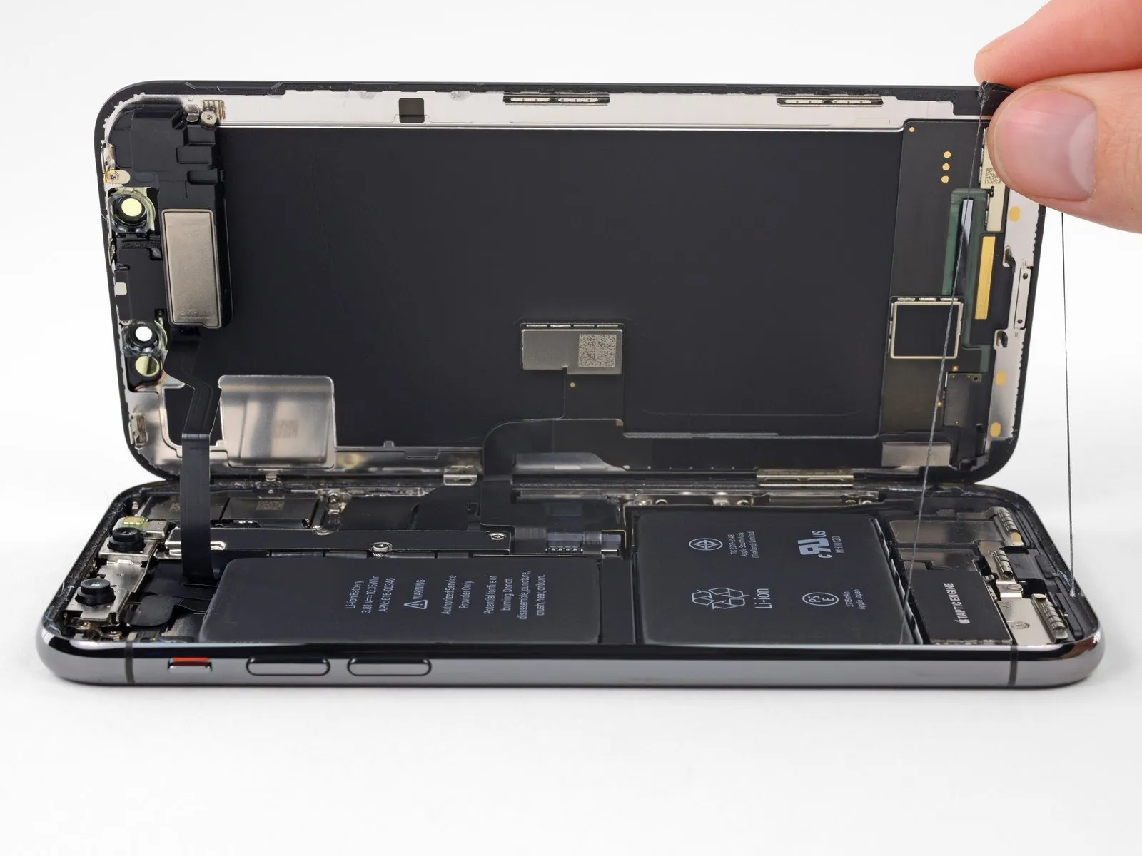
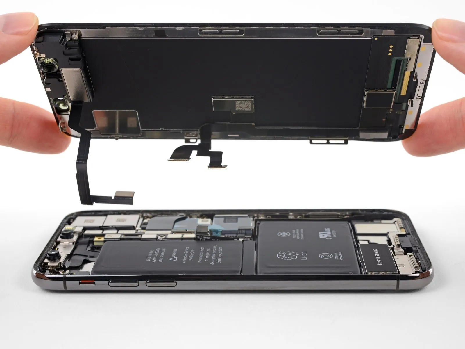
- To access the internal components, initiate the display opening process by pivoting the screen upwards from the left edge, mimicking the action of opening a book's cover.
- Refrain from completely detaching the display assembly at this stage, because multiple delicate ribbon cables remain connected to the iPhone's main circuit board.
- Confirm, as illustrated, that the frame lifts away from the device alongside the display, preventing it from becoming lodged inside.
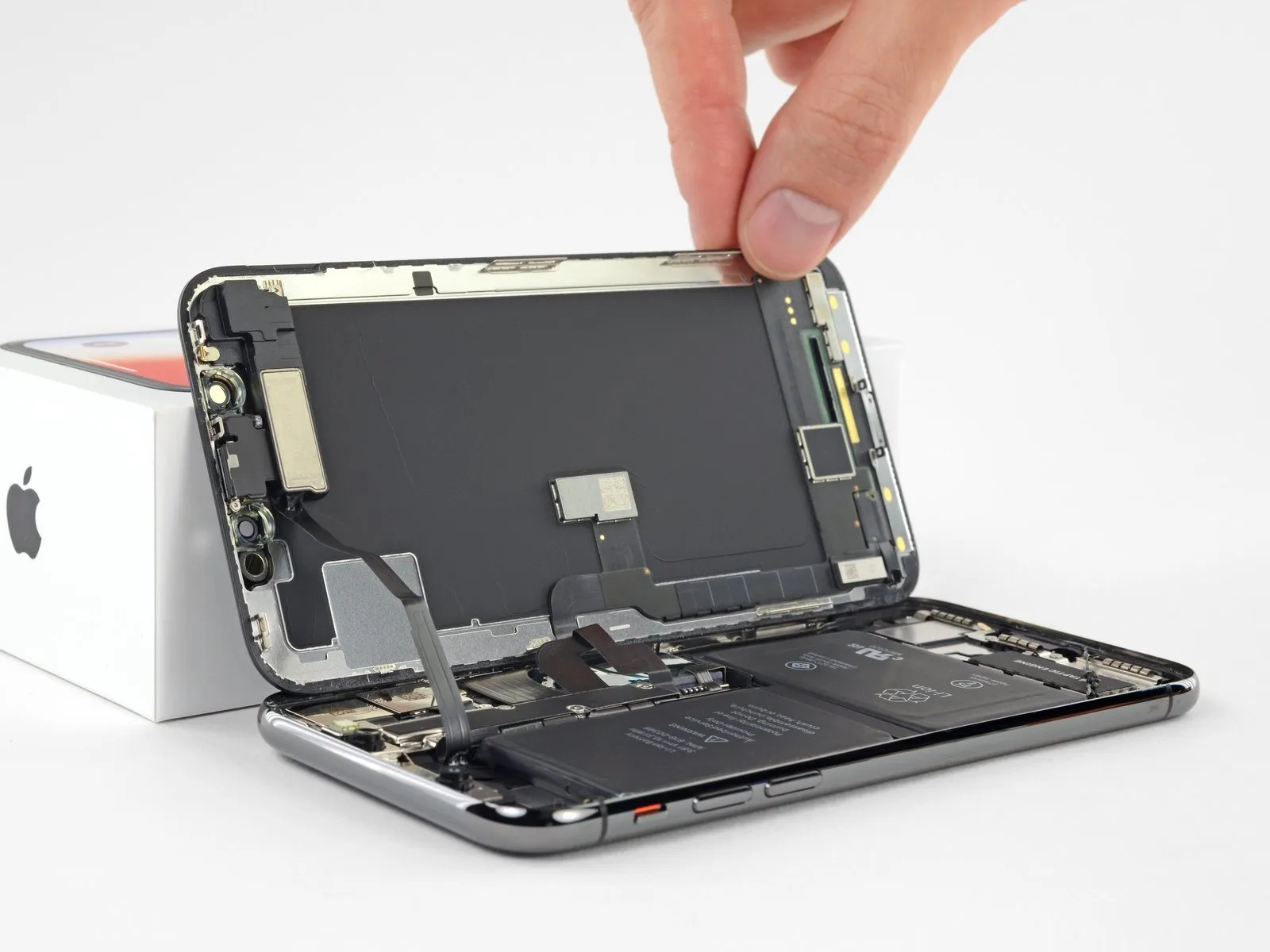
- Secure the display in an upright position using a support to maintain access to the internal components during the repair.
- When reassembling the device, position the display, ensuring the retaining clips along the upper edge are properly aligned, and then gently apply pressure to the top edge before securing the remainder of the display. If resistance is encountered during closure, inspect the condition of the clips surrounding the display's perimeter to verify they are free from deformation.
Step 18 | Display Assembly
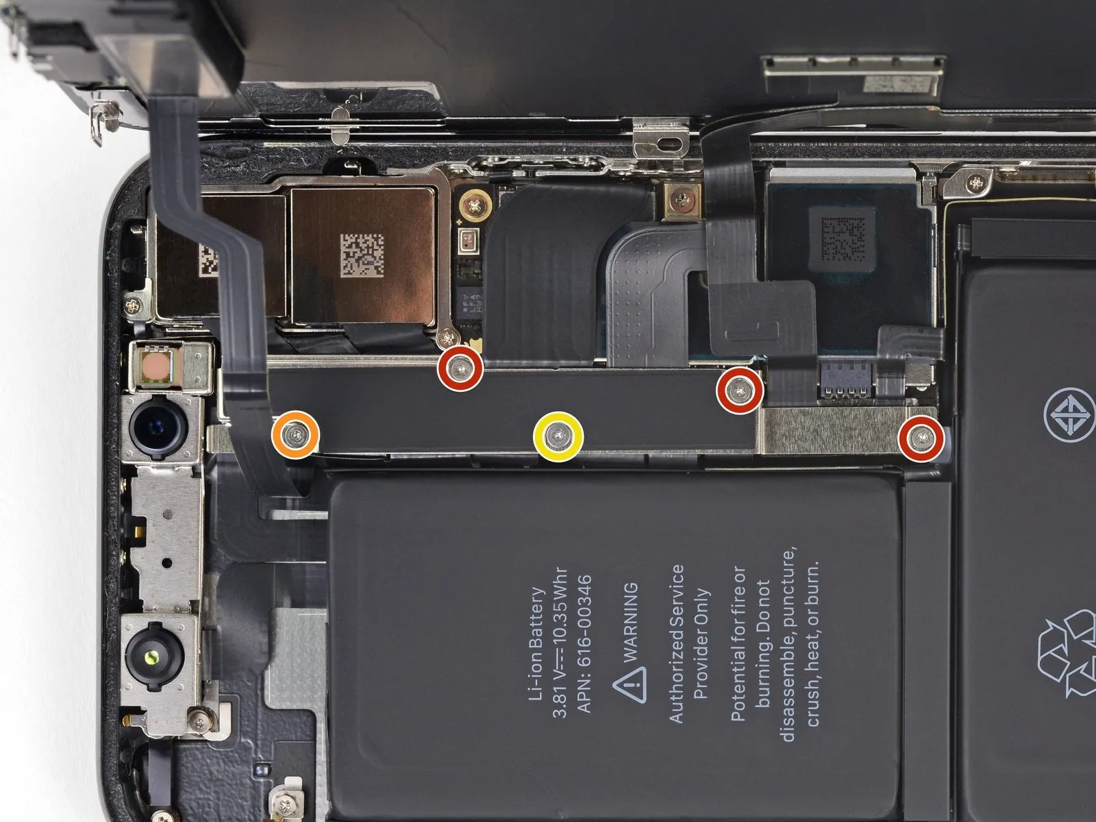
- To detach the logic board connector bracket, initially extract the five Y000 screws that hold it in place, noting the varying lengths of each fastener.
Specifically, three screws measure 1.1 millimeters in length.
A single screw is 3.1 millimeters long.
Additionally, one screw has a length of 3.7 millimeters.
During the entire repair process, meticulously organize and document the location of each screw, ensuring their correct reinstallation to prevent potential damage to the iPhone.
Step 19
- Detach the bracket from the device.
The bracket could be subtly affixed; apply a careful, yet resolute upward force to disengage it.
As you put the iPhone back together, it's advisable to activate the device and verify every feature's operation prior to securing the display. Ensure the iPhone is fully powered off before proceeding with the repair.
Step 20
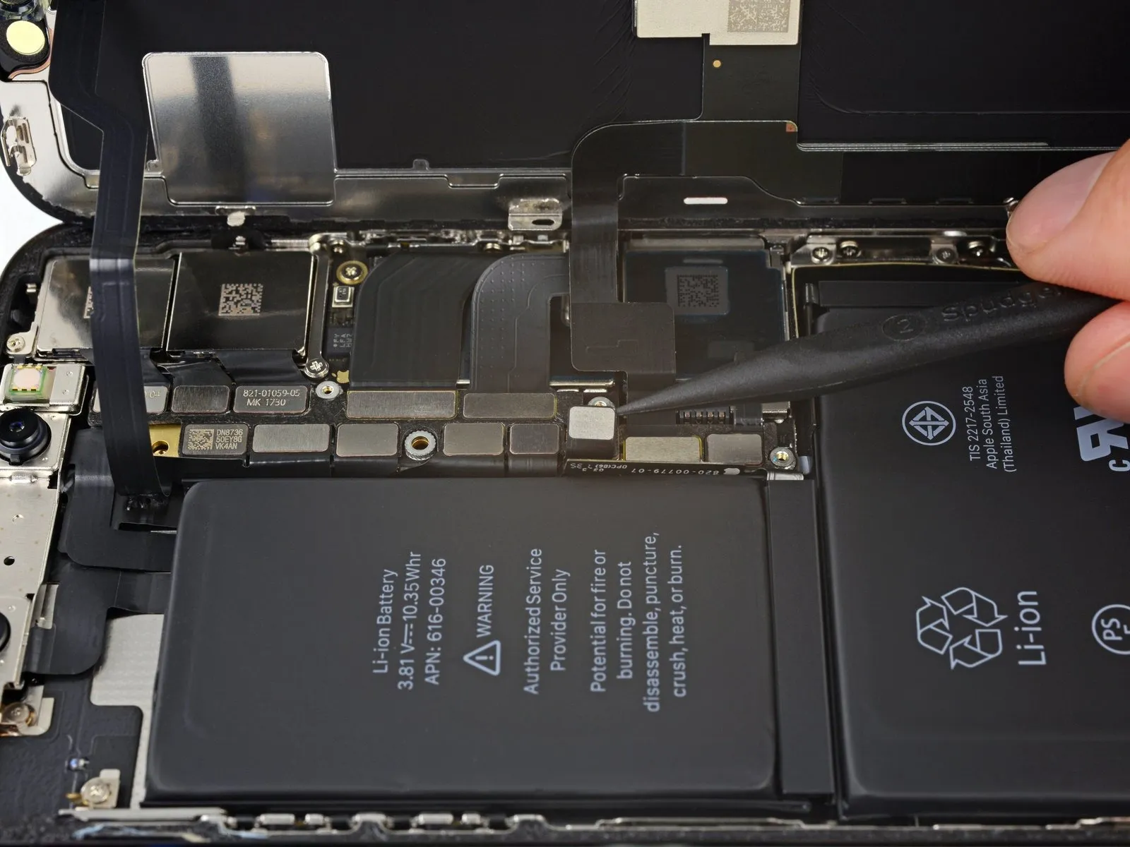
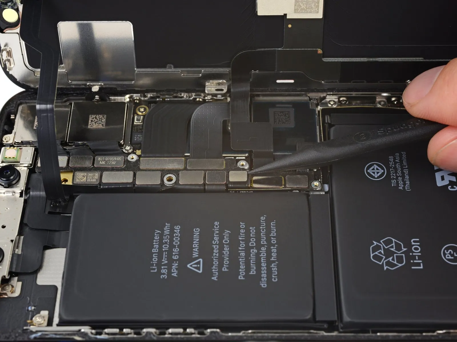
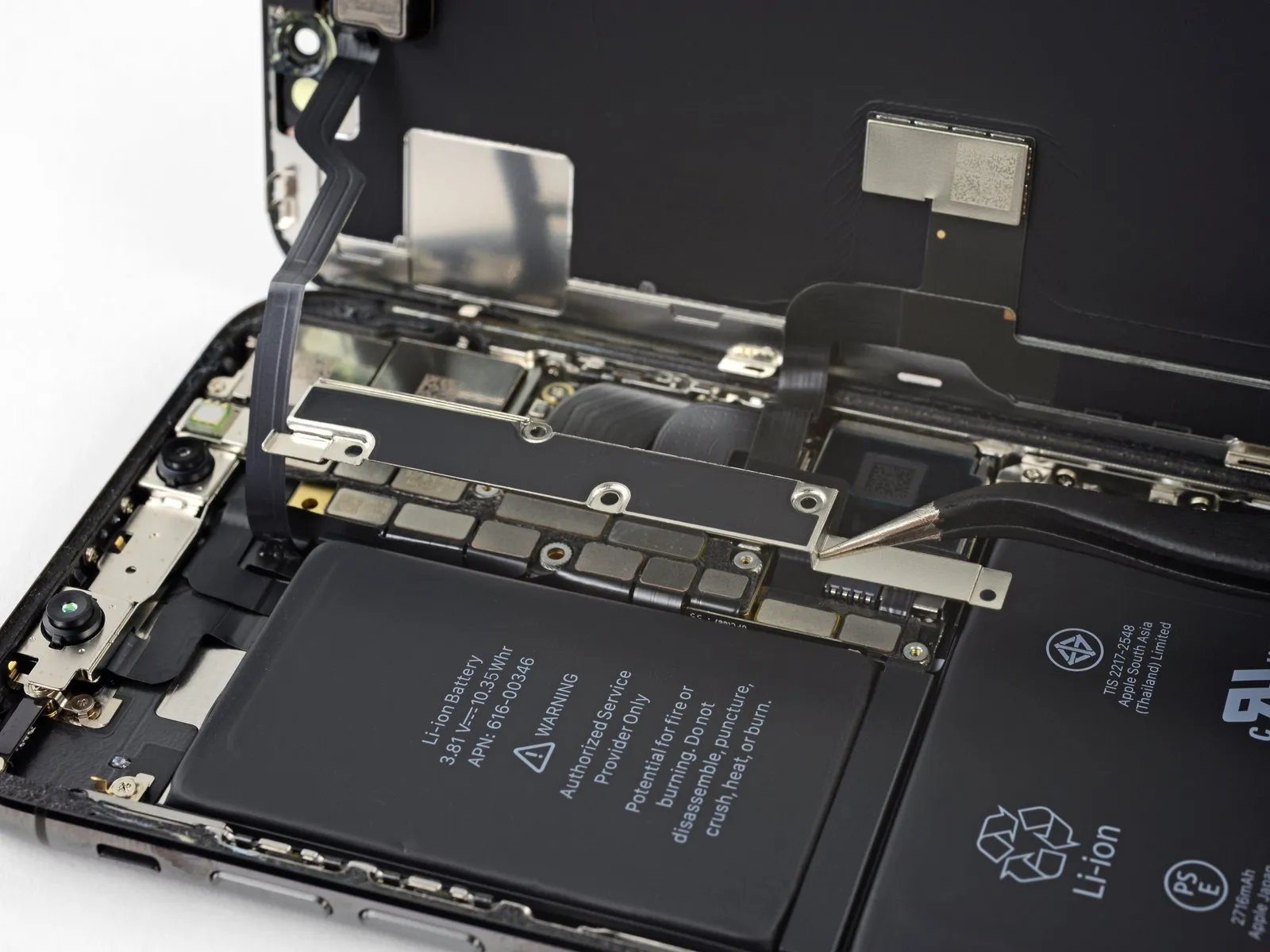
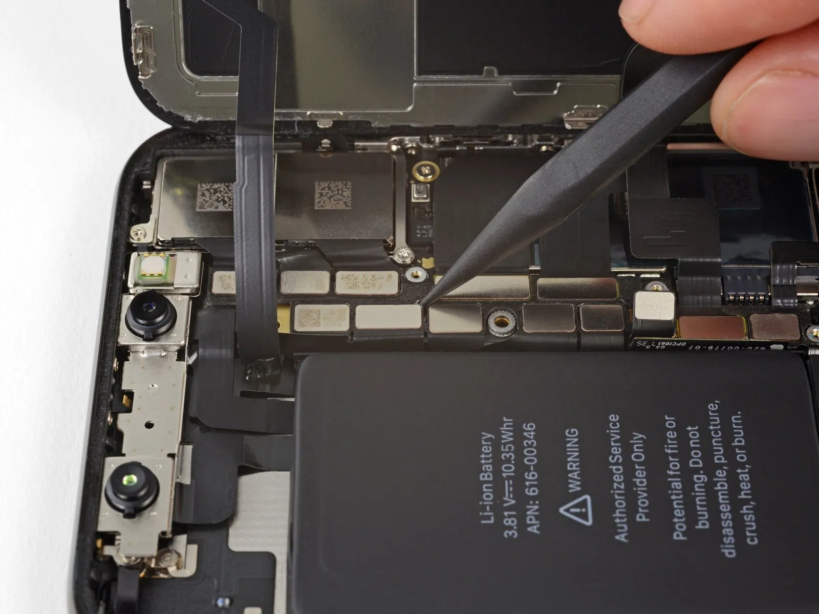
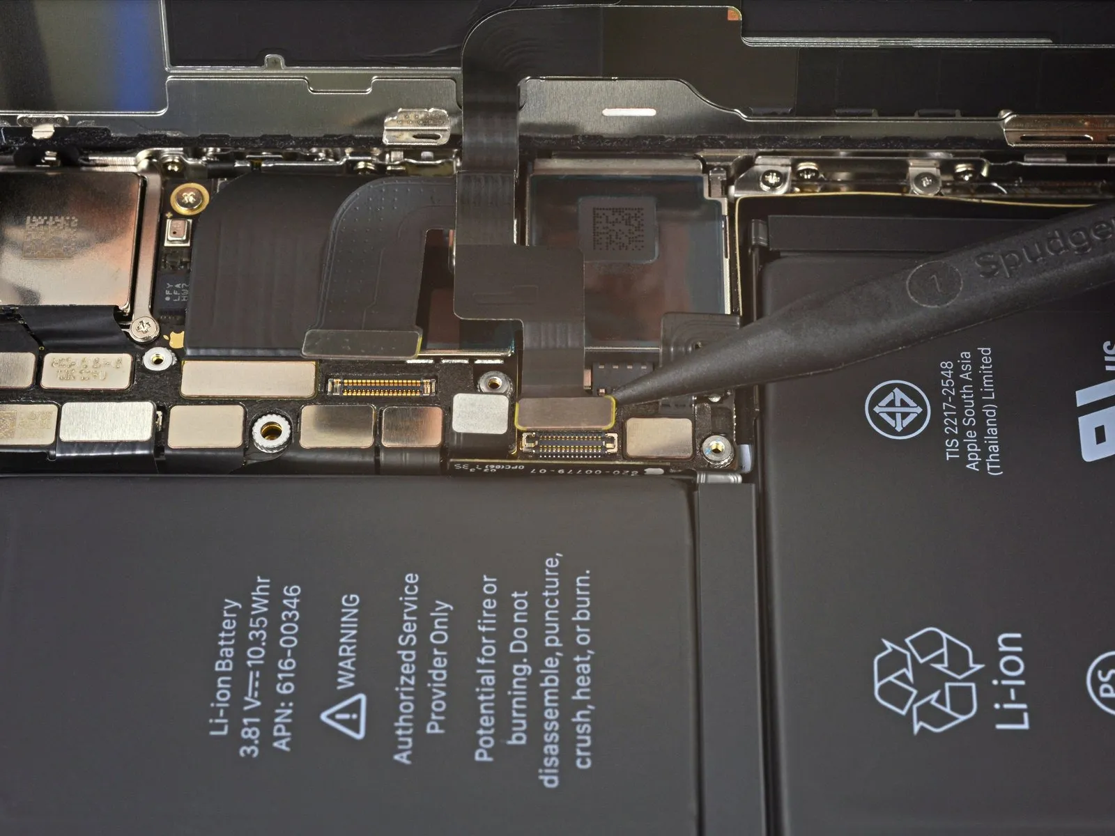
- Employing the tip of a spudger or a pristine fingernail, carefully lift the battery connector away from its corresponding receptacle on the logic board.
Exercise caution to avoid harming the black silicone seals that encircle this connector and others on the board, as they offer supplemental defense against water and dust penetration.
Slightly deflect the connector outward from the logic board to ensure it remains disconnected and prevents unintended power delivery to the device during the repair process.
Step 21
Step 22
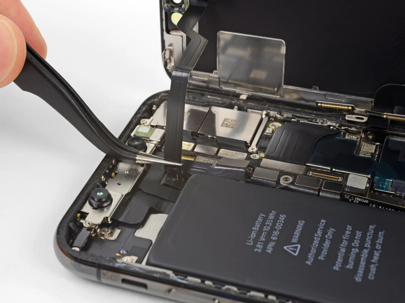
- Employ the tip of a spudgeror a fingernailfor separating the OLED panel cable connector.
- To secure the connection, apply pressure in this manner: initially, ensure proper alignment and depress one edge until a distinct click is heard, subsequently repeating the process on the opposing edge. Avoid applying pressure to the central portion of the connector; misalignment can result in pin deformation and irreversible damage.
Step 23
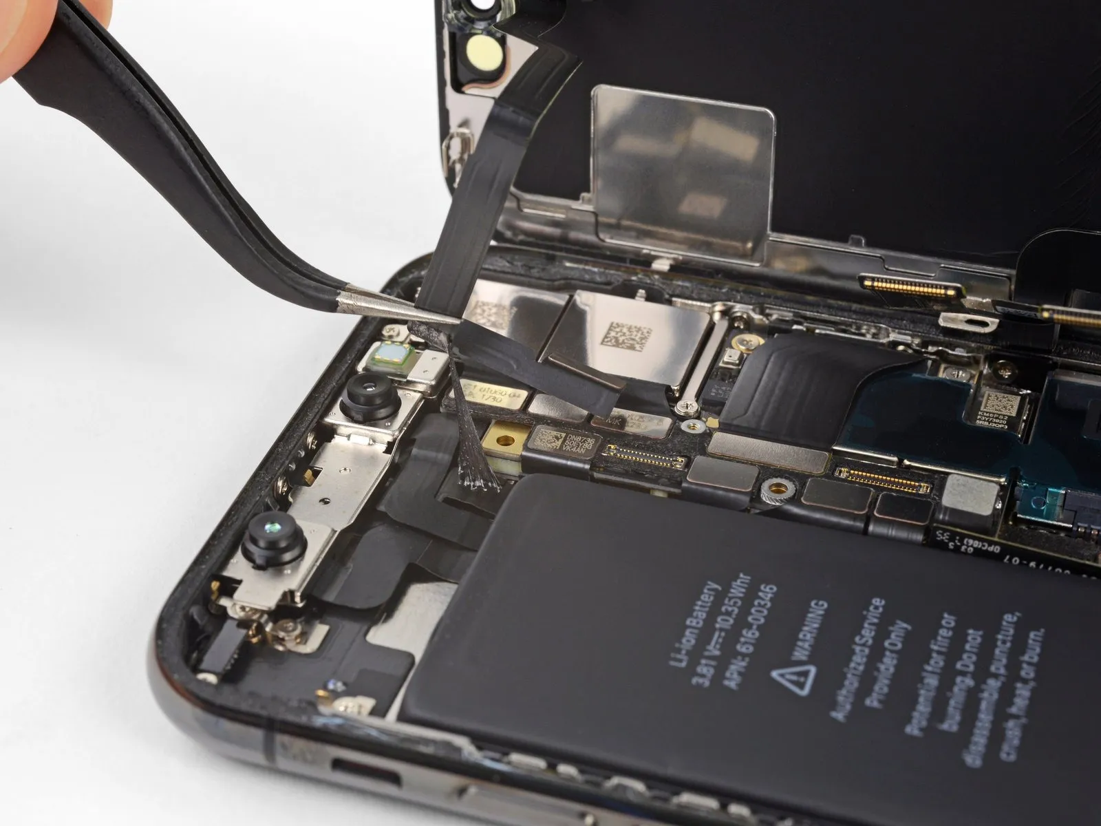
- Employ the tip of a spudgerto carefully lift the digitizer cable connector from its receptacle.
- Due to the connector's deeply set position, reattachment can be challenging; proceed deliberately, ensuring precise alignment before applying gentle pressure with your fingertip to secure it – initially one side, then the other, observing an audible click confirming its proper engagement.
- Should any area of the screen exhibit unresponsive touch functionality following the repair, first remove the battery, then re-engage this connector, verifying a full click and confirming the absence of dust or any other impediment within the socket.
Step 24
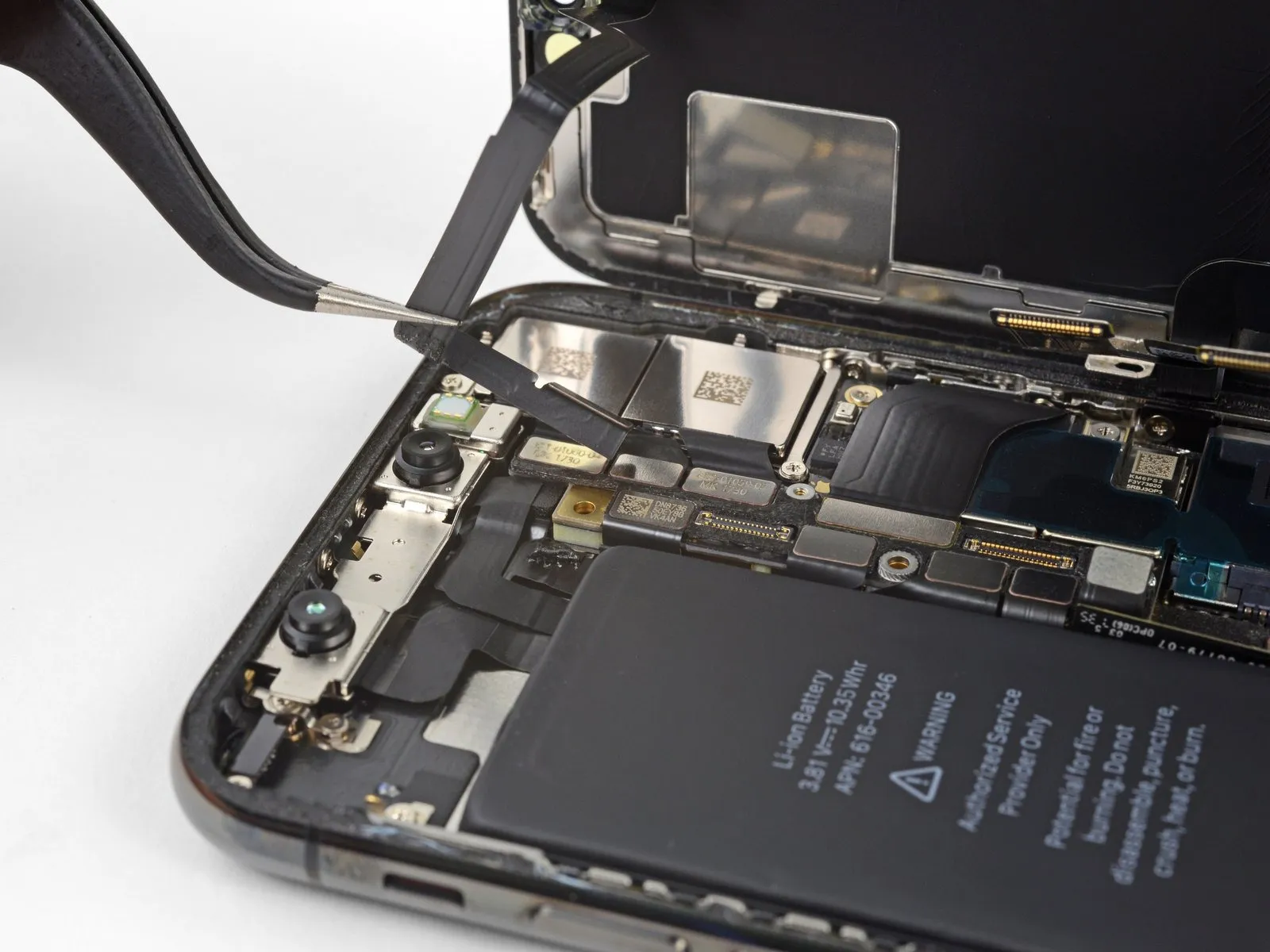
The assembly containing the front panel sensor is secured with a delicate adhesive along its flex cable.
Gently raise the cable to detach it from its position, ensuring the adhesive bond releases without damage.
Step 25
- Detach the display unit from the device.
- When putting the device back together, halt at this point should you desire to substitute the water-resistant adhesive that seals the display's perimeter.
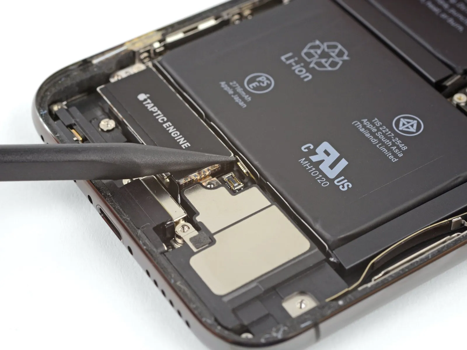
Step 26 | Lower Speaker
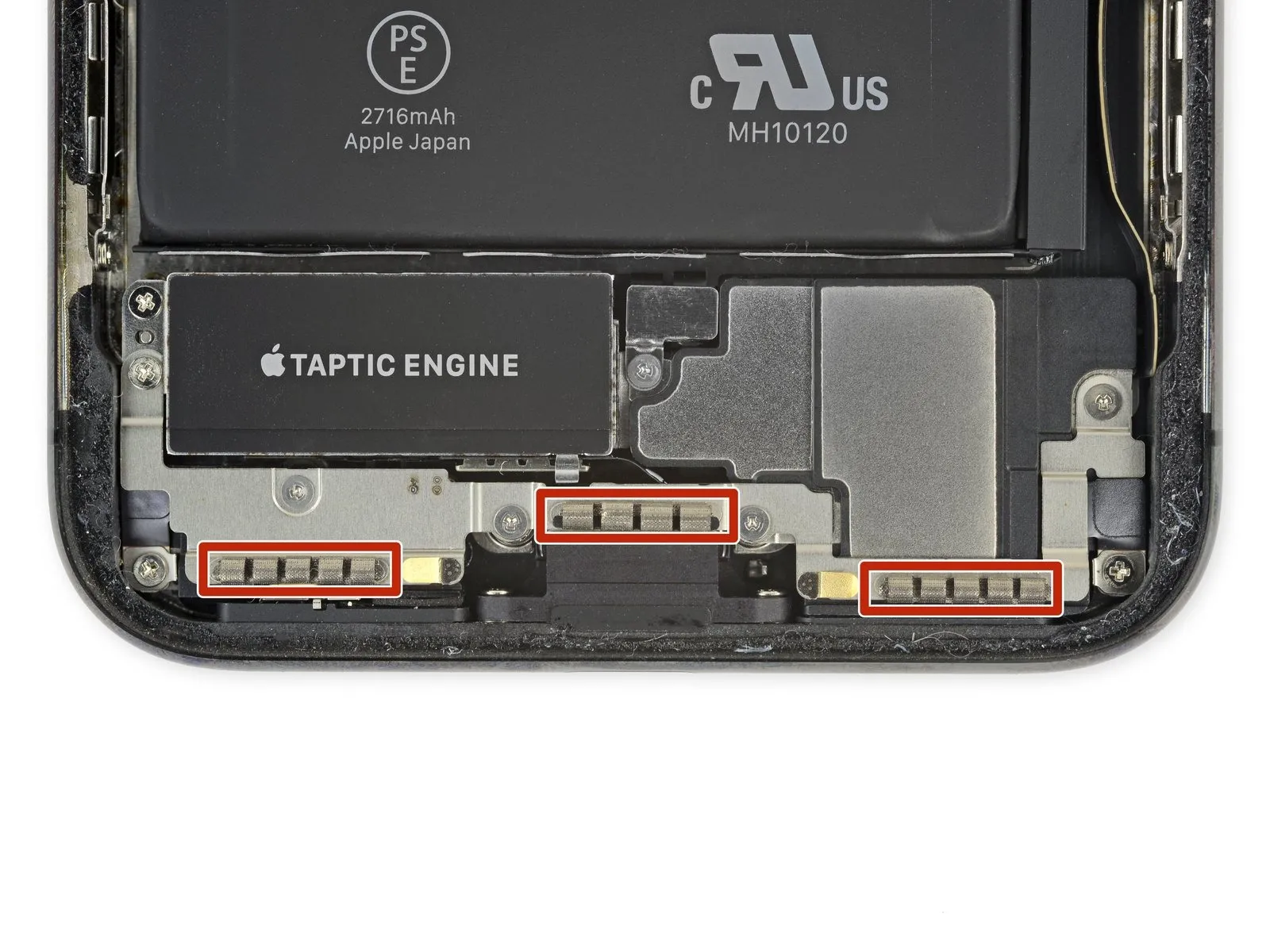
- Exercise caution to avoid contact with the three rows of grounding pads located close to the base of the iPhone.
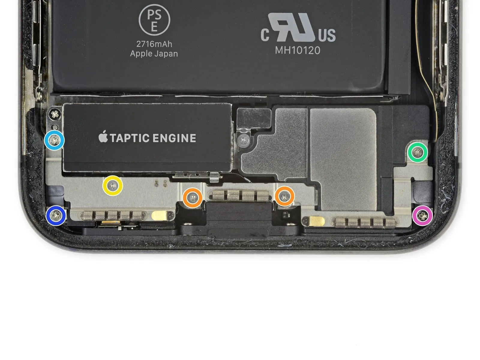
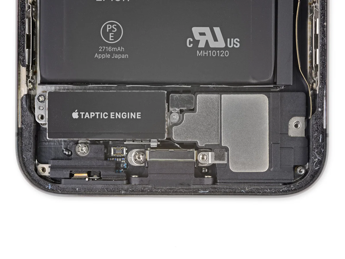
- Detach the bracket situated beneath the Taptic Engine and speaker by unscrewing the seven fasteners it holds.
- Two screws of type Y000, each measuring 1.9 mm in length, are required.
- A single Y000 screw with a length of 1.2 mm must be removed.
- A single Y000 screw, measuring 1.6 mm in length, is also needed.
- A Phillips-head screw, measuring 2.4 mm across, is necessary for disassembly.
- A Phillips-head screw with a 1.7 mm diameter is also part of the assembly.
- A Phillips-head screw, measuring 1.5 mm in diameter, completes the fastener set.
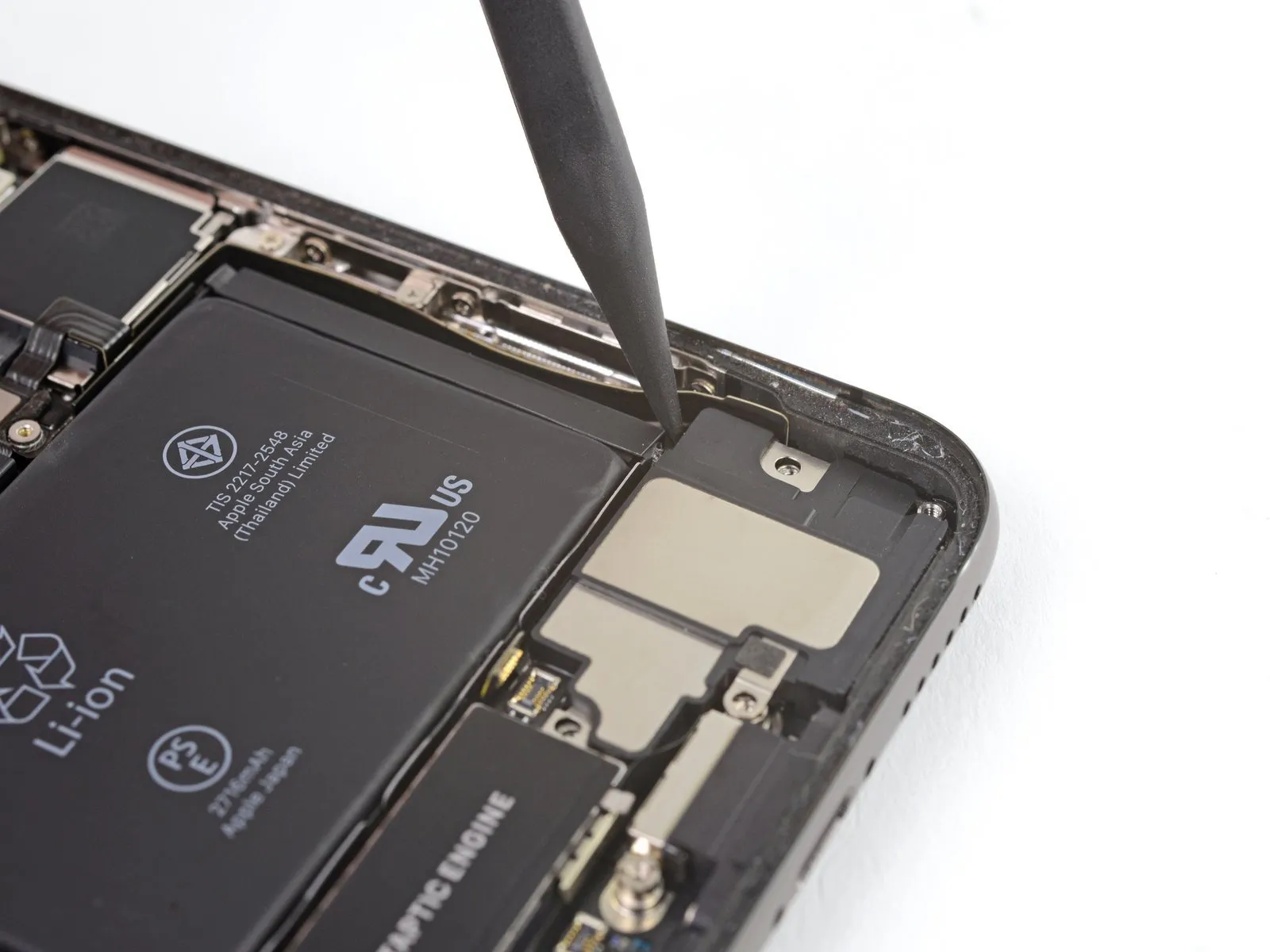
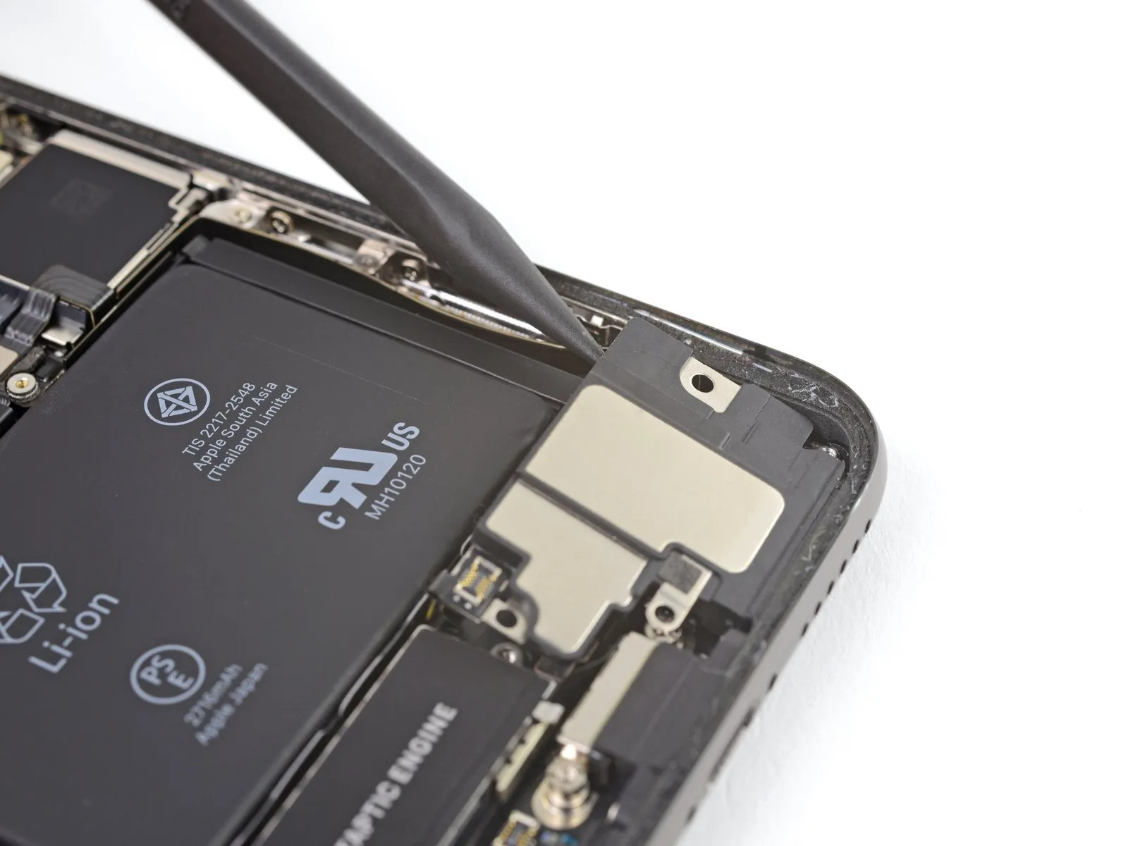
Step 27
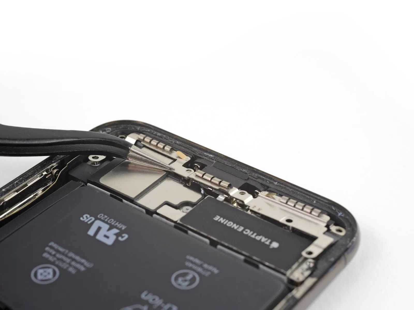
- To detach the bracket, elevate it starting from the side closest to the battery.
- Avoid complete removal at this stage, because a short, flexible cable maintains its connection.
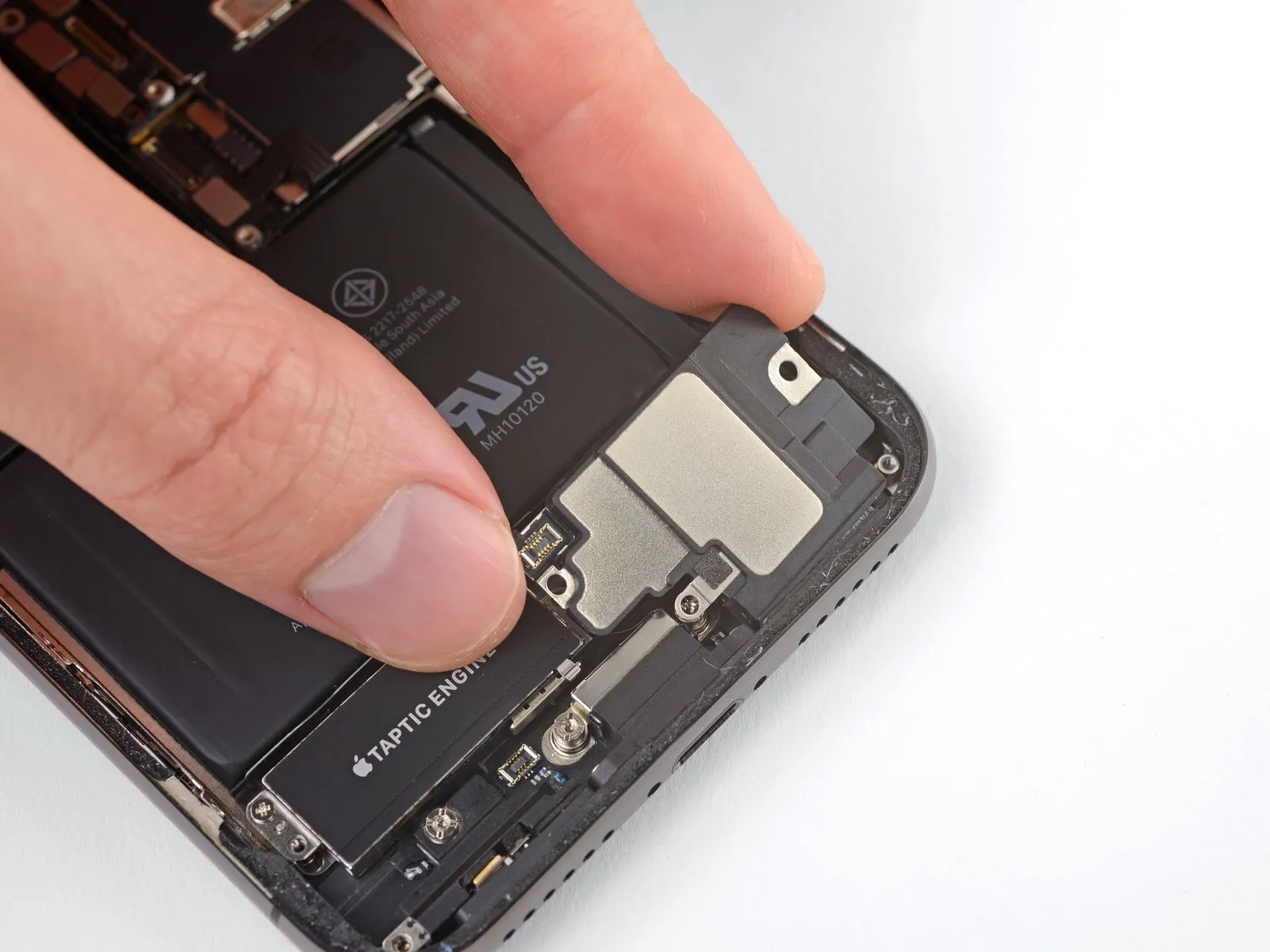
Step 28
- To prevent interference from the bracket, secure it aside, then utilize the tip of a spudger to carefully lift and detach the flex cable located beneath.
Step 29
Step 30
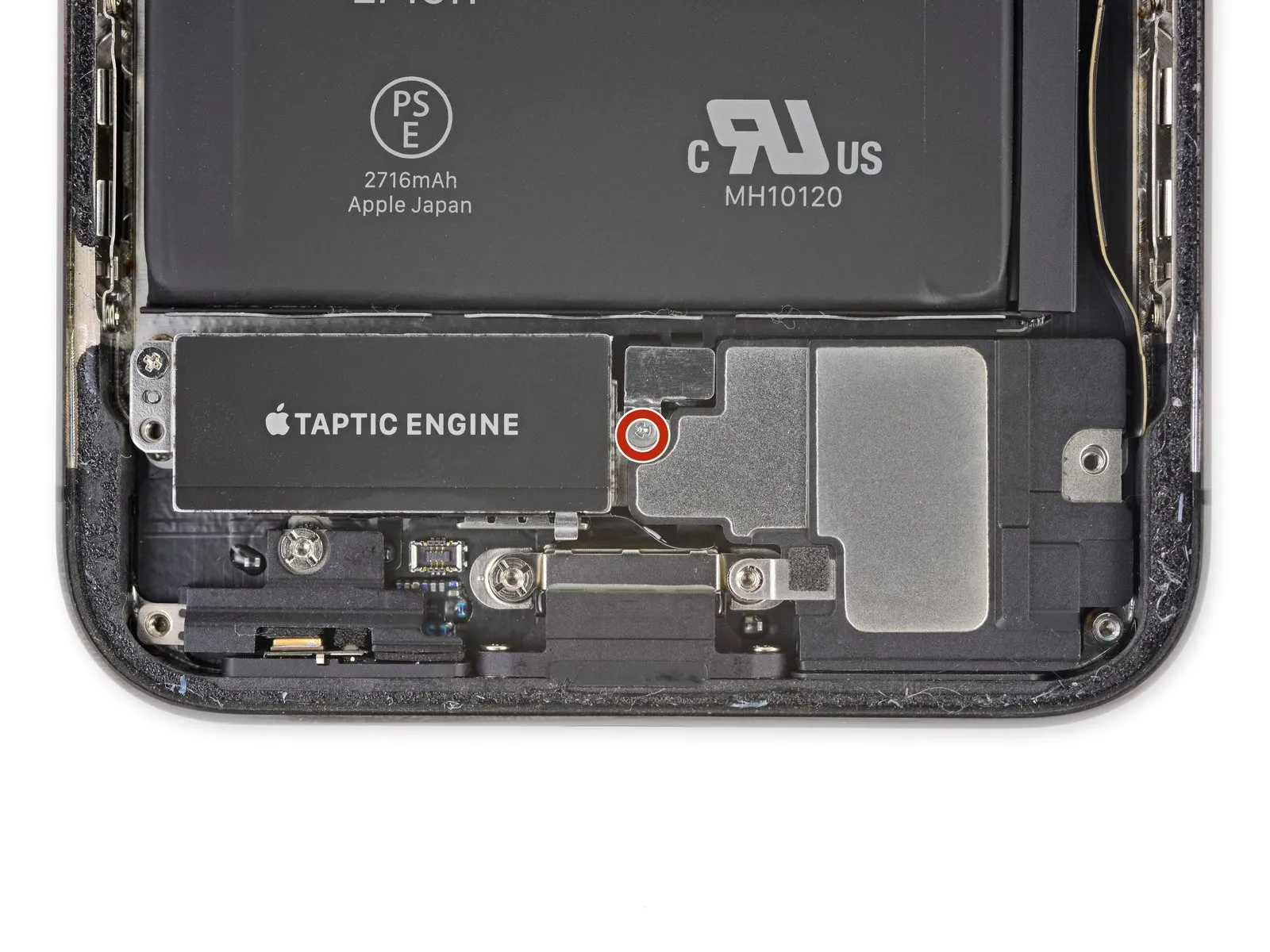
- Detach the2.1-millimeter Y000 screwwhich fastens the speaker connector cover in place.
Step 31
Step 32
- Employ the pointed end of a spudgerto carefully lift and detach the speaker's electrical connector.
Step 33
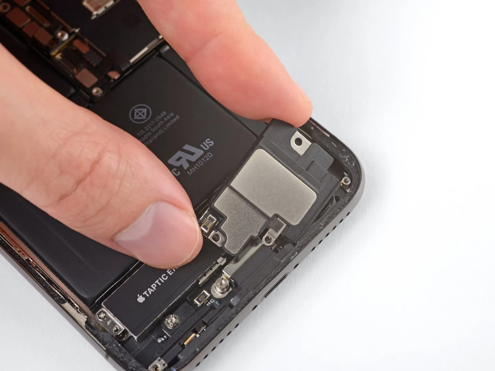
Exercise caution while separating the speaker from the device, preventing harm to the flex cable that was recently detached; if needed, secure the cable to the side to facilitate speaker removal.
- Position a spudger beneath the upper boundary of the speaker, situated close to the iPhone's casing.
- Apply slight upward pressure and elevate the speaker's upper edge with care.
During speaker reinstallation, verify the flex cable's alignment and confirm it remains free from entrapment beneath the speaker.
Step 34
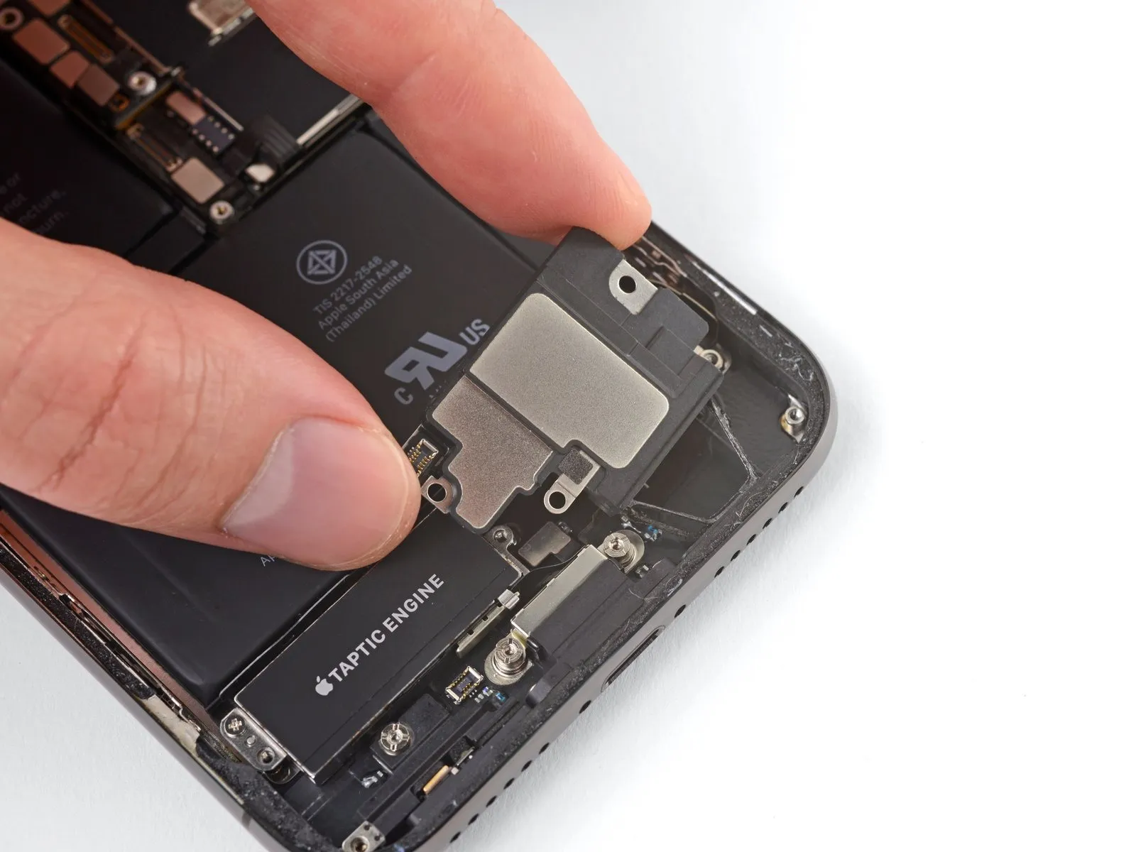
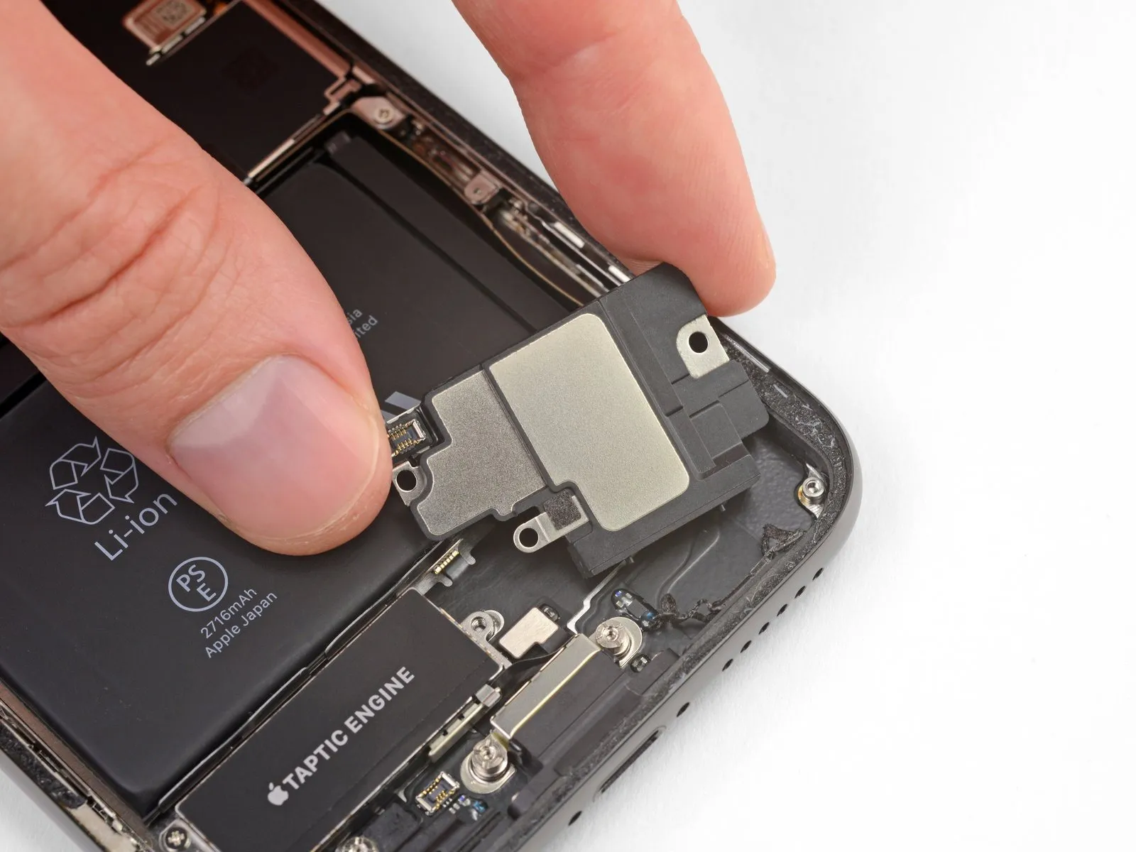
Grasp the speaker assembly using its lateral edges, gently oscillating it to disengage the adhesive that bonds it to the iPhone's lower perimeter.
- Continue moving the speaker outward from the iPhone's base until the adhesive gasket, which provides a seal, fully detaches.
Step 35
Detach the speaker component from the device.
Step 36 | Replace the speaker gasket
The speaker's gasket is designed for single use and cannot be reused; adhere to the following procedure when reassembling to ensure proper replacement.
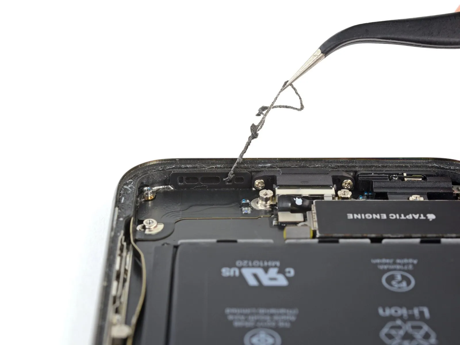
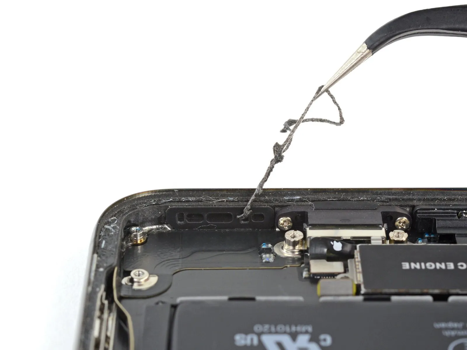
- Employ tweezers to carefully detach and eliminate all remnants of the previous gasket material from both the frame and the speaker itself.
- Thoroughly cleanse any adhesive residue left by the old gasket from the frame and speaker surfaces utilizing a microfiber cloth dampened with isopropyl alcohol.
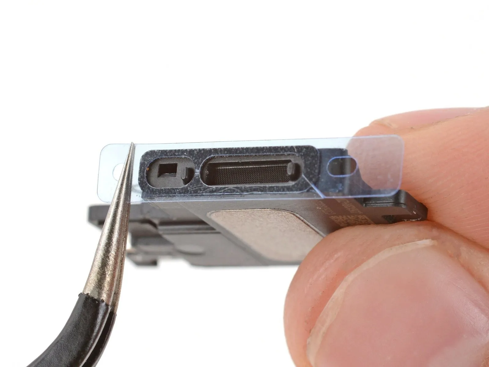
- Prior to installing the replacement gasket, identify its correct positioning on the speaker's underside, noting that the substantial recess should align with the speaker grille's mesh pattern.
- Detach the larger, transparent protective layer from the gasket and, using tweezers, precisely position the gasket onto the speaker's underside.
- To prevent contamination of the adhesive surface, restrict handling of the gasket to only the outer perimeter of its protective liner.
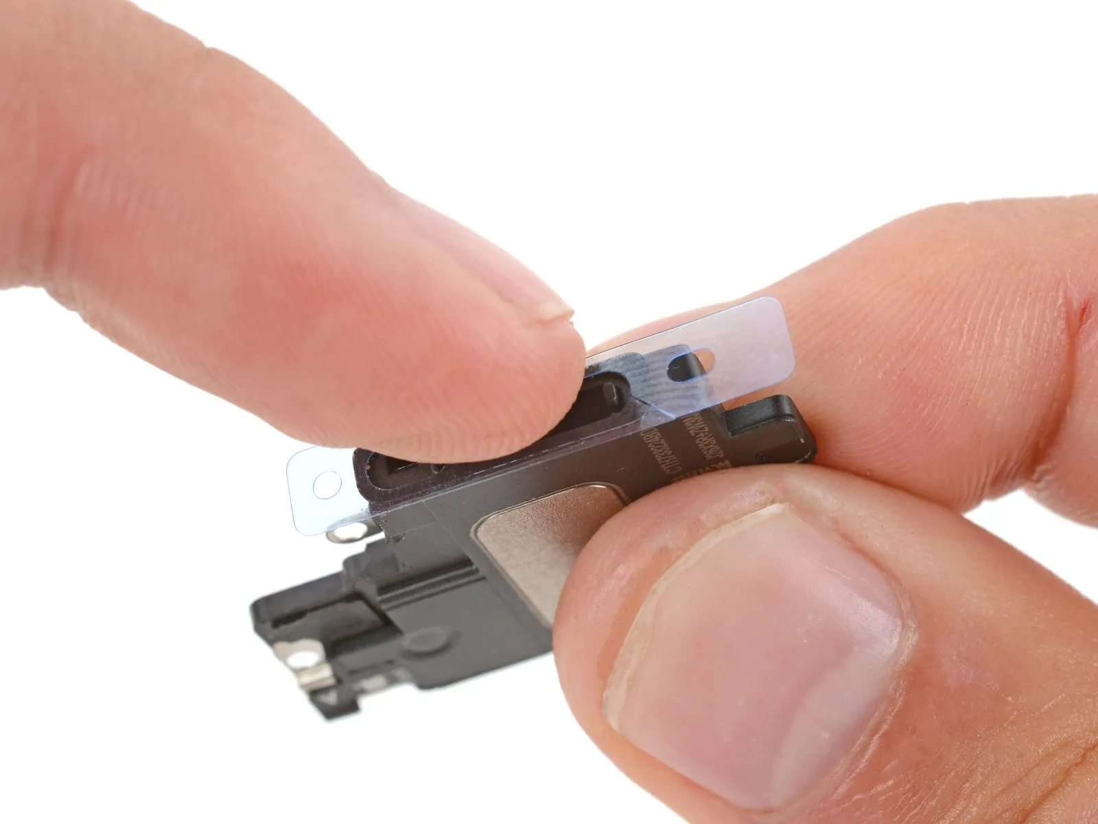
- Apply firm pressure with your fingers or a spudger to ensure the gasket adheres securely to the speaker via its adhesive backing.
- Remove the remaining liner and carefully install the speaker, verifying that the speaker connector remains free from obstruction and does not become trapped.
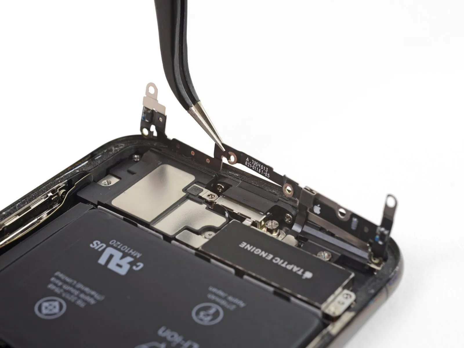
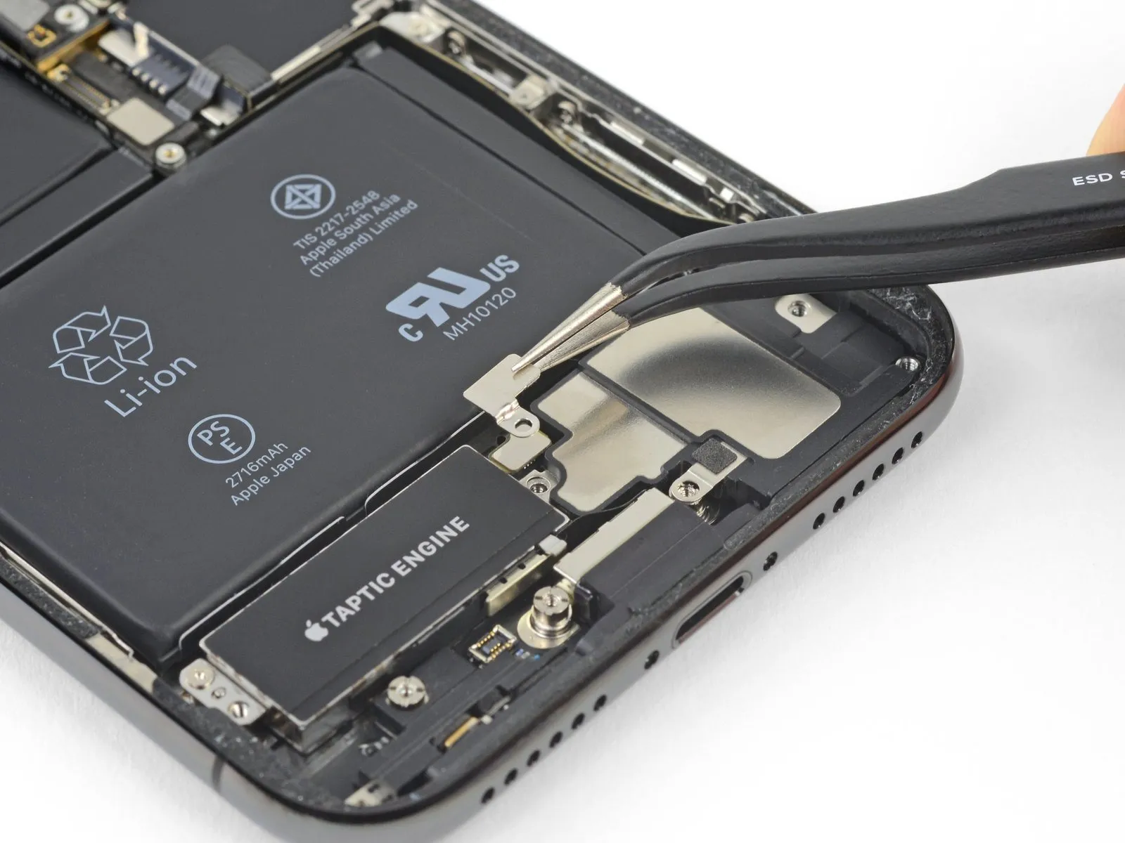
Step 37 | Taptic Engine

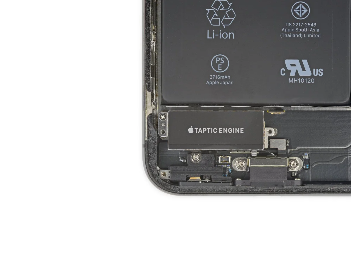
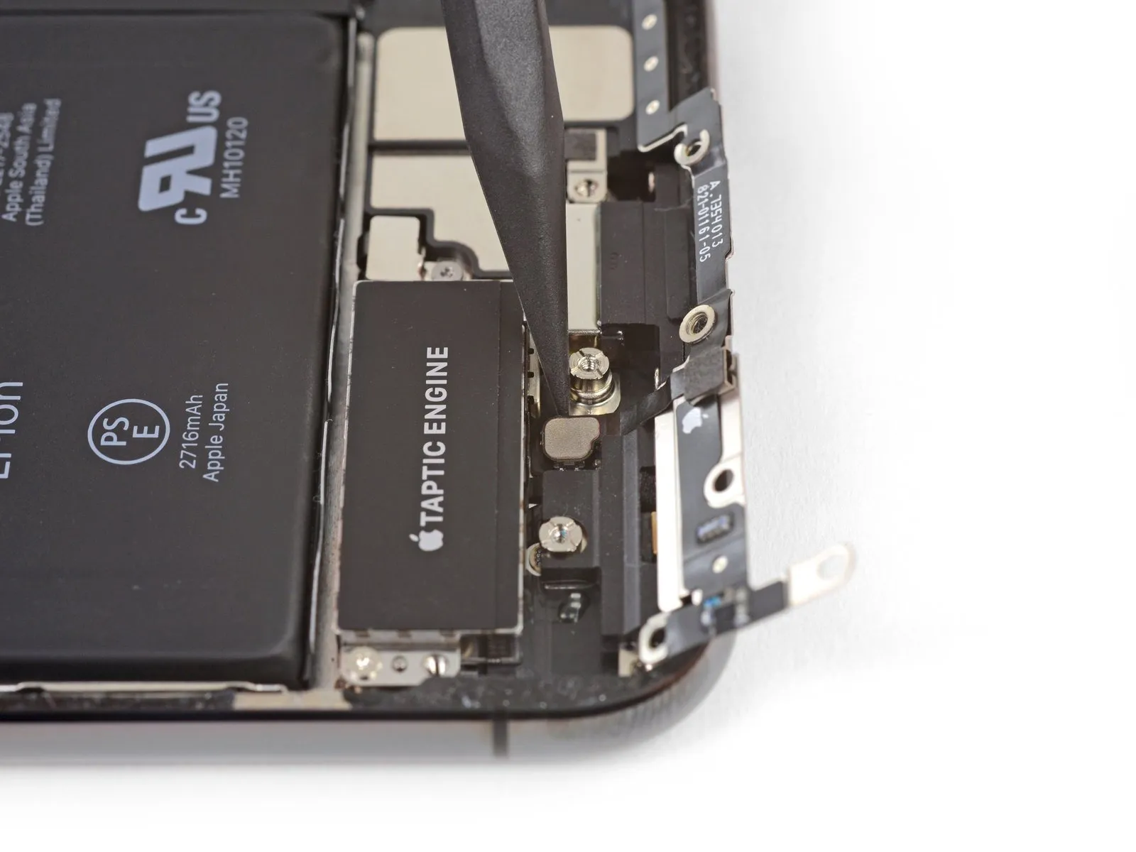
- To detach the component, eliminate the 2.3-millimeter Phillips screwwhich holds the Taptic Engine in place.
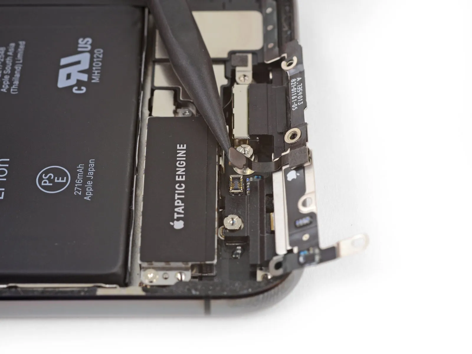
Step 38
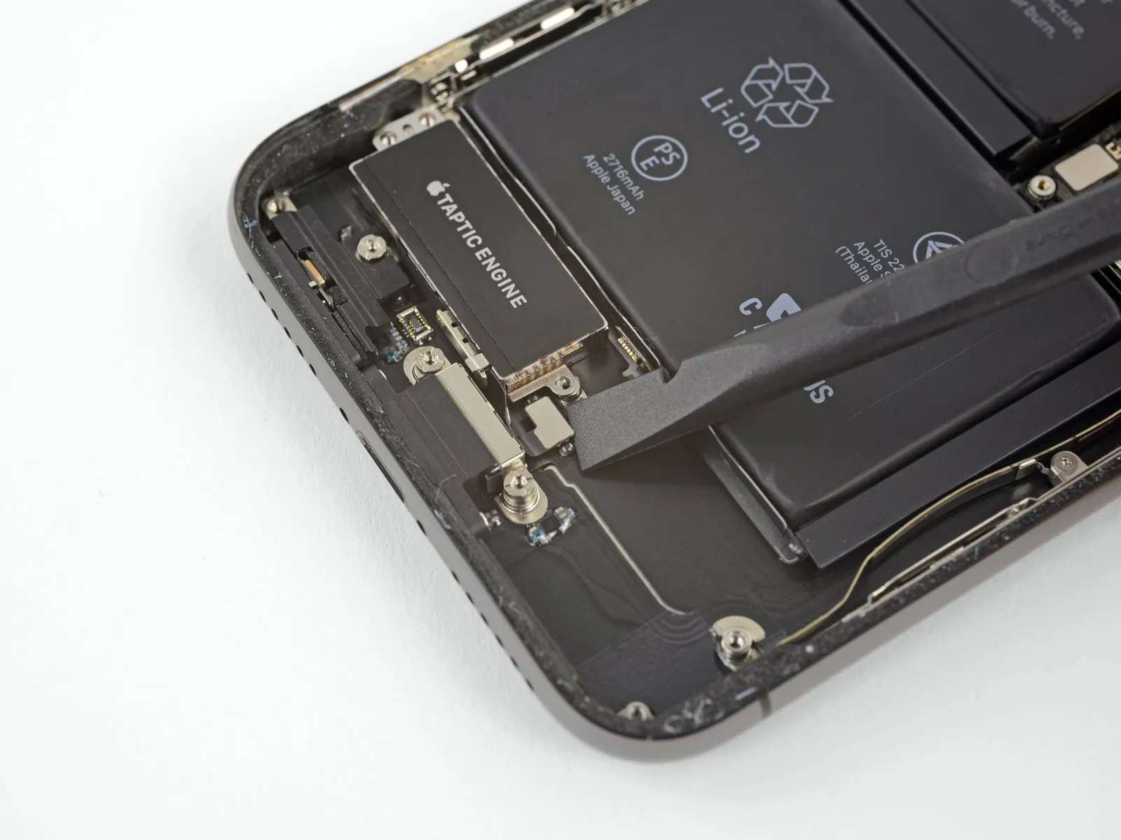
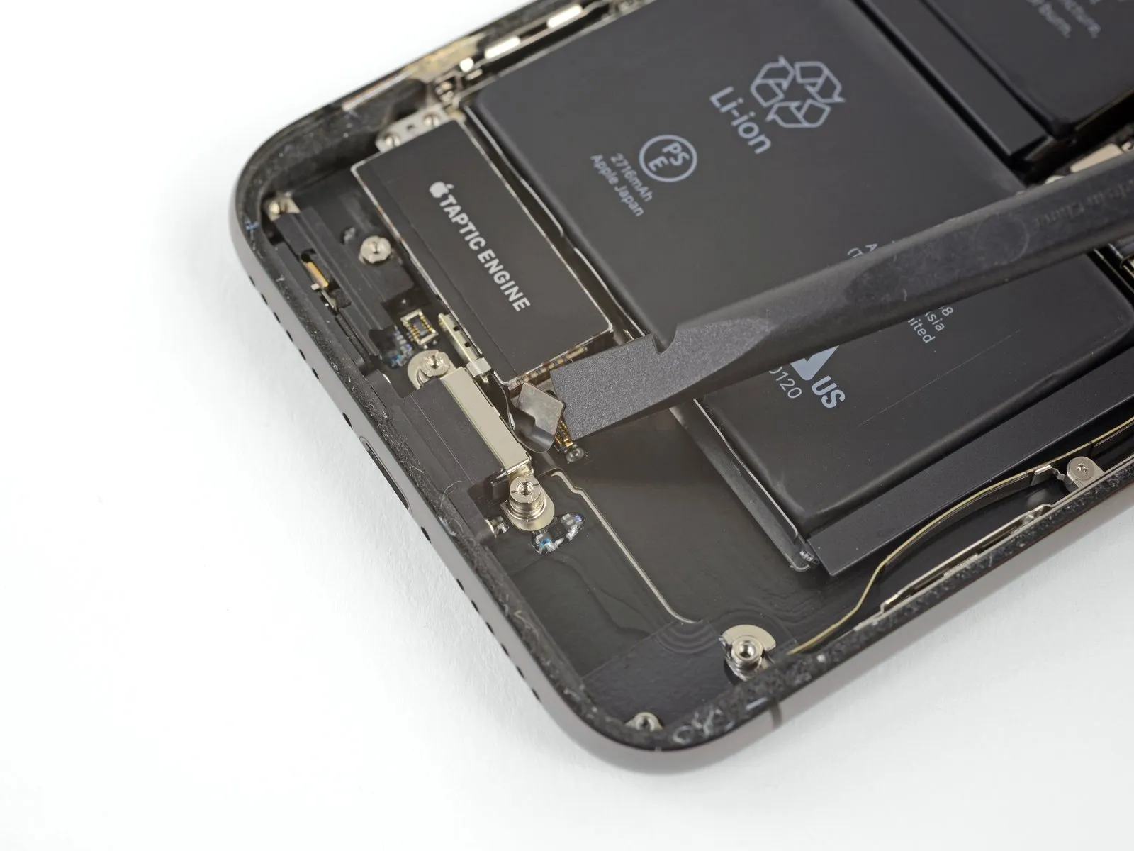
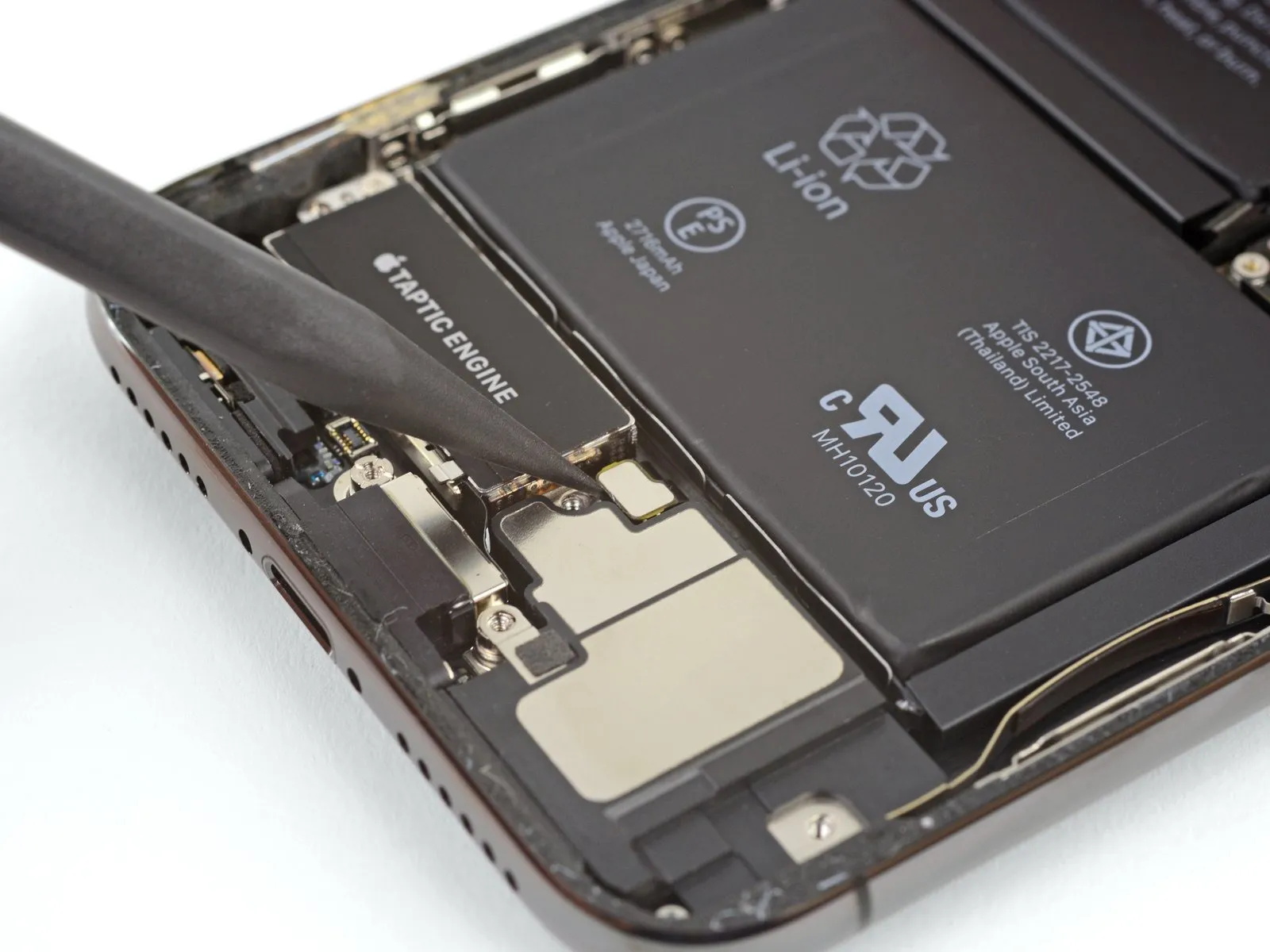
- Employ a spudger to release the Taptic Engine flex cable, lifting it vertically away from its connector.
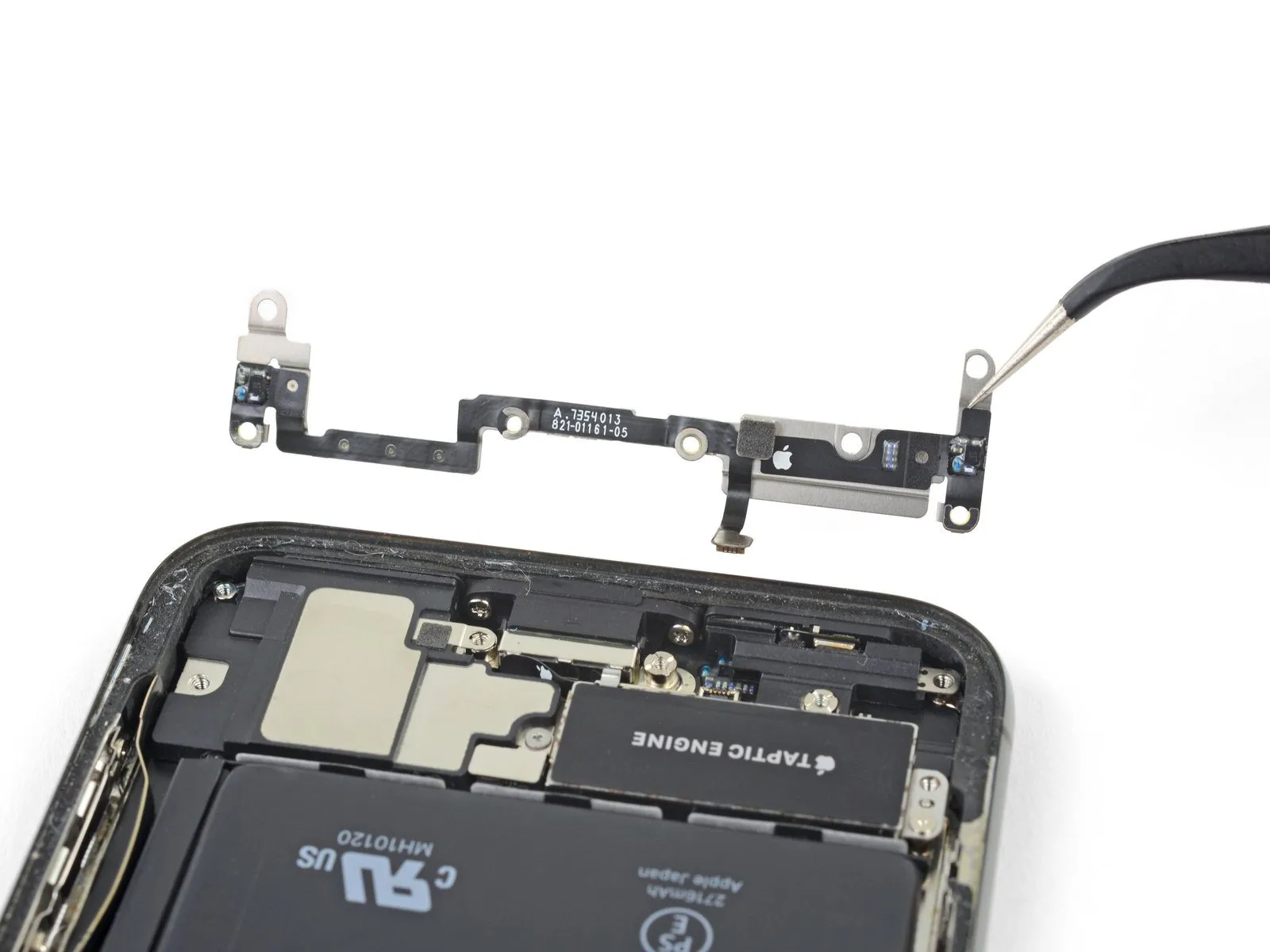
Step 39
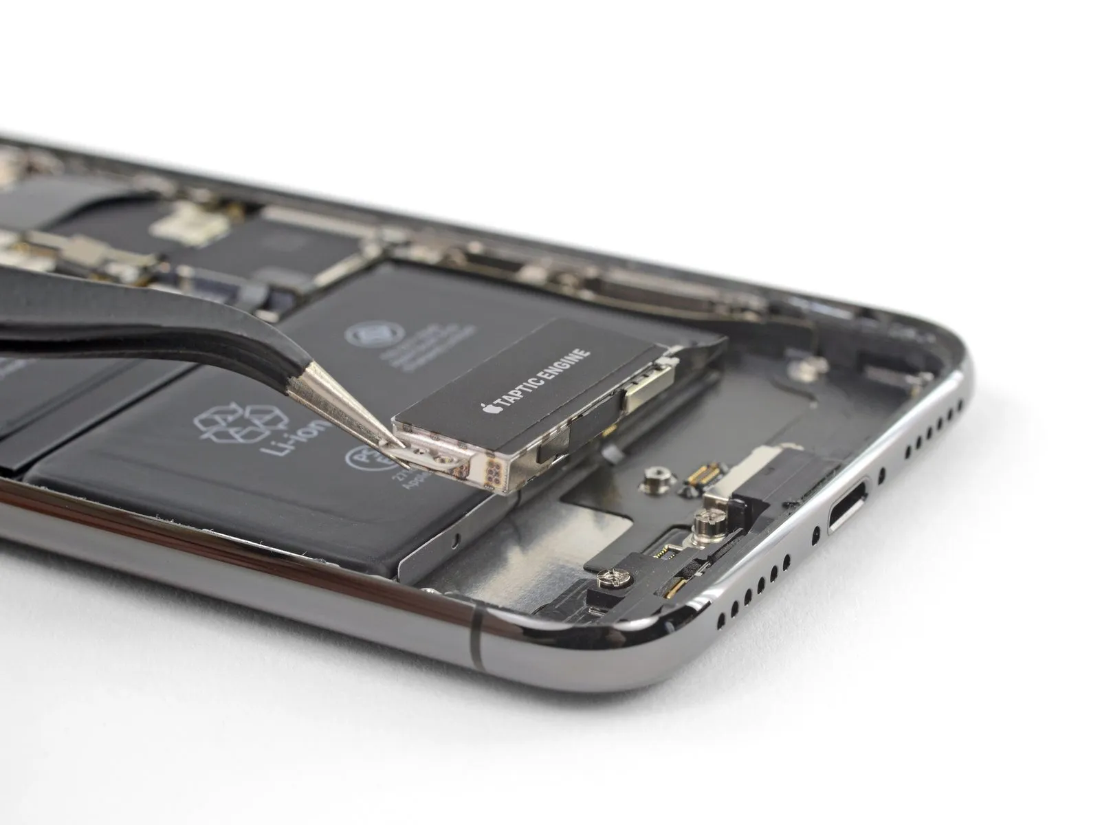
- Detach the Taptic Engine component.
Step 40 | Battery
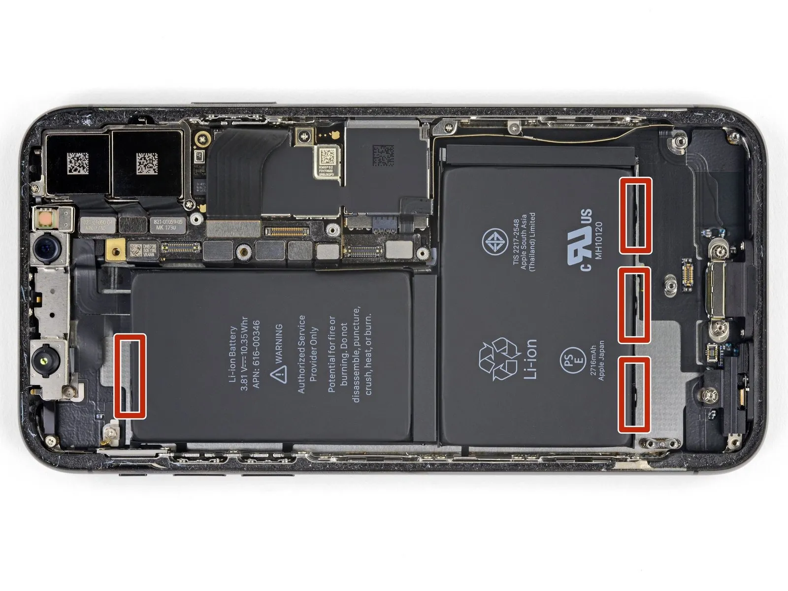
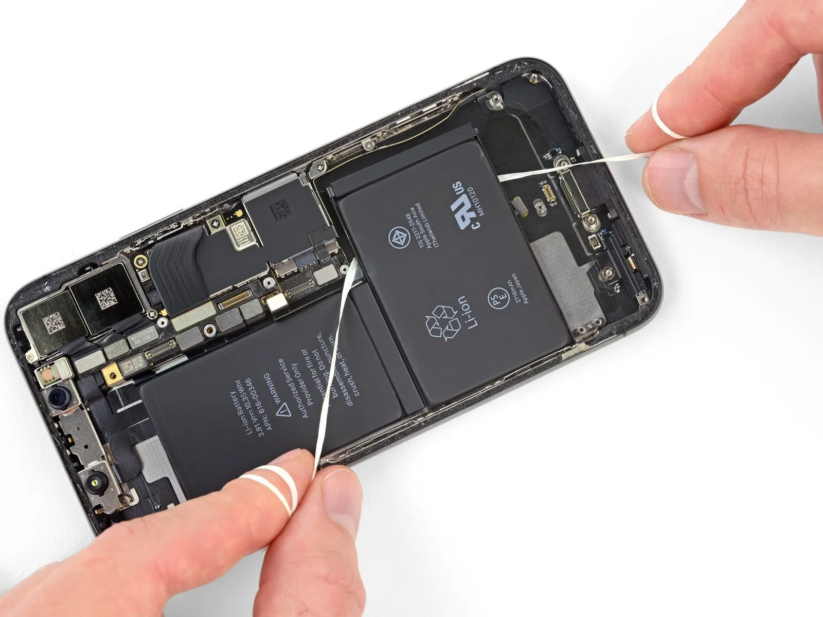
Four strips of stretch-release adhesive fasten the iPhone X's battery to the back cover; specifically, one secures the upper battery cell, while three affix the lower portion.
Step 41
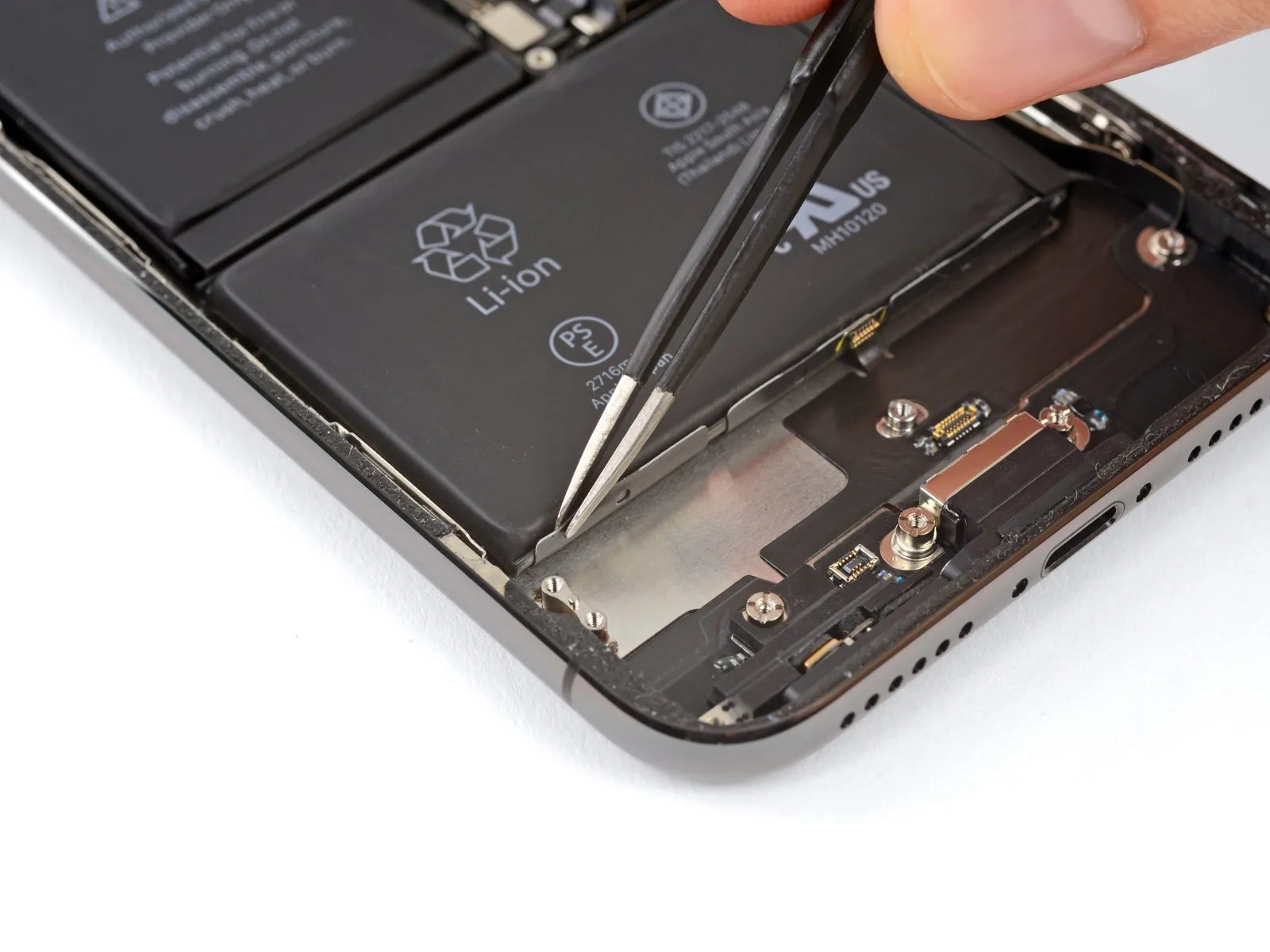
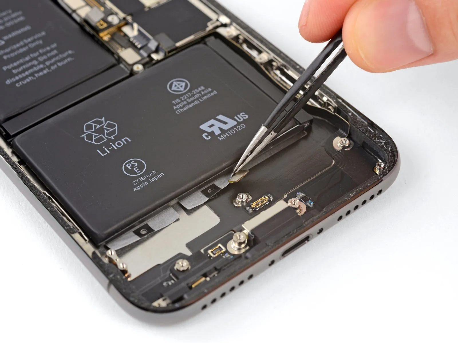
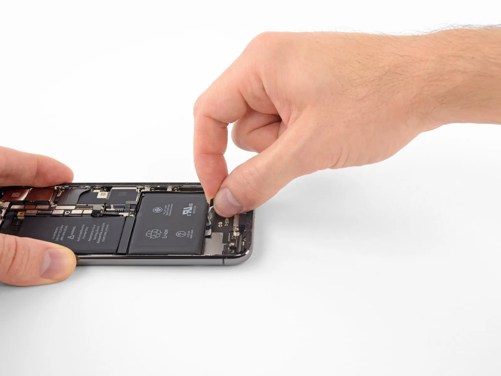
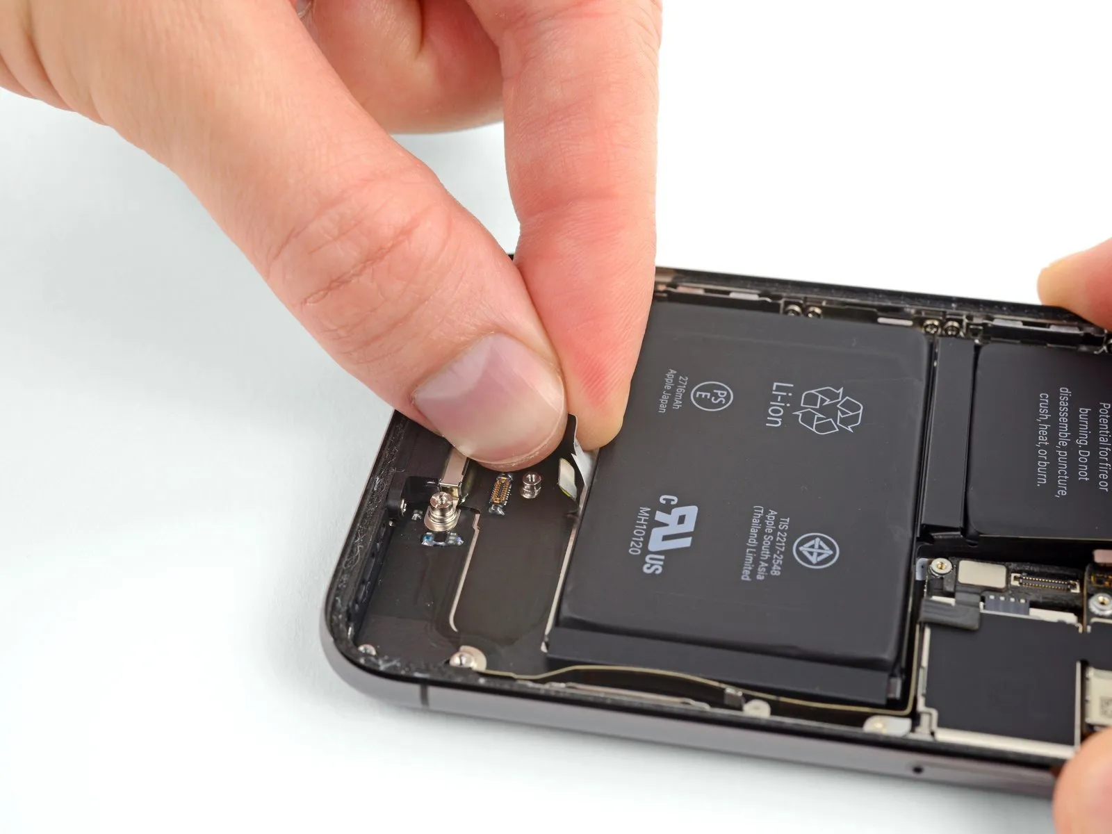
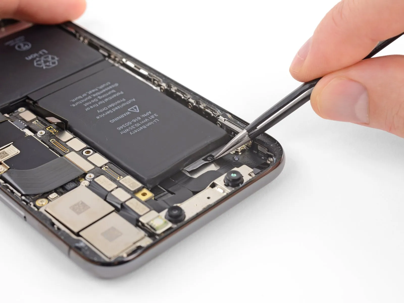
- Detach the initial battery adhesive tab from the battery's lower border by carefully separating them.
- If grasping the tab proves difficult, utilize a specialized tool to pass through the small, central loop present on every tab.
- Exercise caution to avoid puncturing the battery with any pointed instruments, as such damage could lead to the release of hazardous substances or potentially cause a fire.
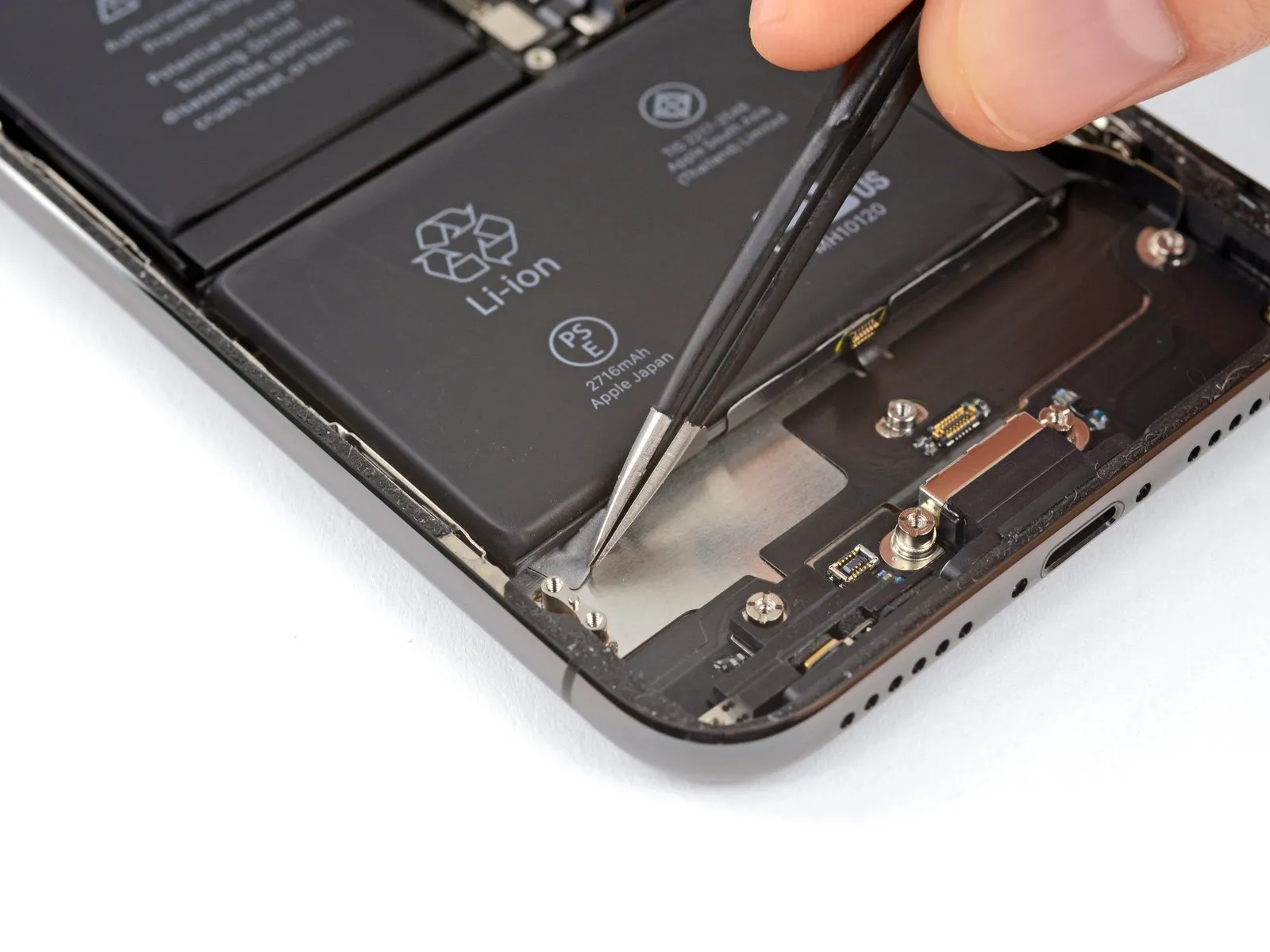
Step 42
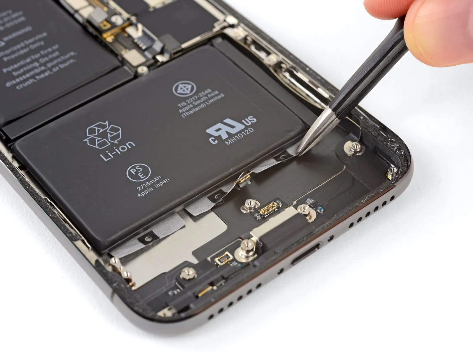
- To detach the remaining two adhesive strips, perform the previously described procedure once more, ensuring they are fully released from the battery's lower border.
- Exercise caution to prevent any harm to the speaker cable connector, which is situated immediately beneath the central adhesive tab.
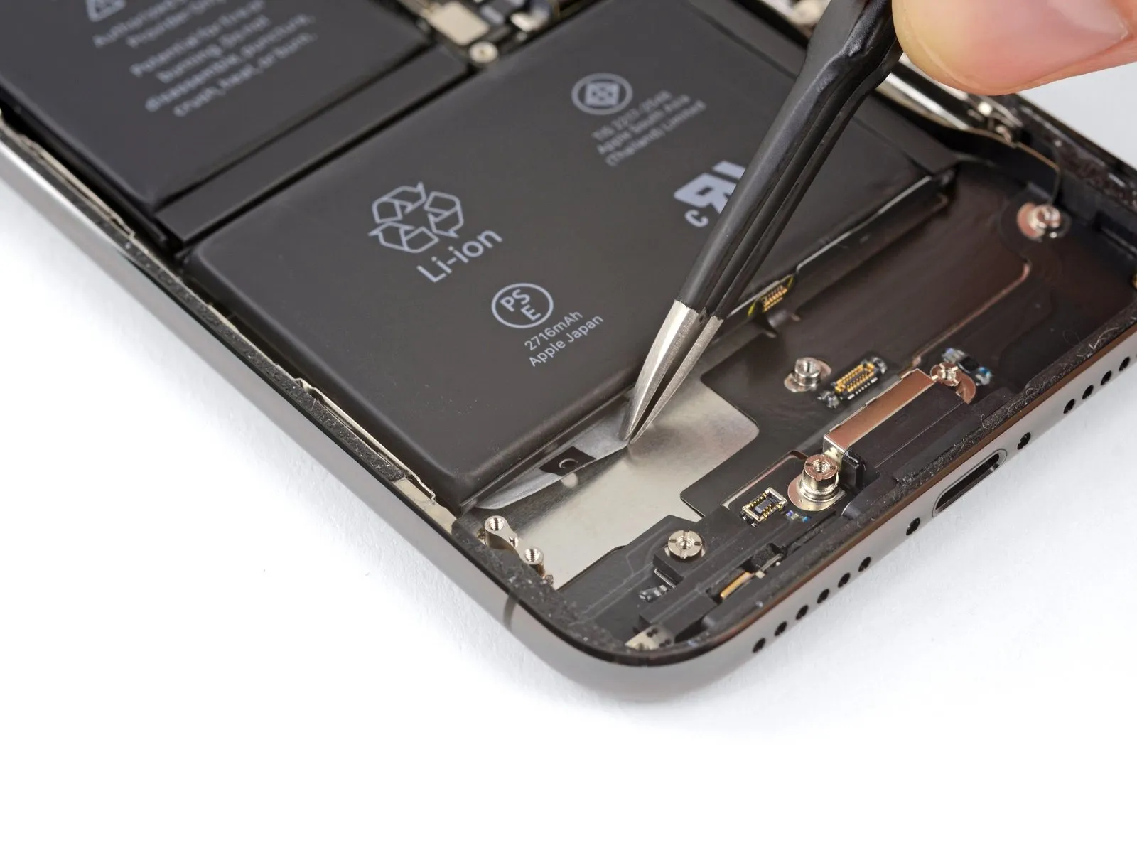
Step 43
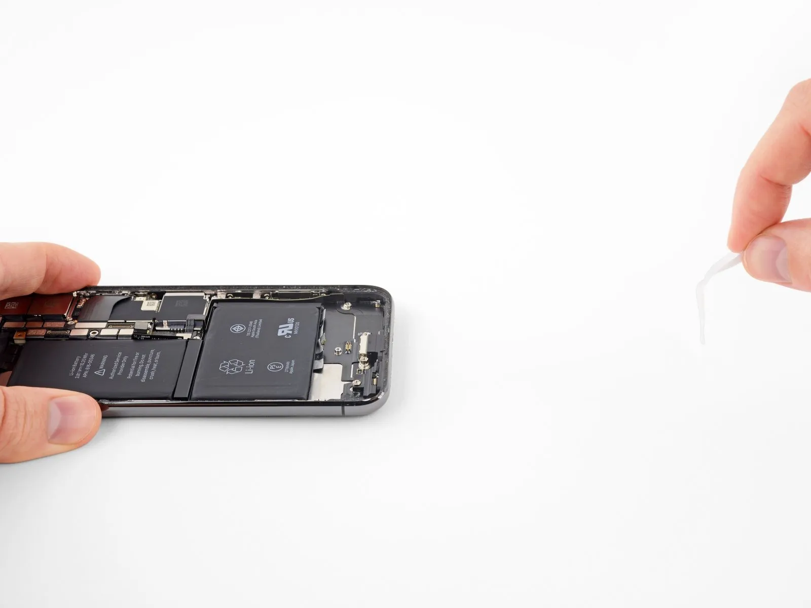
The subsequent instructions detail how to gradually extend each adhesive tab by carefully separating it from beneath the battery; this unique stretch-release adhesive diminishes its stickiness when extended, subsequently detaching from the device and enabling effortless battery removal.
Should any of the strips fracture during the process, remain composed, as they are not guaranteed to function perfectly; proceed to the subsequent instructions for alternative battery removal techniques.
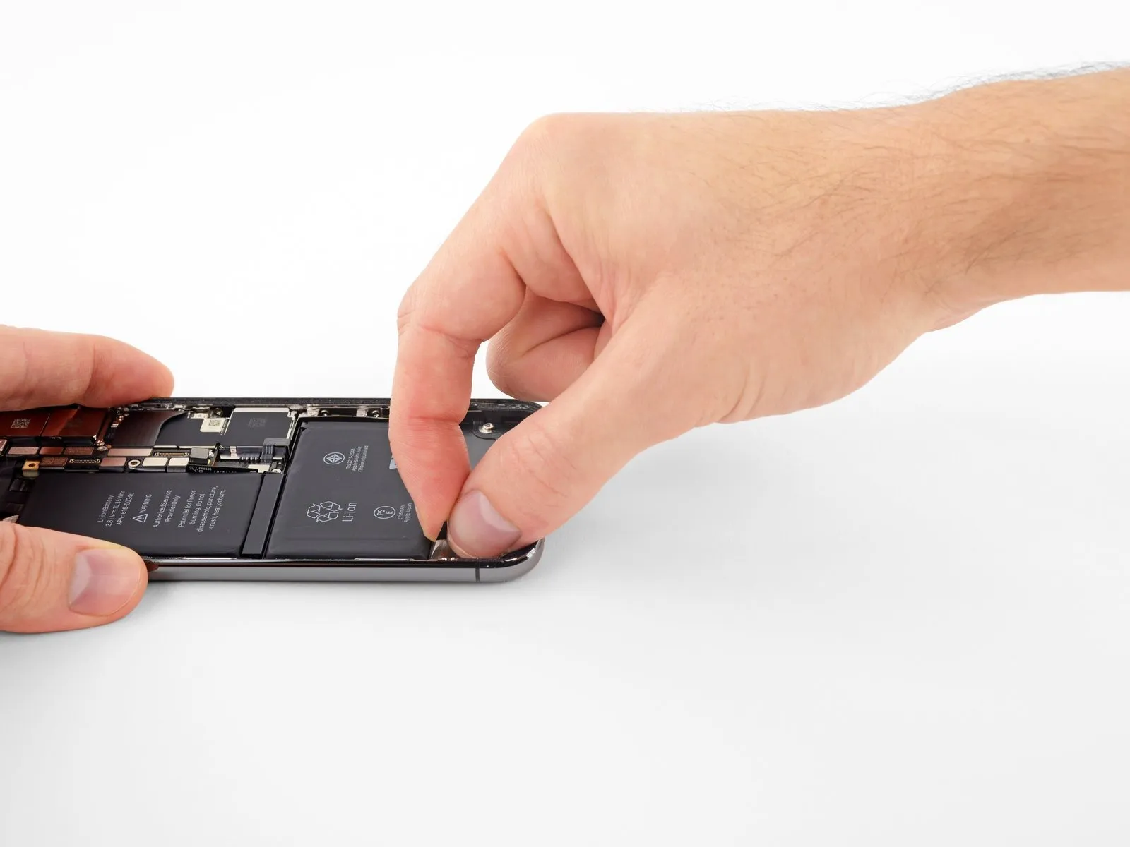
To maximize the likelihood of a successful outcome:
Avoid applying downward pressure on the battery; instead, maintain a secure grip on the iPhone's sides.
Ensure the strips remain smooth and without creases while pulling.
Exercise extreme caution and pull with deliberate slowness, allowing sufficient time—approximately 15 to 30 seconds—for each strip to extend and detach.
Maintain a shallow pulling angle to prevent the strip from catching on the battery's lower edge.
Should a strip break and become lodged beneath the battery, making retrieval impossible, proceed to the remaining strips and then follow the additional instructions provided afterward.
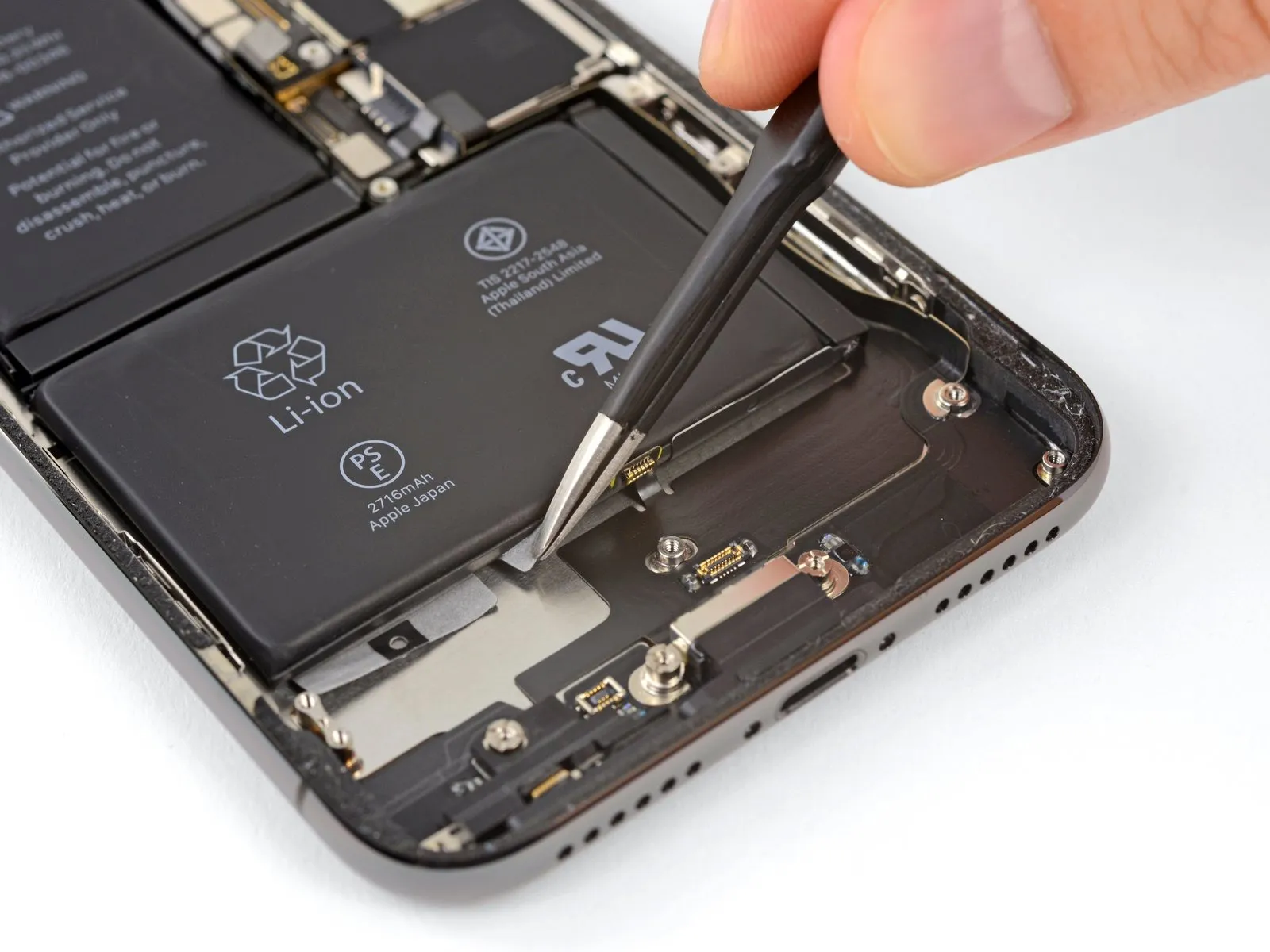
Step 44
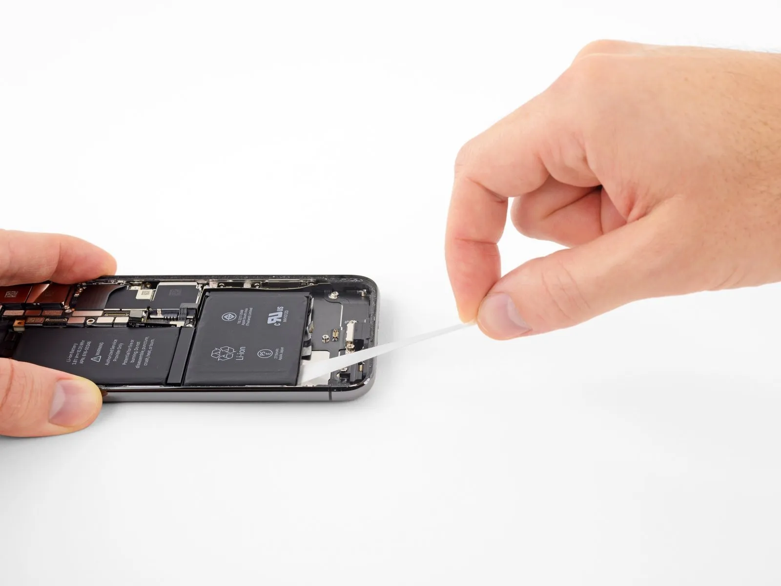
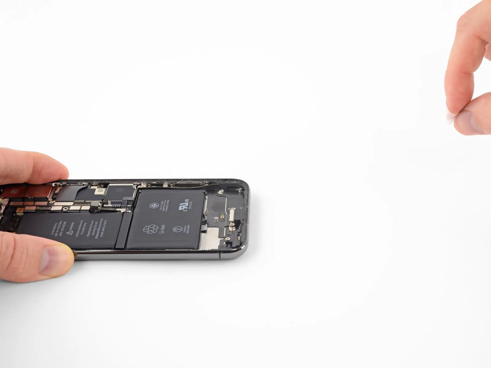
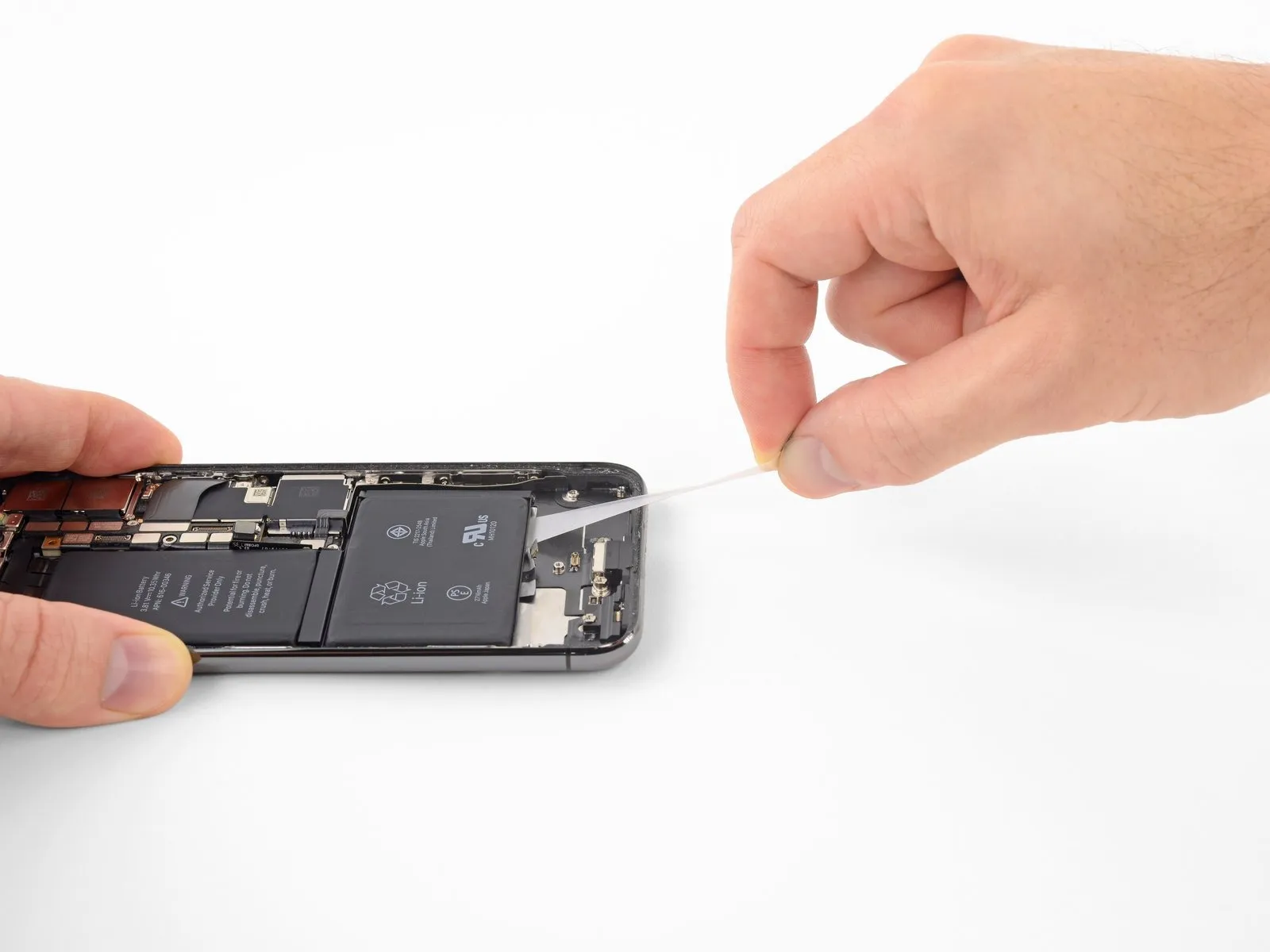
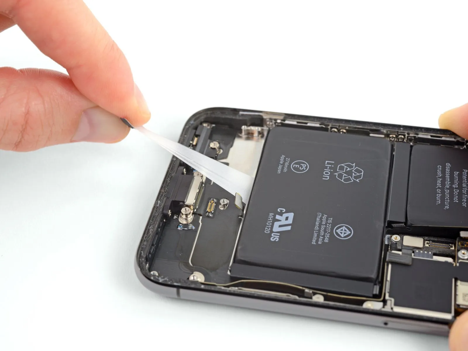
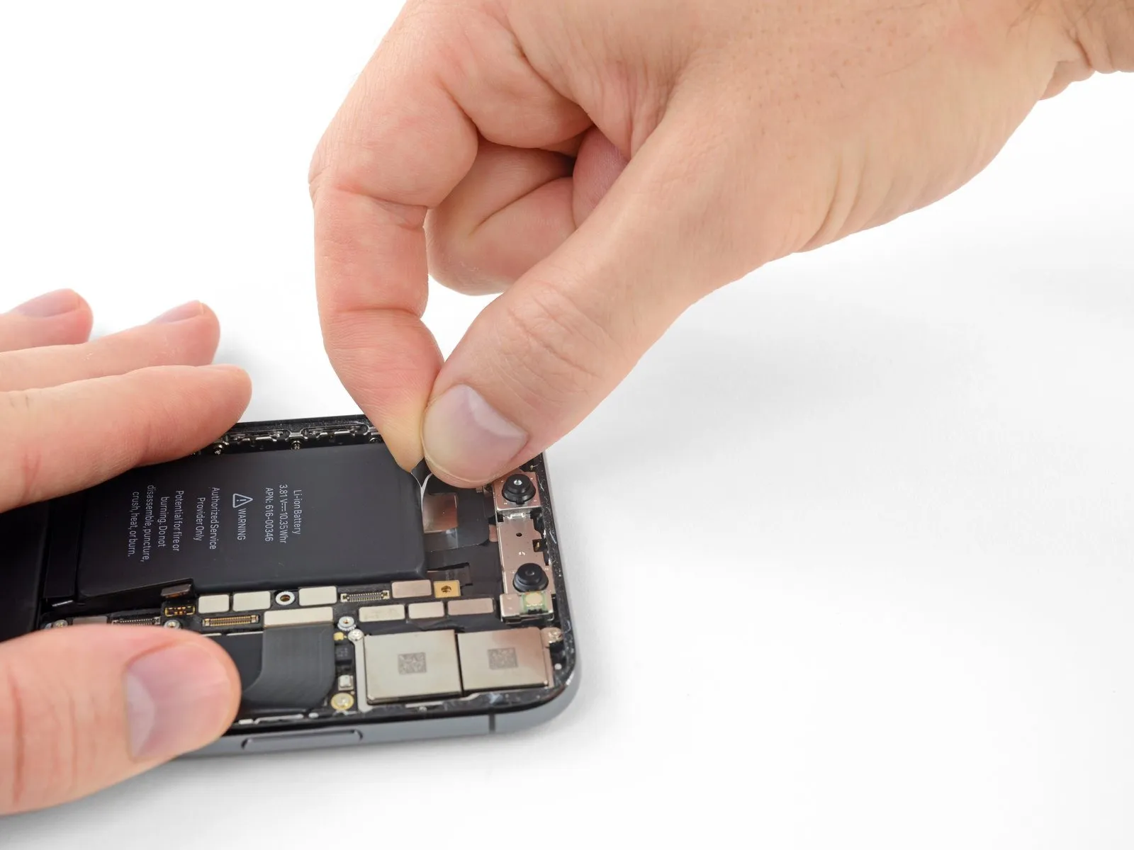
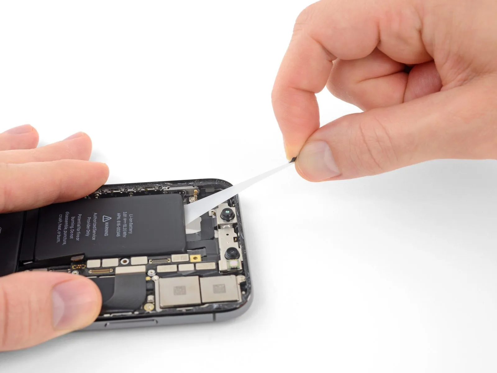
- Carefully detach one of the external battery adhesive strips by gently drawing it away from the battery surface, directing its movement towards the lower portion of the iPhone’s chassis.
- Maintain a consistent, even force as you pull the strip, ensuring it remains taut until it disengages from the space between the battery and the rear enclosure.
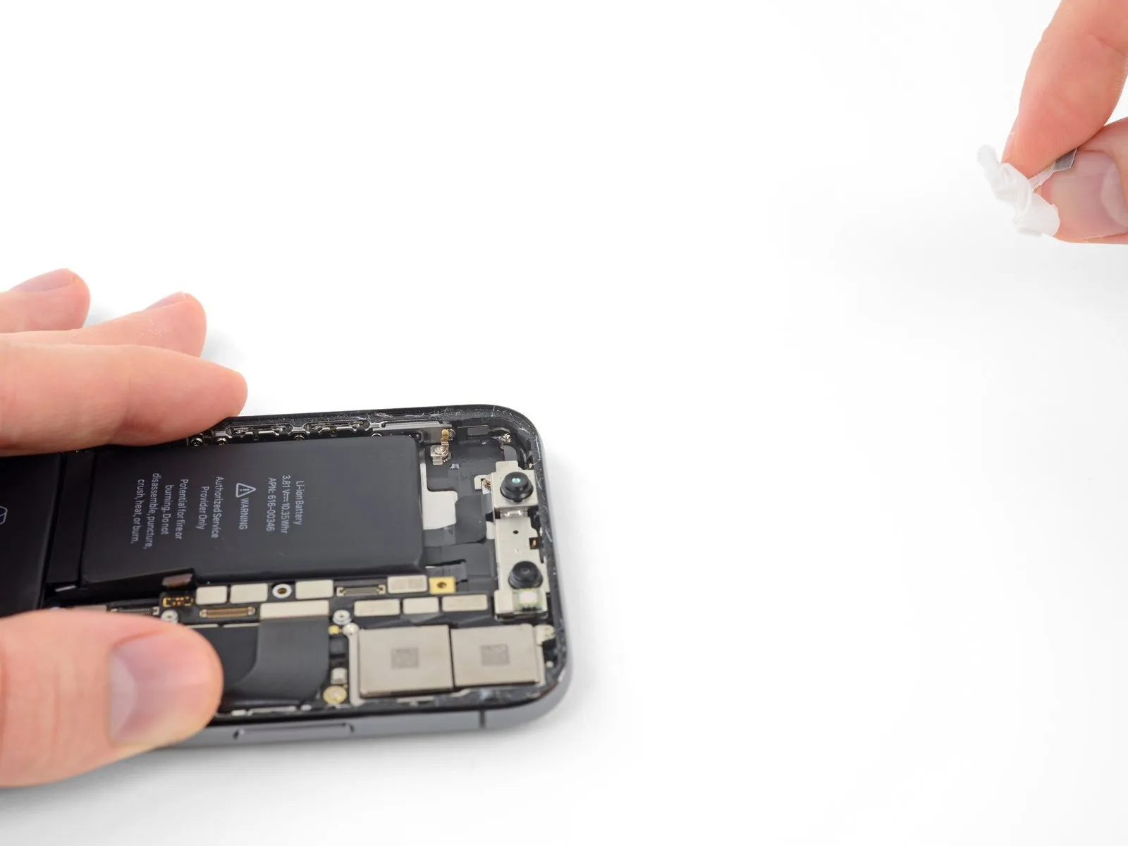
- Expect the adhesive strip to elongate significantly, potentially stretching to several times its initial size; persist in pulling and reposition your grip along the strip’s length near the battery as needed.
- Should any of the battery adhesive strips tear during removal, utilize your fingers or non-piercing tweezers to recover the detached adhesive fragments and continue the extraction process.
- In the event that adhesive strips fracture beneath the battery and are inaccessible, attempt to remove the remaining strips and then follow the subsequent instructions.
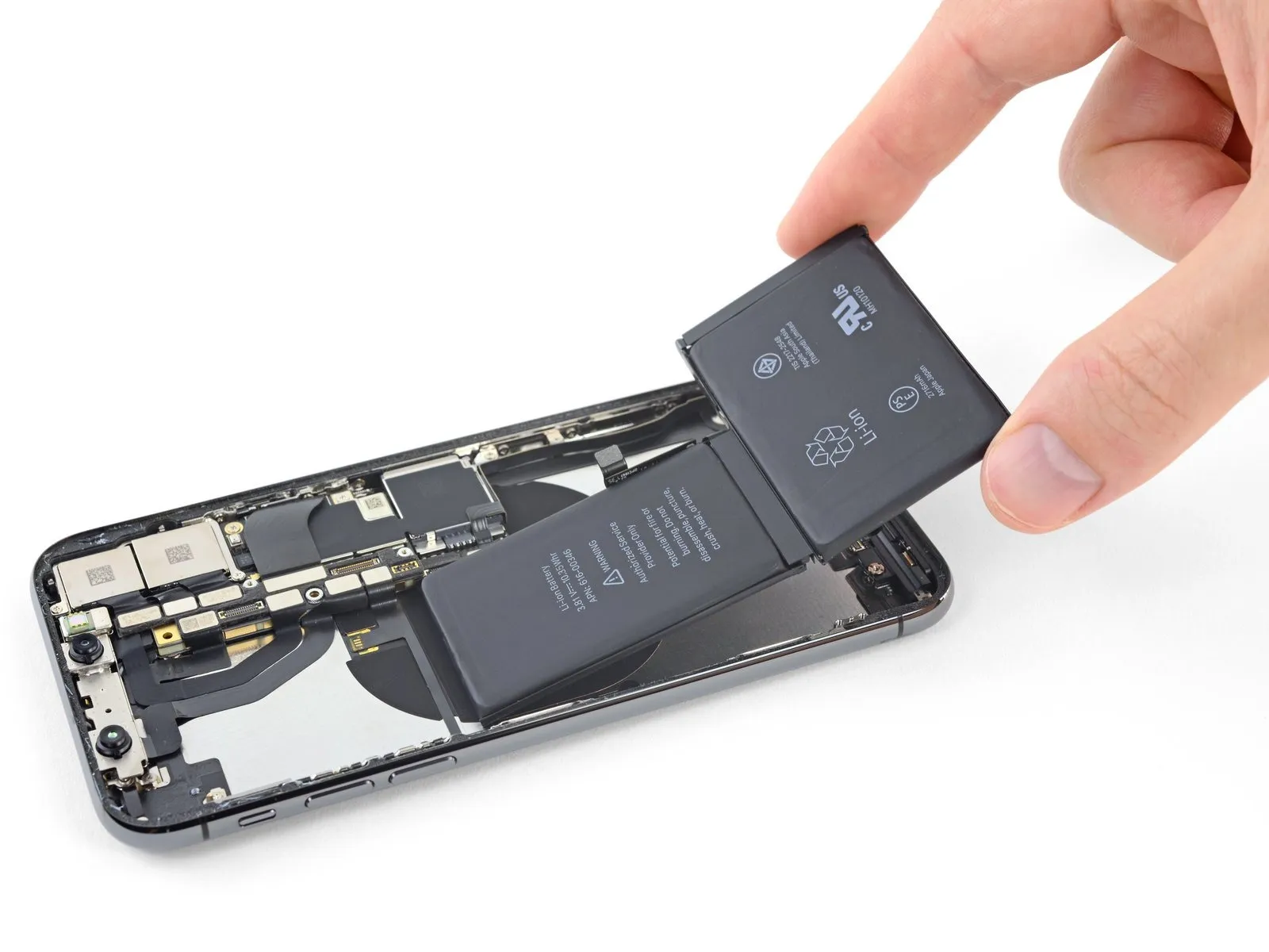
Step 45
Step 46
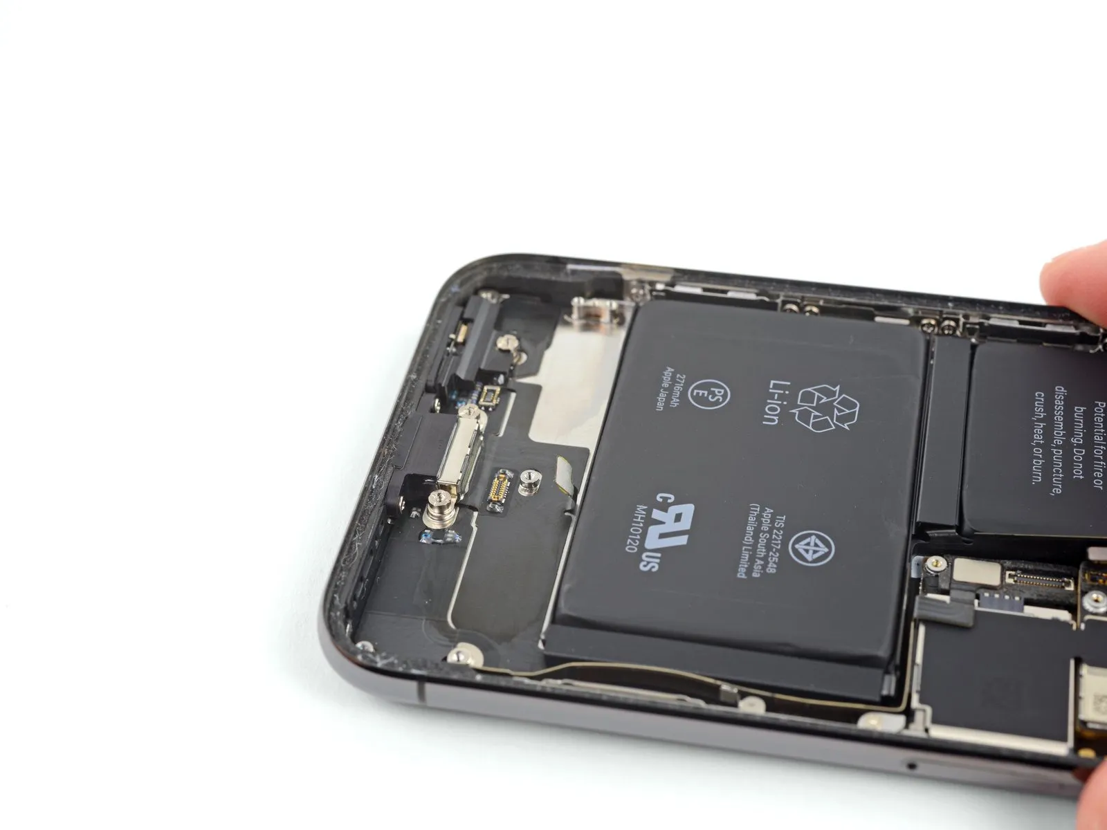
- Detach the central portion of the component.
Step 47
- The last retaining tab is situated in immediate proximity to the Face ID components, and any harm to it necessitates extreme caution.Due to the complexity of the system, Face ID functionality can exclusively be restored by Apple technicians.Proceed with meticulous attention to detail to prevent unintended damage.
- Carefully lift and detach the pull tab from the uppermost adhesive strip, which is positioned along the superior border of the upper battery cell.
Step 48
- Carefully detach and eliminate the last adhesive strip.
- During separation, the strip’s release could propel the battery from the iPhone; therefore, position your hand above the battery to stabilize it, but avoid applying downward pressure, as this may cause the adhesive strip to fracture and remain beneath the battery.
- Should you have successfully removed all four adhesive strips, proceed past the following instruction.
- In the event that fragments of the adhesive remain adhered to the battery and are inaccessible, introduce a small quantity of isopropyl alcohol with a concentration exceeding 90% beneath the battery’s edge, specifically targeting the location of the detached adhesive strip(s).
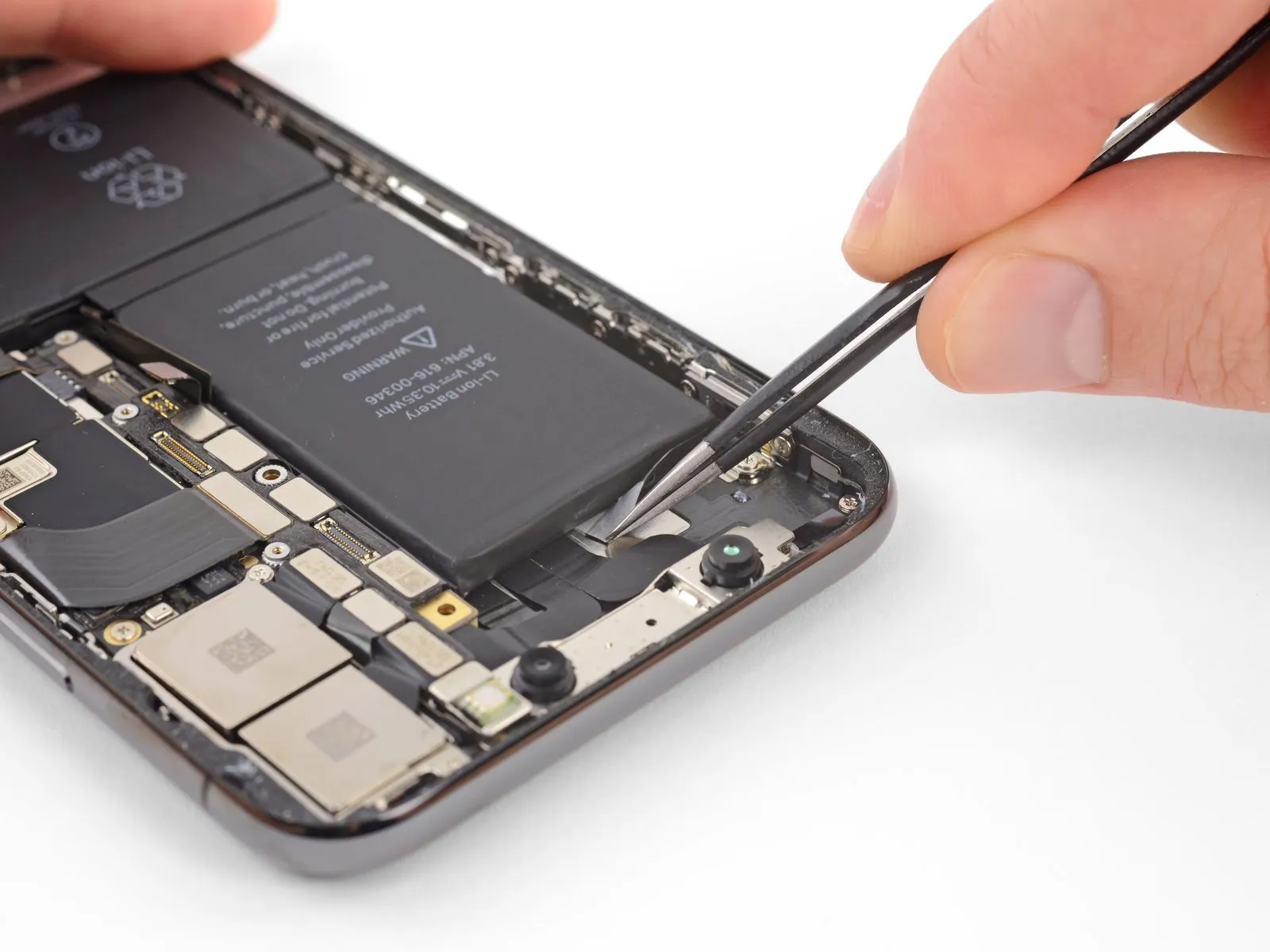
- Allow approximately one minute for the alcohol to diminish the adhesive’s strength. Subsequently, utilize the planar end of a spudger to delicately raise the battery.
- Refrain from employing excessive force to dislodge the battery; if resistance is encountered, introduce additional drops of alcohol to further reduce the adhesive bond. Under no circumstances should the battery be deformed or perforated by your tool.
- Exercise caution to prevent damage to the flexible ribbon cables and the wireless charging coil situated directly beneath the battery.
Step 49 | Alternative method to unstick the battery from the case
- Should any of the adhesive strips detach and the battery remain adhered to the rear case, ready an iOpener or employ a hair dryer to apply heat directly to the rear case's area behind the battery.
- Warm the iPhone until the rear case reaches a temperature that is slightly uncomfortable to touch, exercising care to avoid overheating, which could potentially cause battery ignition.
- Turn the iPhone over and carefully insert a durable string—such as dental floss or a slender length of guitar string—beneath the battery.
- Protect your fingers by wrapping the string's ends around a cloth or by utilizing gloves.
- Employ a sawing motion, moving the string from side to side across the battery's entire length, to sever the adhesive bond; this process may require considerable time due to the adhesive's slow yielding characteristics, but persistence will result in its release, ensuring the battery remains undamaged.
- Should you opt to utilize prying implements to extract the battery from the iPhone, exercise utmost caution to prevent harm to the delicate ribbon cables or the wireless charging coil situated directly beneath the battery.
Step 50
- Securely hold the battery from its lower edge and detach it from the iPhone's internal structure.
- To prevent potential issues, thoroughly eliminate any residual alcohol solution from within the device, either by wiping it away gently or permitting it to evaporate completely, prior to installing the new battery.
- Prior to installing the replacement battery, ensure the Taptic Engine and speaker are reinstalled. Maintaining this order assists in ensuring correct battery alignment during the installation process.
- To guarantee proper positioning within its designated space, briefly reconnect the battery connector to the logic board socket before securing the replacement battery.
- Attach the replacement battery, then disconnect it, and proceed with the remaining reassembly steps for your device.
- Should your new battery lack pre-applied adhesive, consult this guide for detailed instructions on replacing the adhesive strips.
- Following complete reassembly, execute a forced restart to proactively avoid potential problems and streamline any necessary troubleshooting.
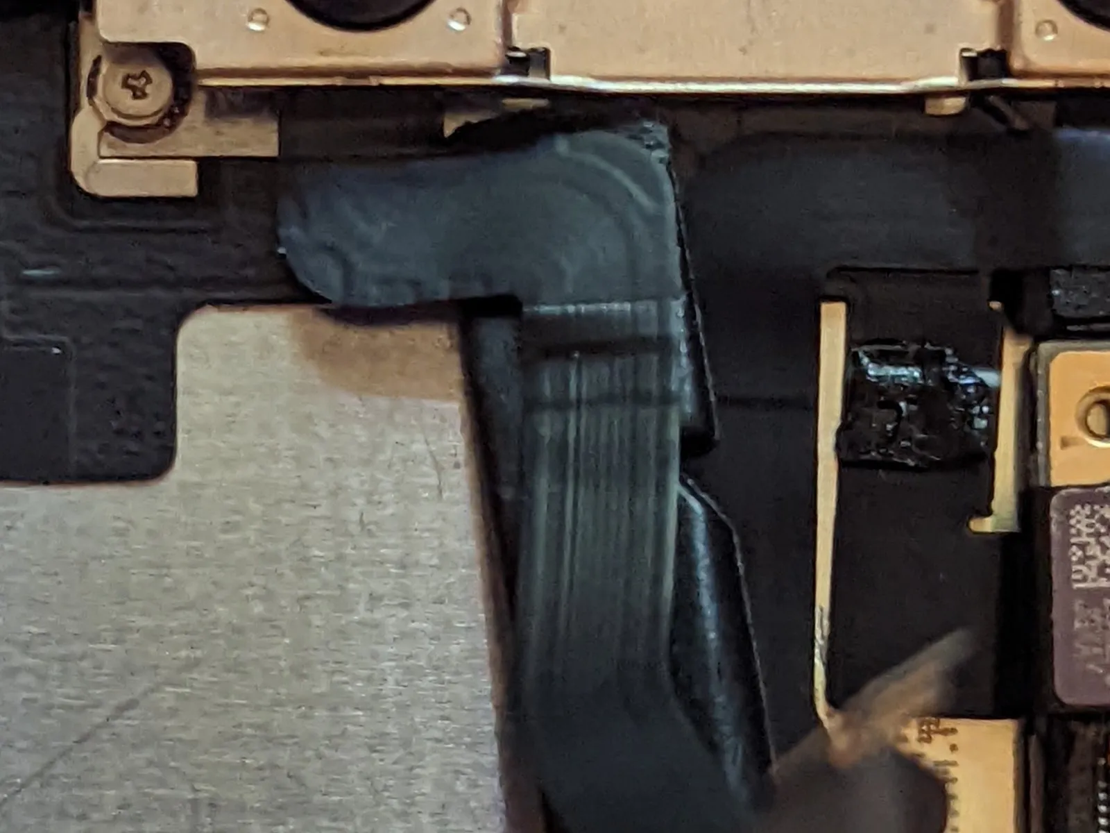
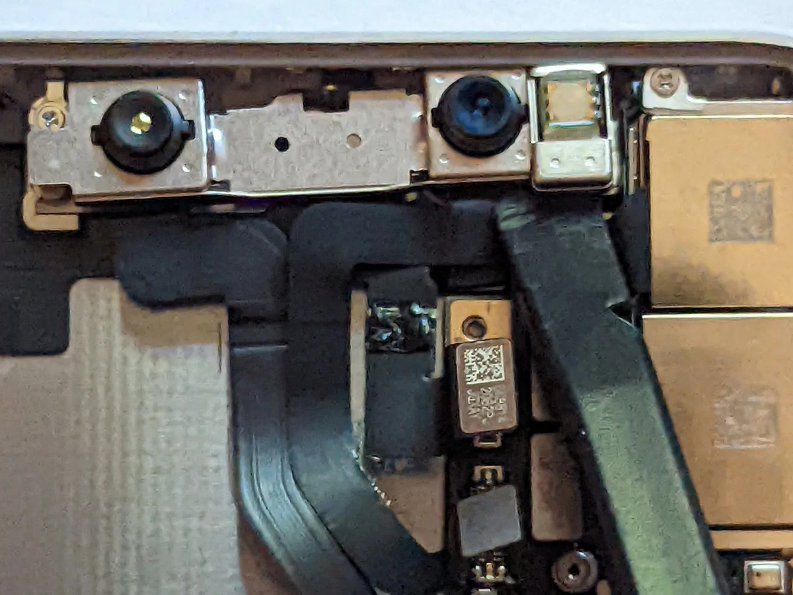
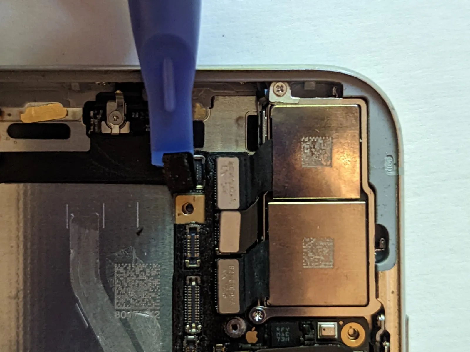
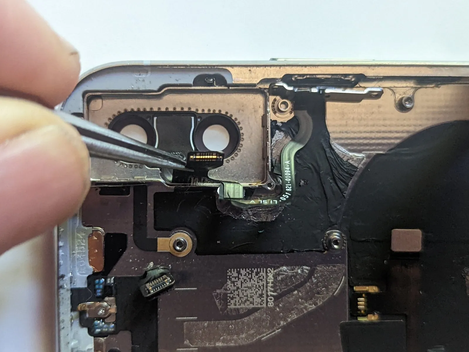
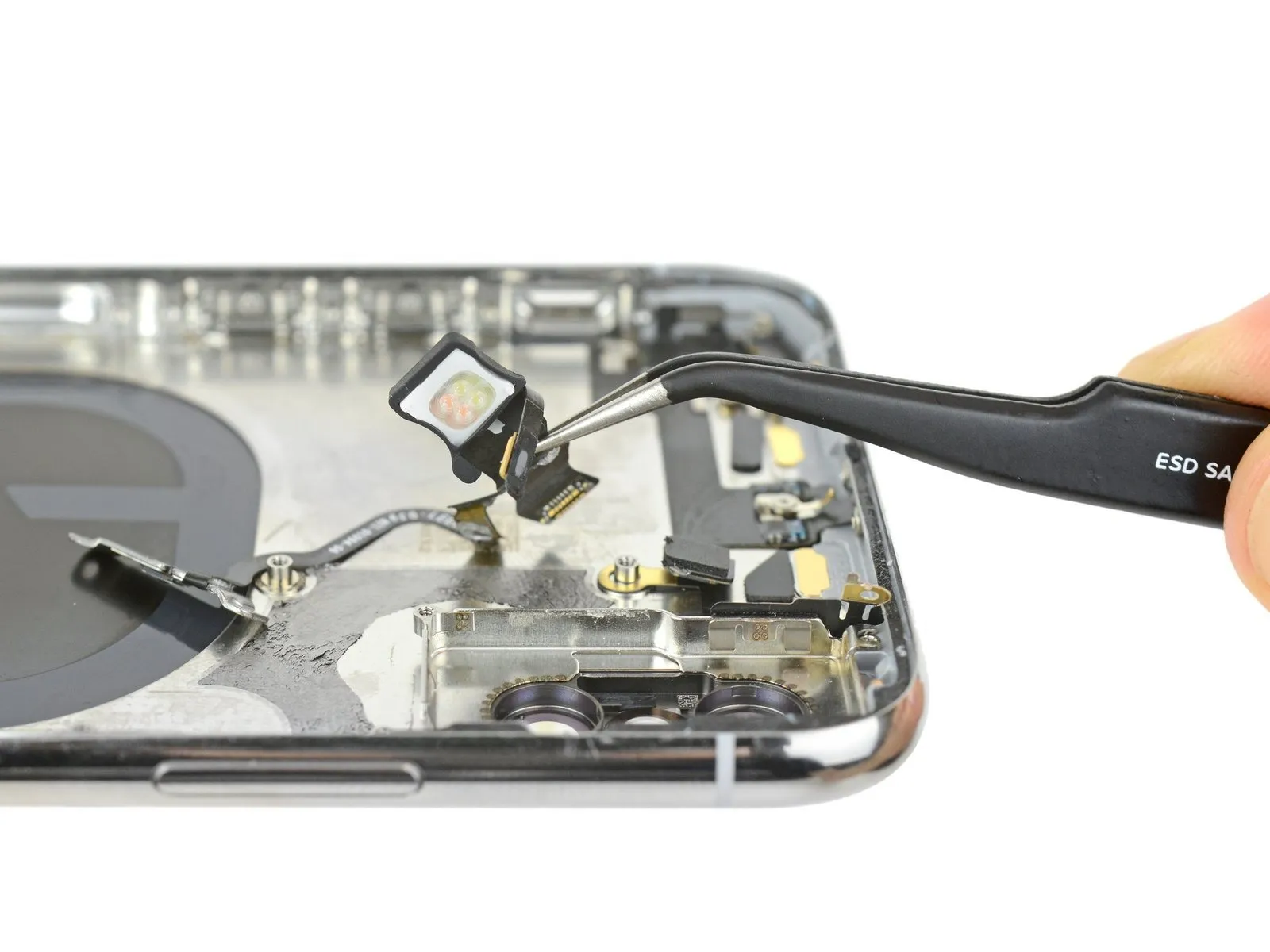
Step 51 | Front Camera Assembly


- Employing the planar edge of a spudger tool, carefully release the connectors securing the three cables linked to the front camera assembly.
• The dot projector component.
• The primary front-facing camera.
• The infrared camera module.
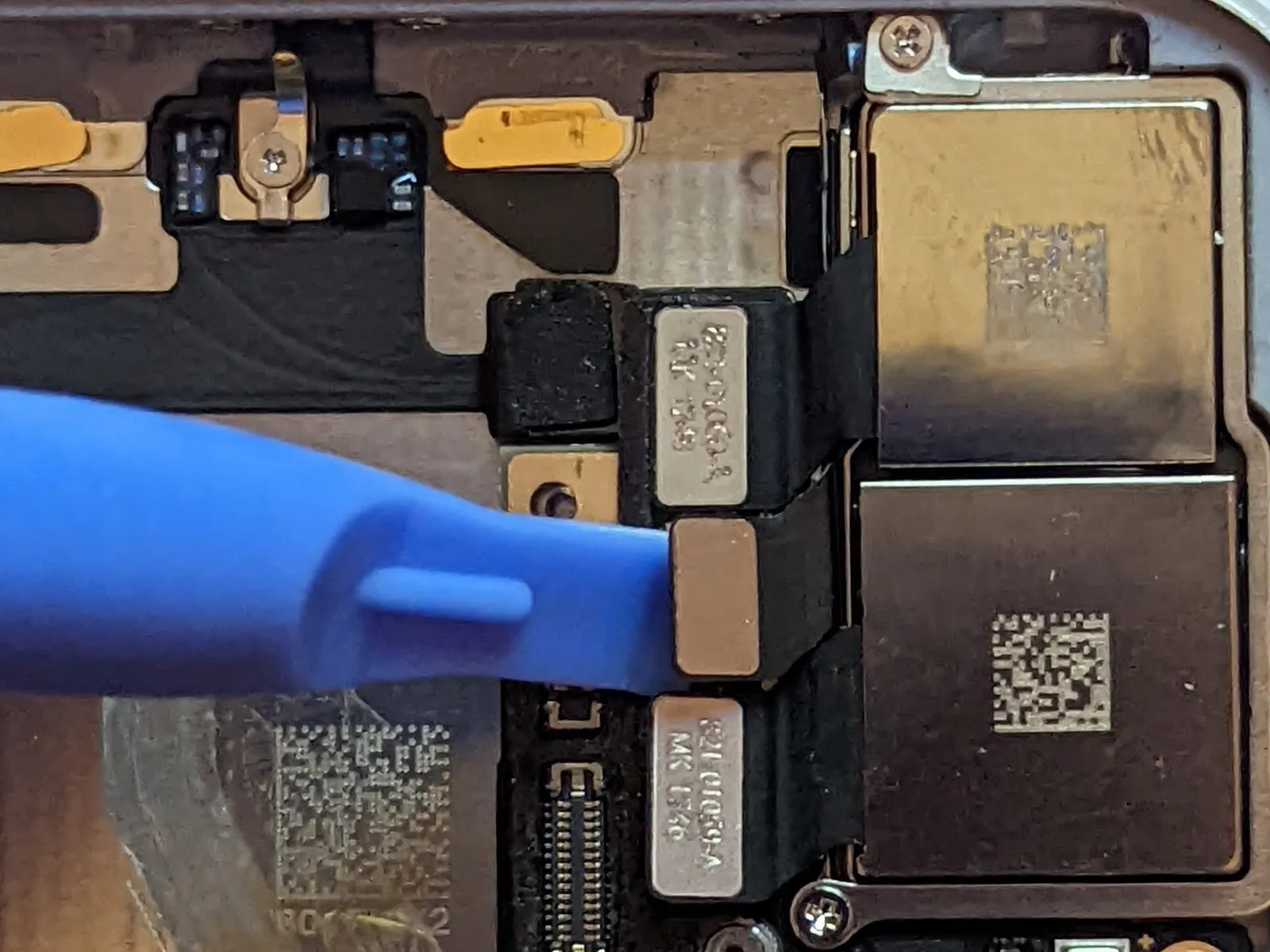
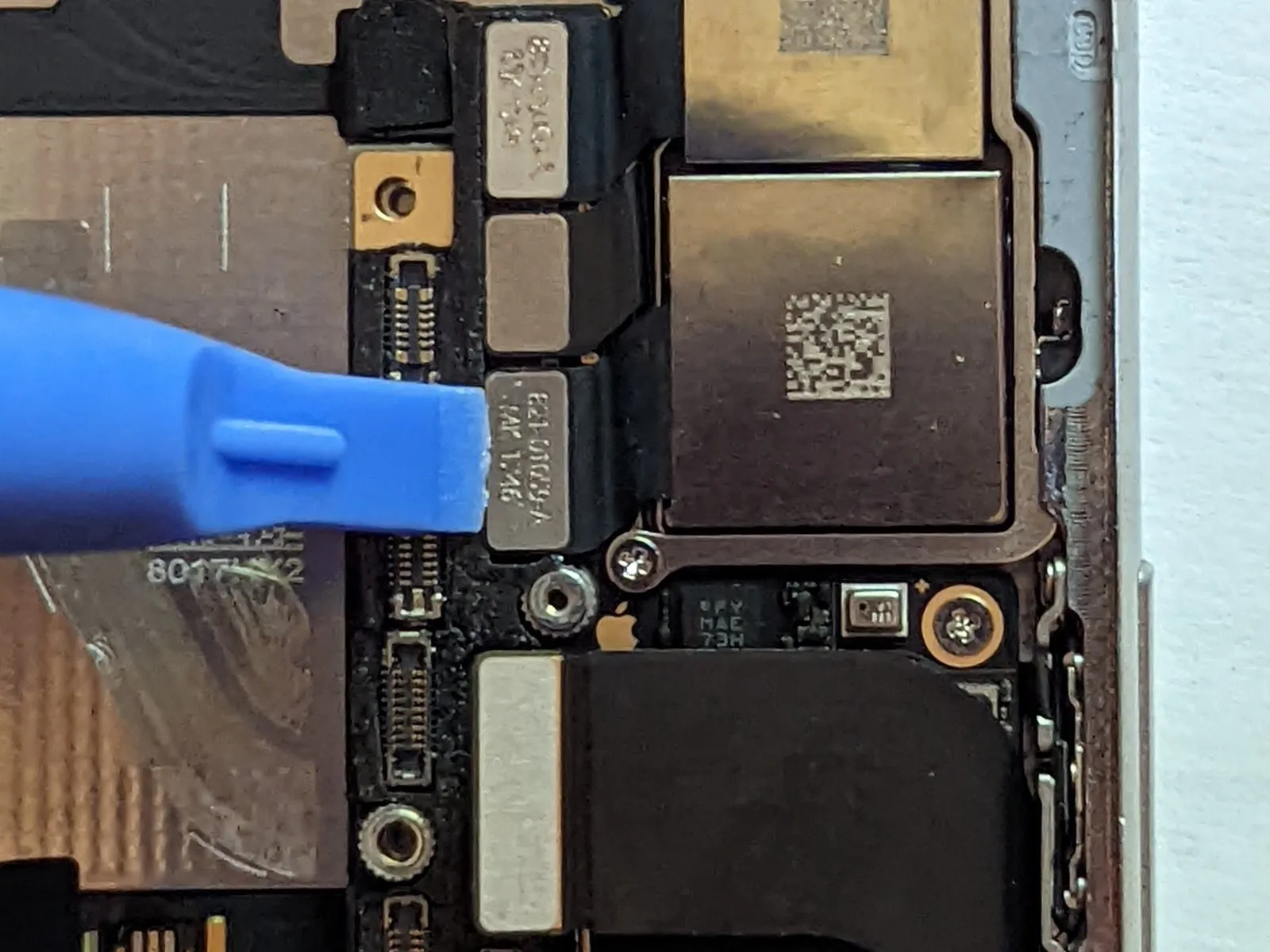
Step 52
The camera cables are affixed to the midframe with a minimal adhesive.
Employing the pointed end of a spudger, initiate the separation process at the connector location, then carefully move the spudger's tip in between the infrared camera cable and the device casing to detach the cable.
Replicate this procedure for the front-facing camera cable.
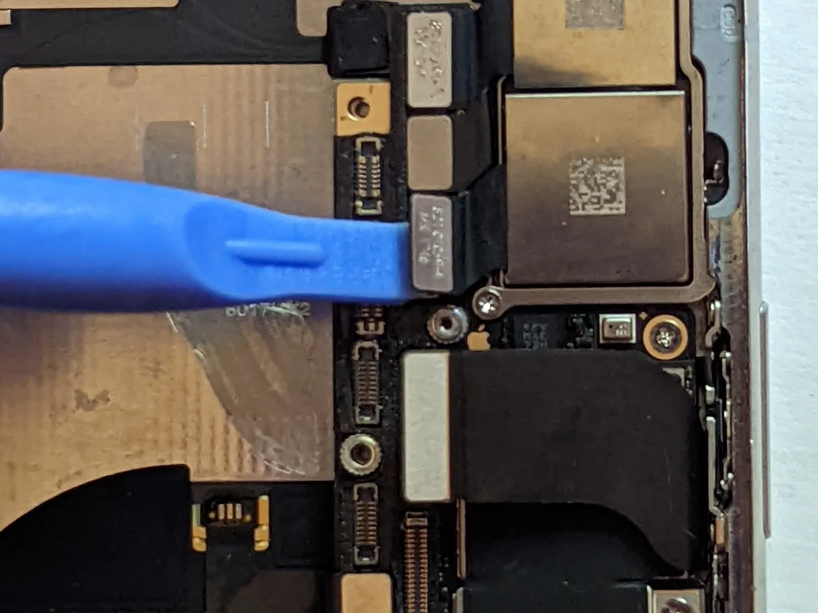
Step 53
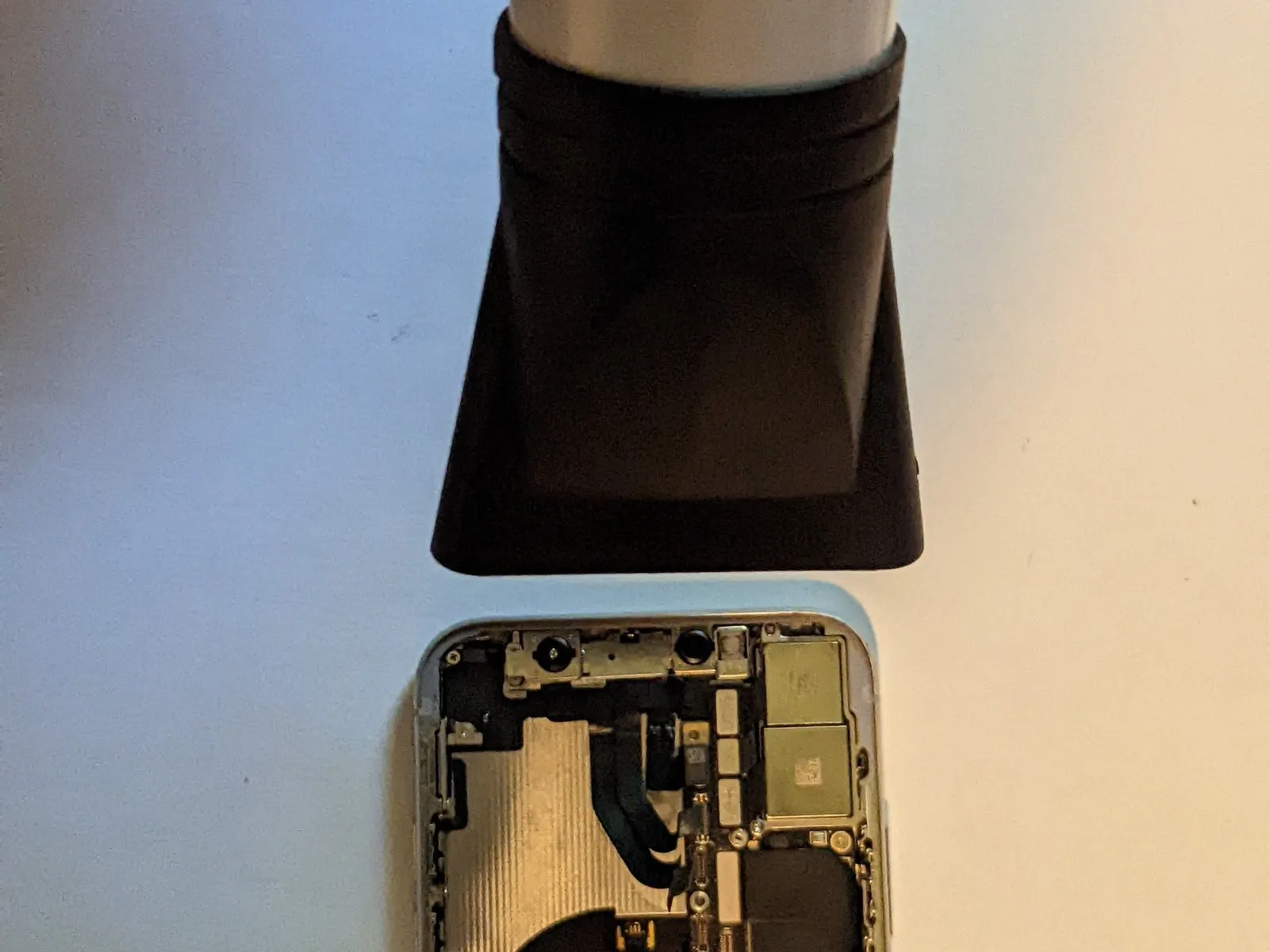
To release the bonding agent securing the front camera module, utilize a heat source.
Step 54
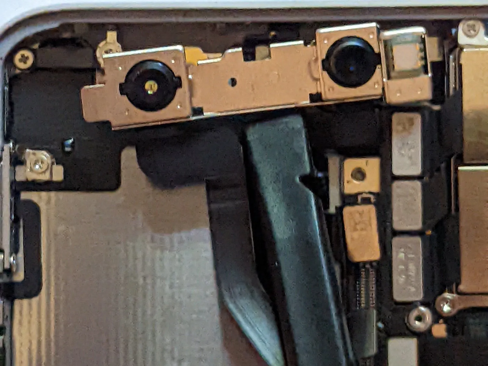
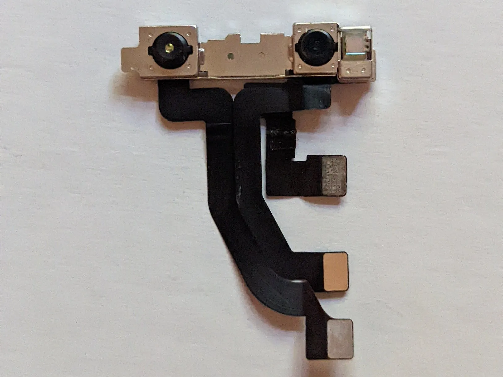
Carefully detach the front-facing camera module.
Step 55 | Logic Board
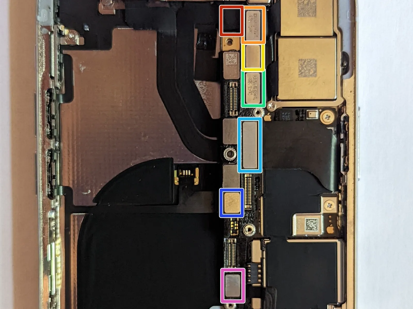
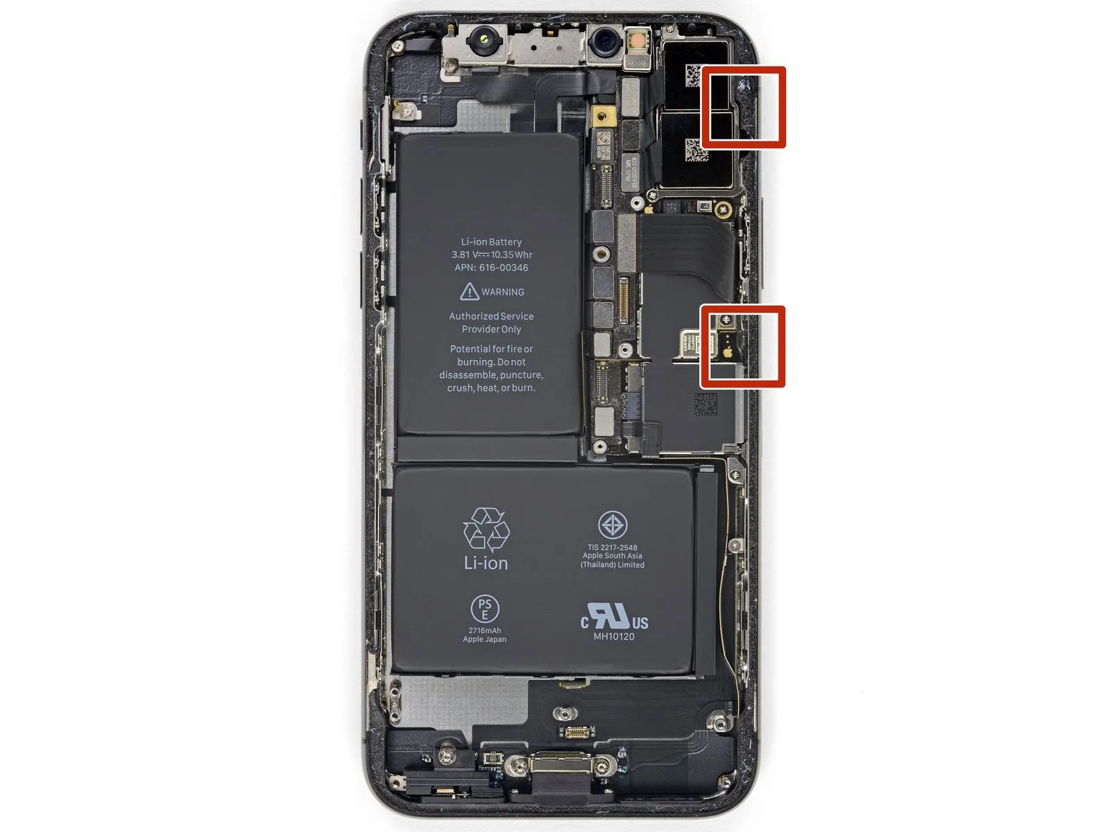
- To proceed with the repair, first, carefully detach these cable connectors:
• The WiFi Antenna connector must be disconnected.
• The Wide-Angle Camera connector requires separation.
• The Power Button / Flash / Microphone connector needs to be detached.
• The Telephoto Camera connector should be disconnected.
• The Dock Flex connector must be carefully disconnected.
• The Button / Wireless Charging connector requires separation.
• The Cellular Antenna connector needs to be detached.
Step 56 | WiFi Antenna Connector

To proceed, detach the WiFi antenna cable from its corresponding connector.
Step 57 | Wide-Angle Camera Connector

Step 58 | Power Button / Flash / Microphone Connector

Step 59 | Telephoto Camera Connector
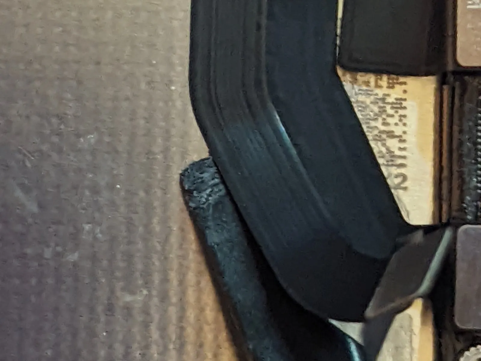
Step 60 | Dock Flex Connector
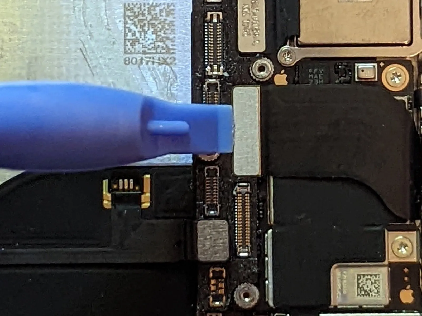
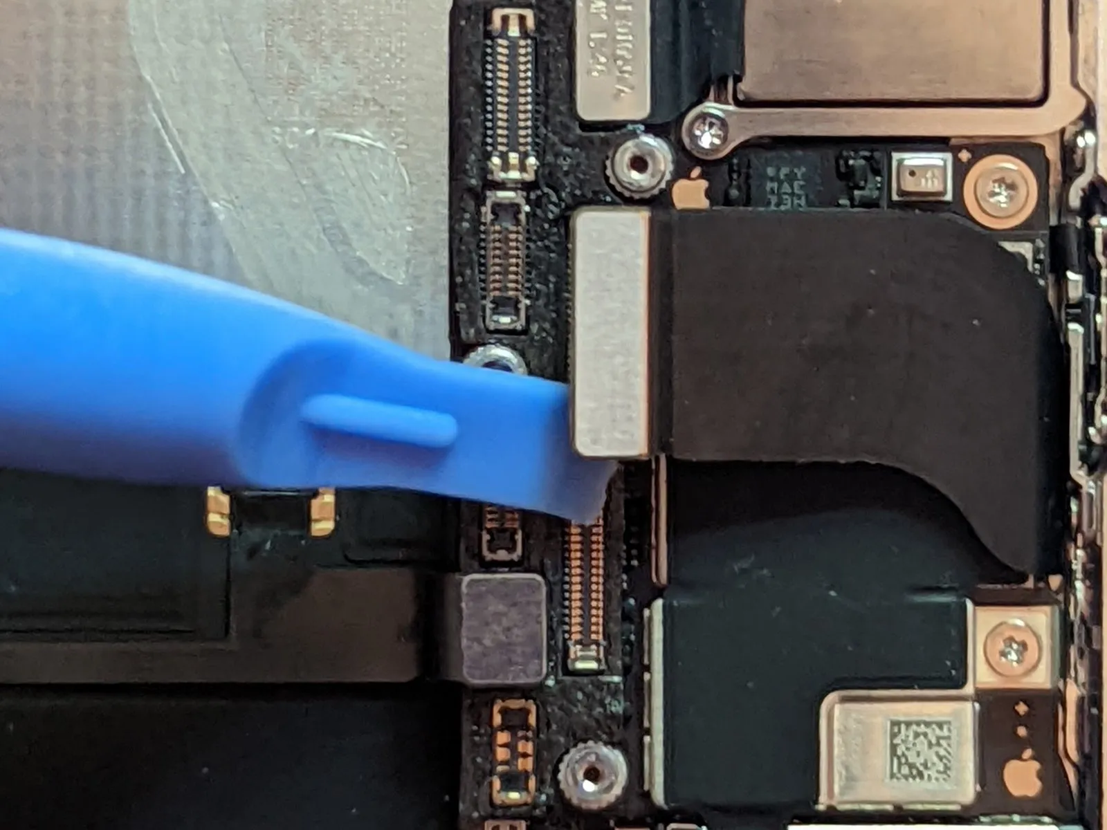
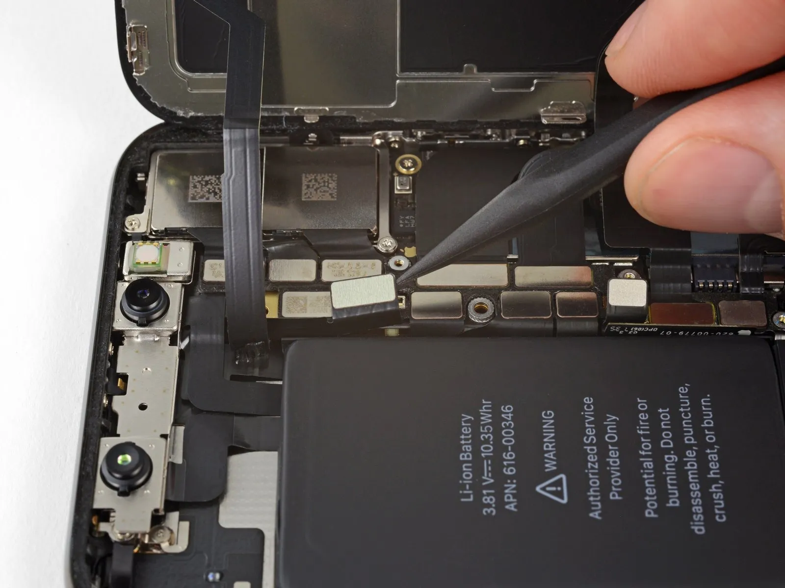
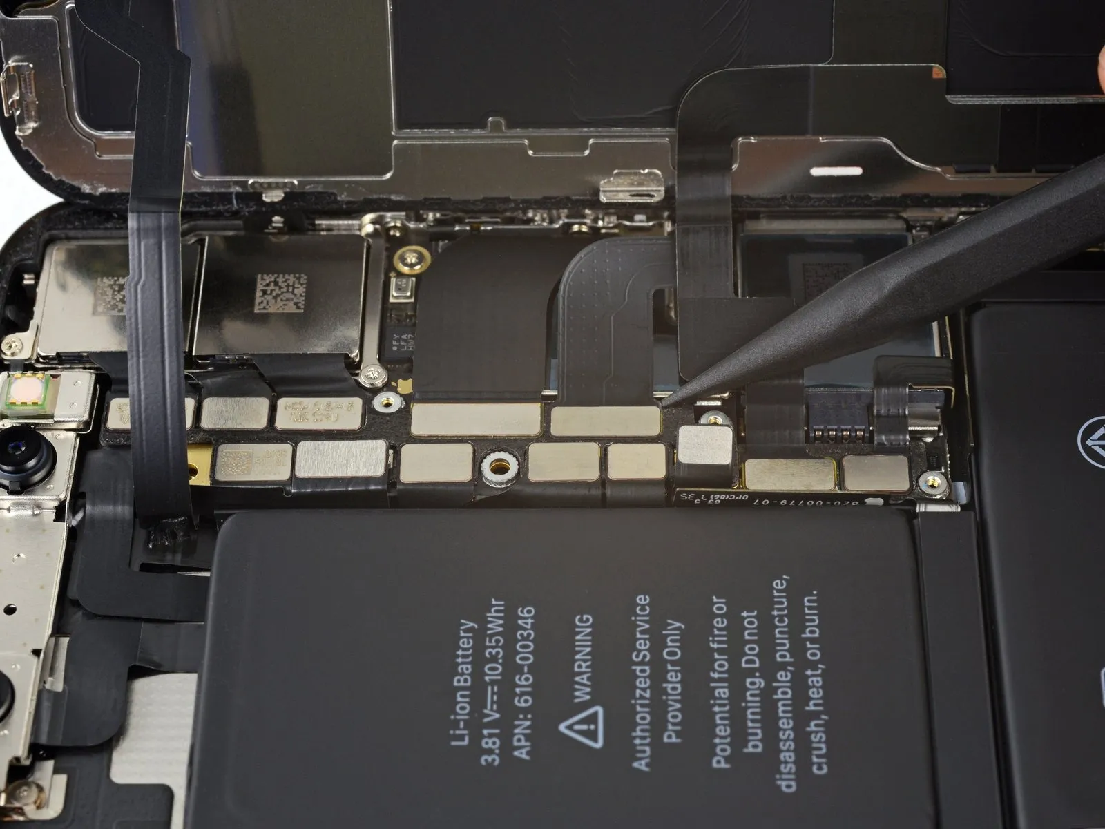
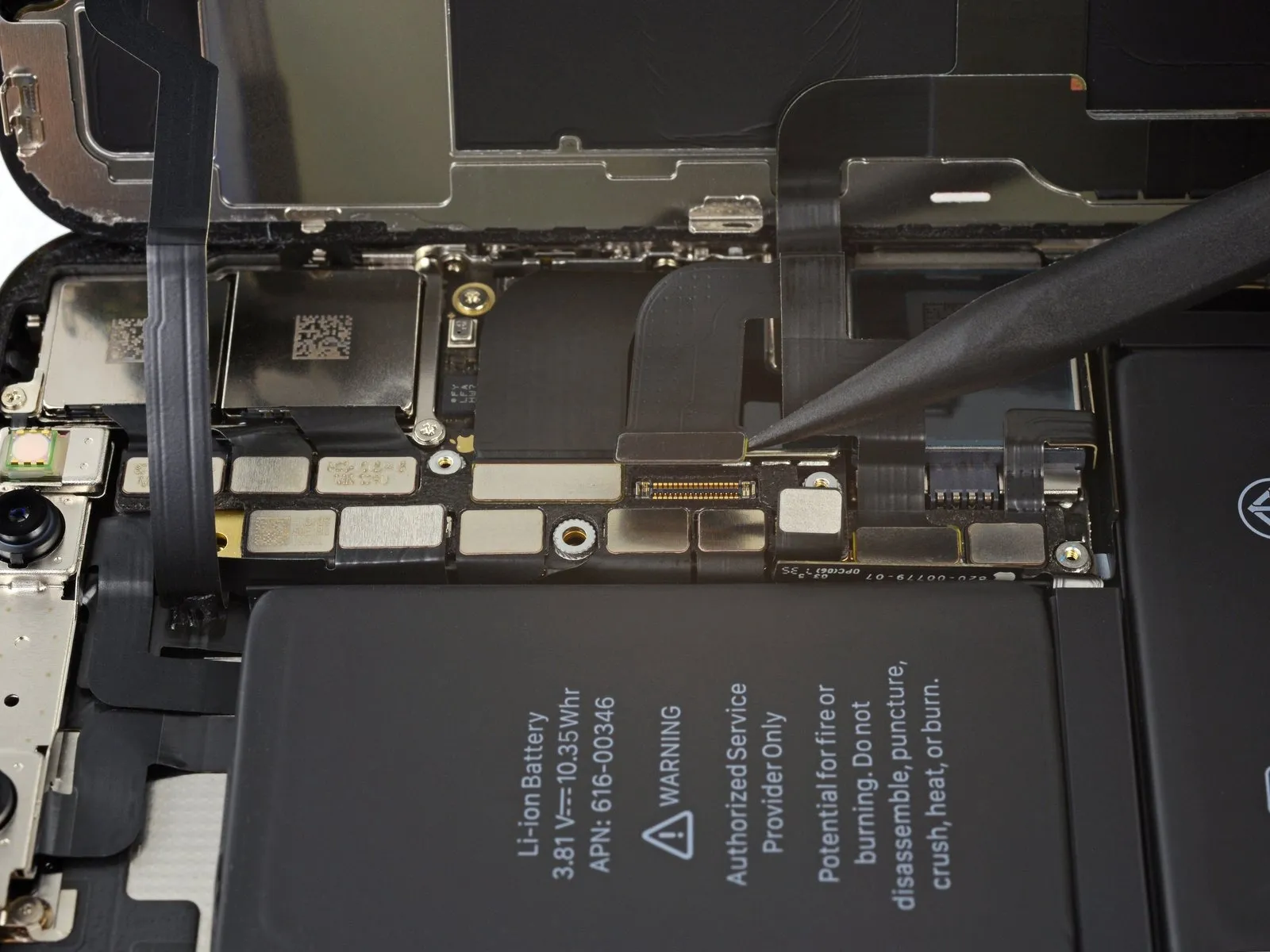
- To proceed with the logic board removal, first, detach the Dock Flex cable connector.
- Carefully flex the cable's form,creating a 90-degree angle,then position it vertically to provide sufficient space for the logic board's extraction.
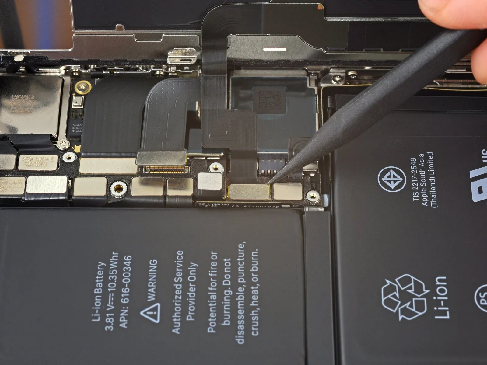
Step 61 | Button / Wireless Charging Connector
Step 62 | Cellular Antenna Connector

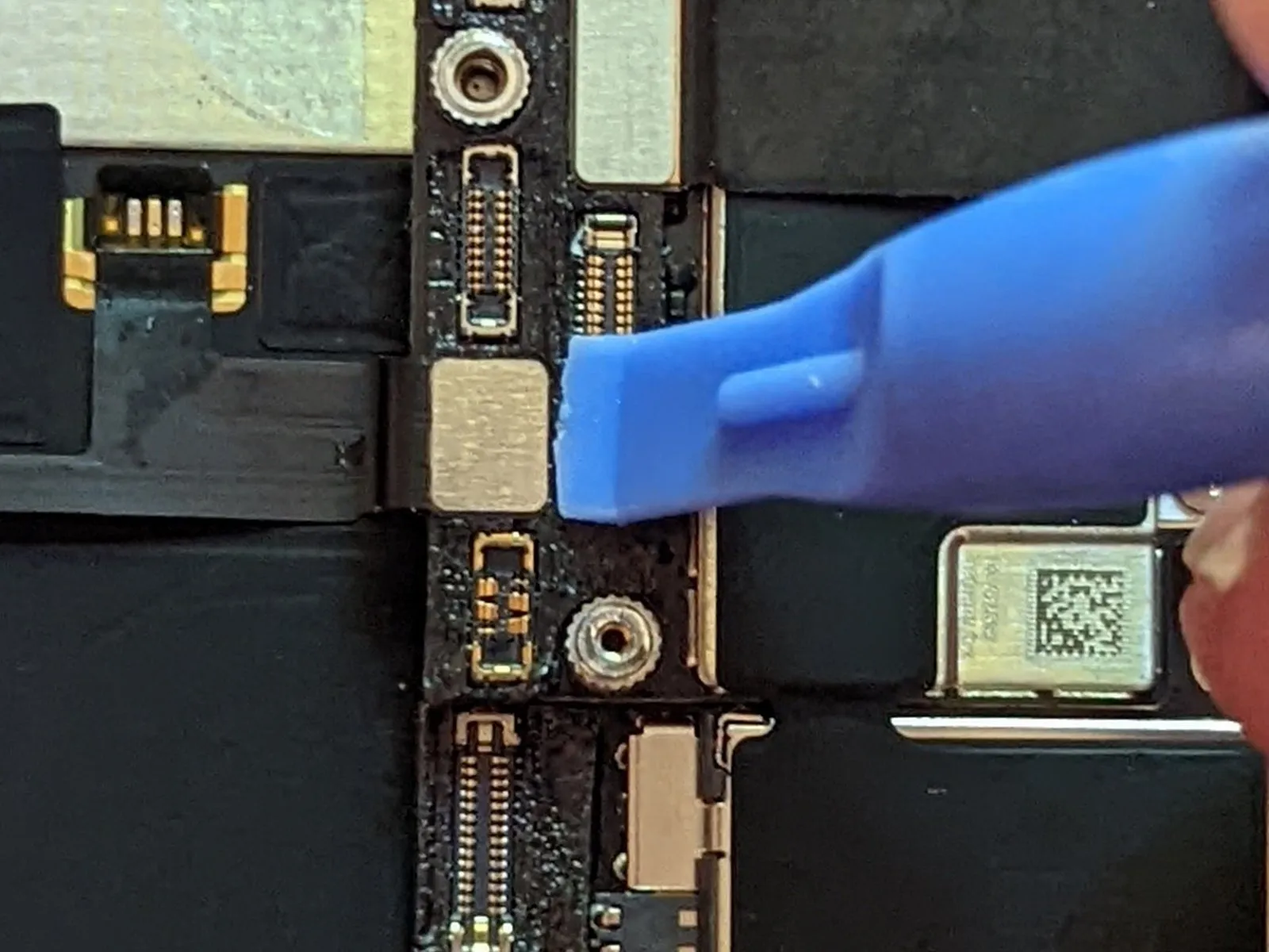
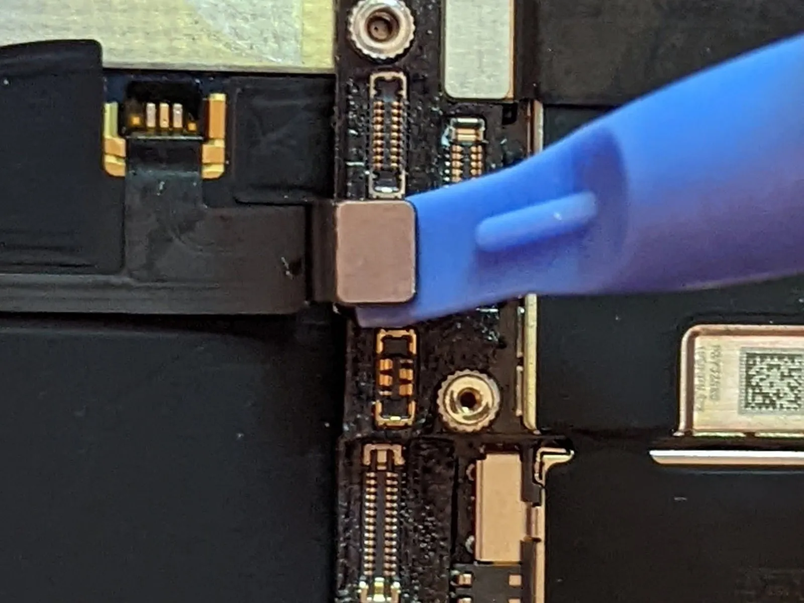
- To proceed with the repair, first detach the connector from the Cellular Antenna cable.
- Carefully deflect the cable's path to ensure it doesn't obstruct subsequent work.
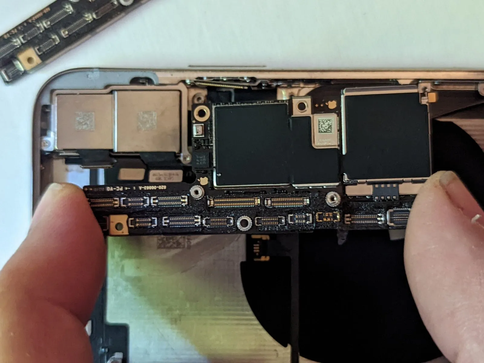
Step 63
Ensure the SIM card tray is extracted before attempting to detach the logic board, as its presence will obstruct removal. Should you have been unable to do so previously, proceed with its extraction at this time.
Detach the two Phillips screws that secure the component.
A single Phillips screw with a 2.7 mm head is required.
A single Phillips screw with a 2.1 mm head is also needed.
Extract the 2.0 mm Phillips screw that provides grounding..
Carefully remove the grounding tab.
It is essential to reinstall the metal grounding tab, maintaining its original position and alignment.
Step 64 | Retract the SIM Eject Pin
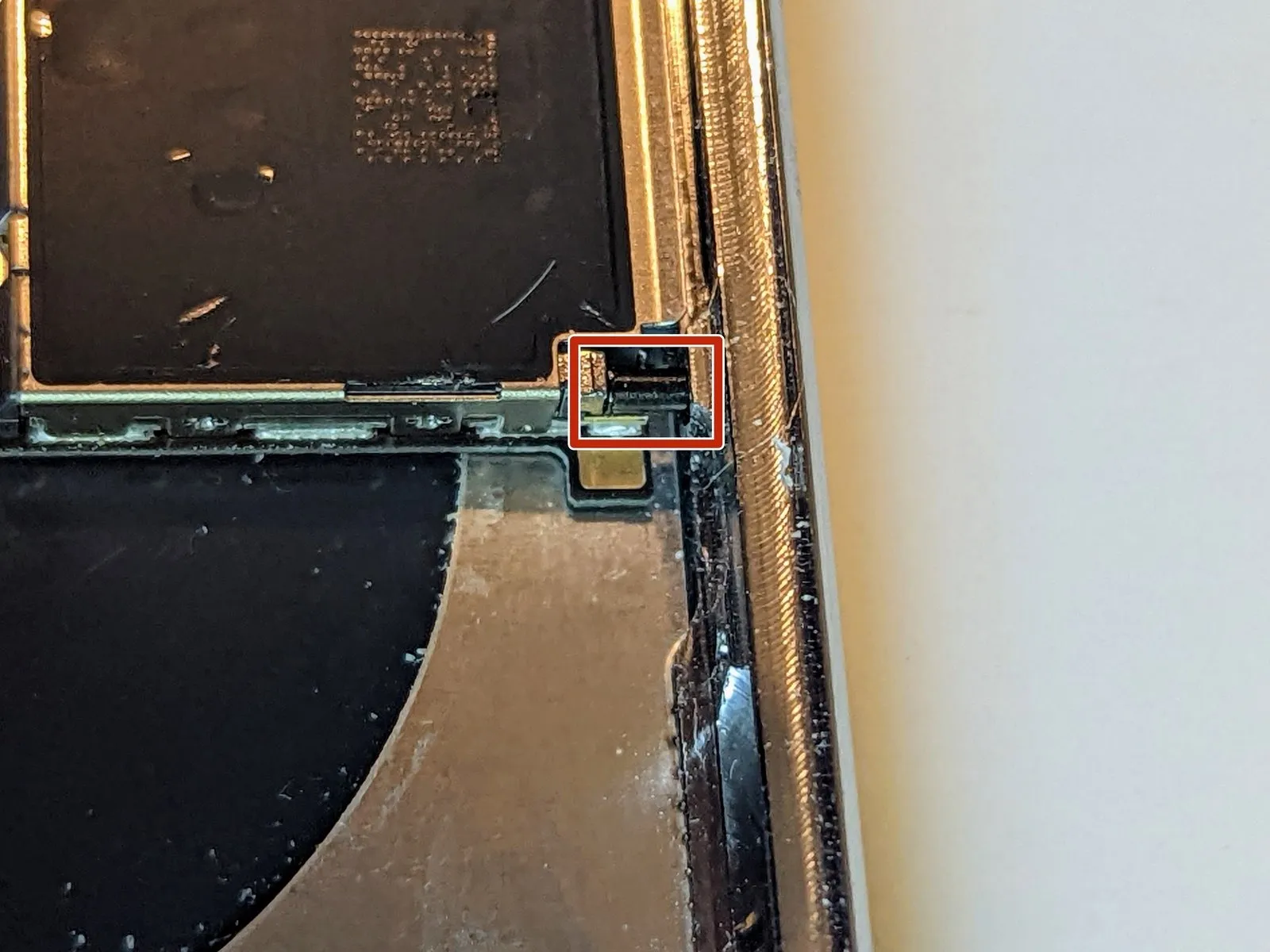
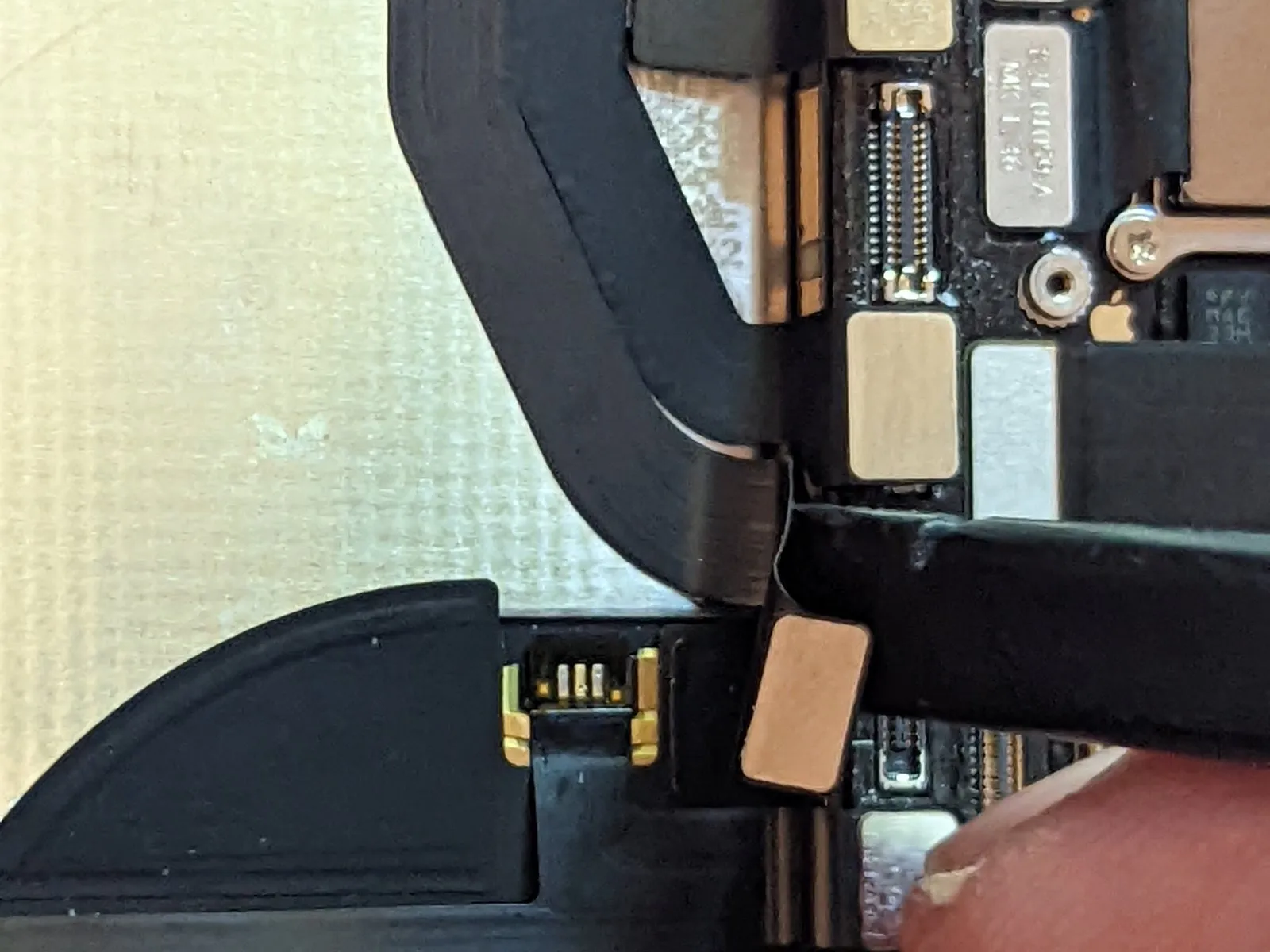
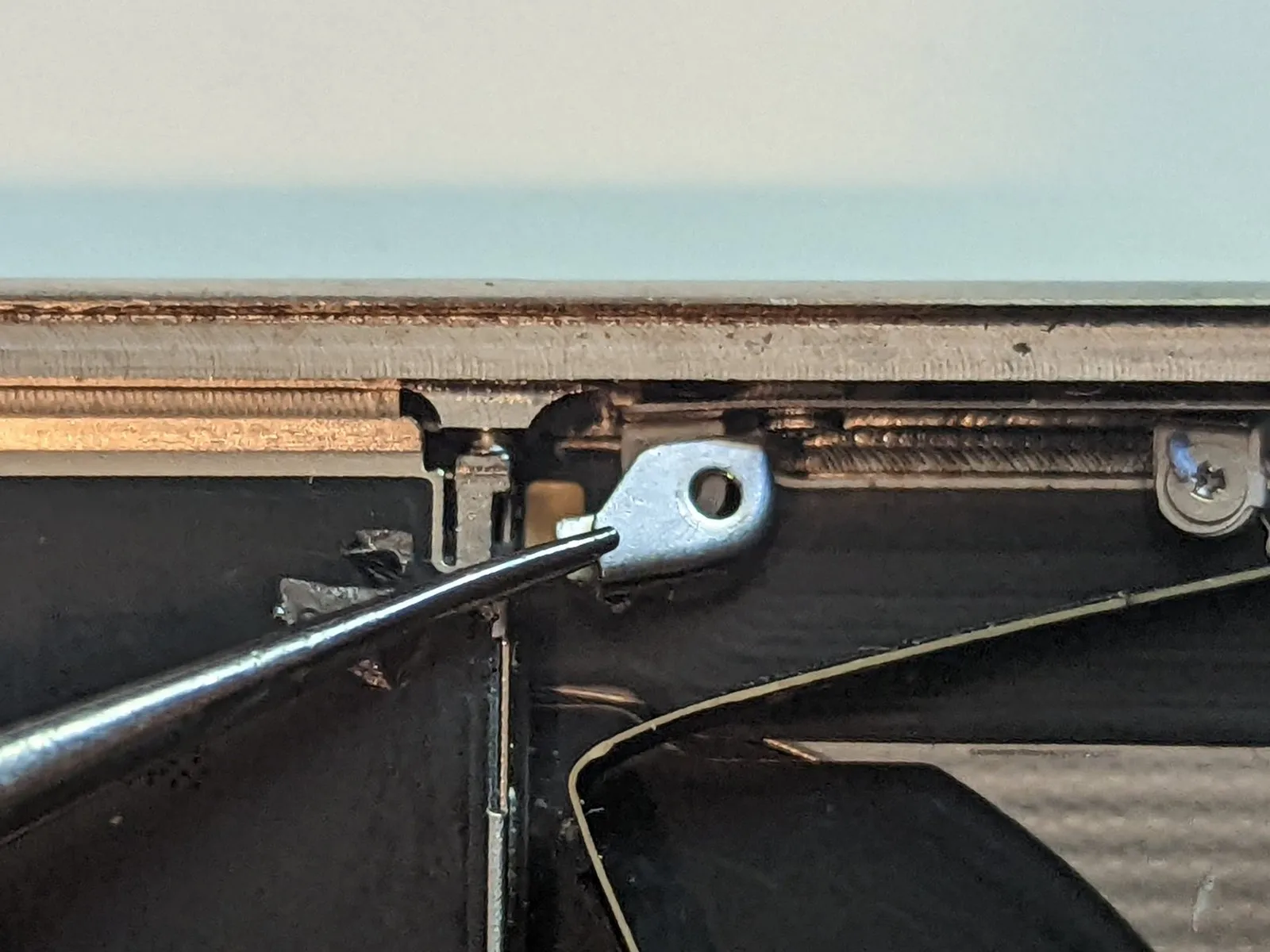
Upon SIM card removal, a retaining pin extends from the device's chassis, engaging the release lever within the SIM card holder. To facilitate logic board disassembly, this pin must be manually retracted back into its housing, preventing obstruction.
Step 65
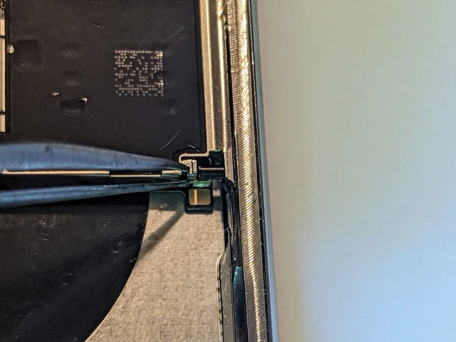


- Employing a set of precision tweezers, carefully maneuver the SIM card ejection lever in a direction parallel to the device's casing.
- The lever's final position will resemble the image provided; this ensures the retaining pin no longer obstructs the logic board's extraction.
Step 66

Step 67 | Volume Button Assembly
- Detach the1.4-millimeter Phillips screwsecuring the grounding tab.
- Extract the grounding tab.
- Pay close attention to the tab's original positioning, ensuring accurate placement when reassembling the device.
Step 68

- To detach the buttons, begin by eliminating the six screws that hold them in place.
- Utilize two Phillips head screwdrivers, each with a 1.5 mm tip..
- Employ two additional Phillips head screwdrivers, these having a 1.9 mm tip size..
- A single Phillips head screwdriver with a 2.4 mm tip is also required..
- Furthermore, a Phillips head screwdriver featuring a 1.7 mm tip will be necessary..
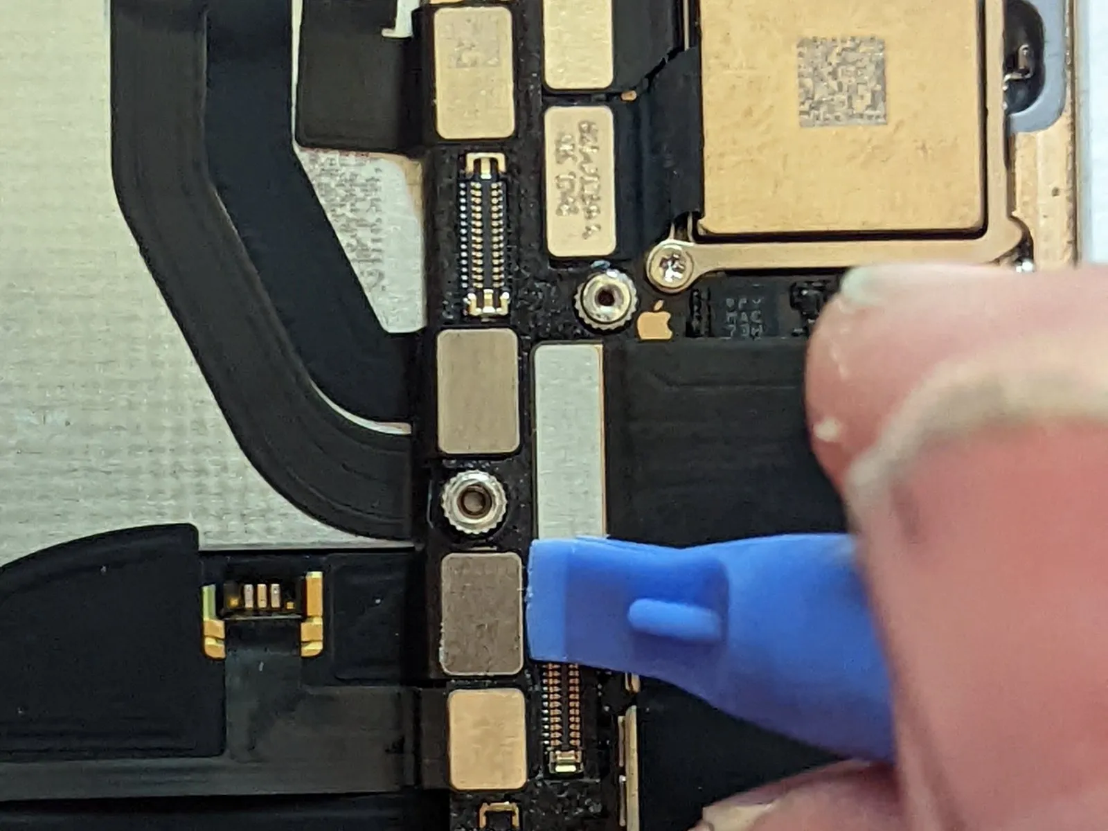
Step 69

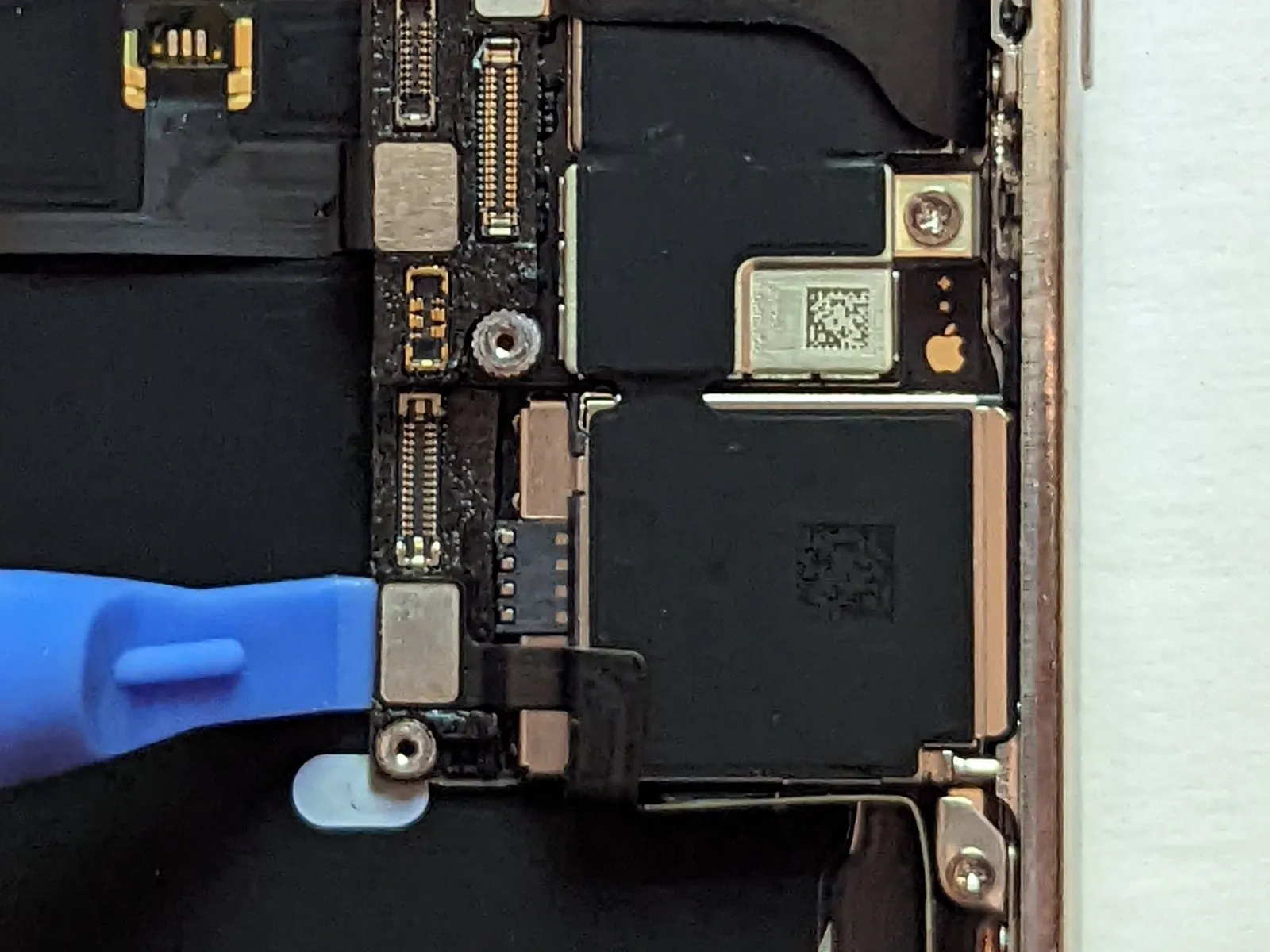
- To deactivate the ringer or silent mode, move the switch located on the device's exterior.
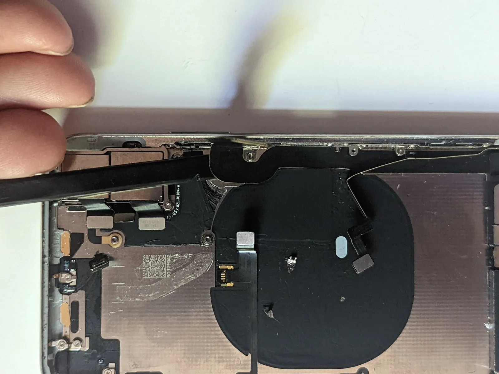
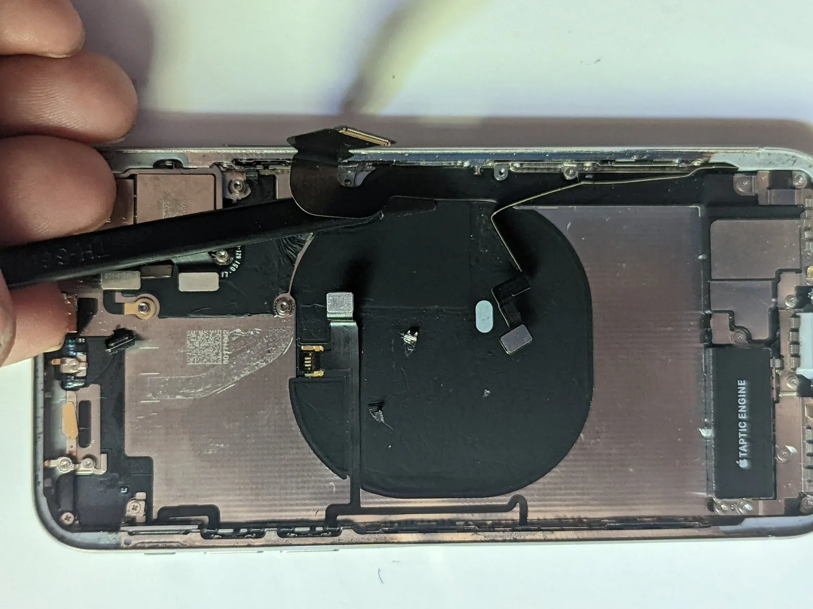
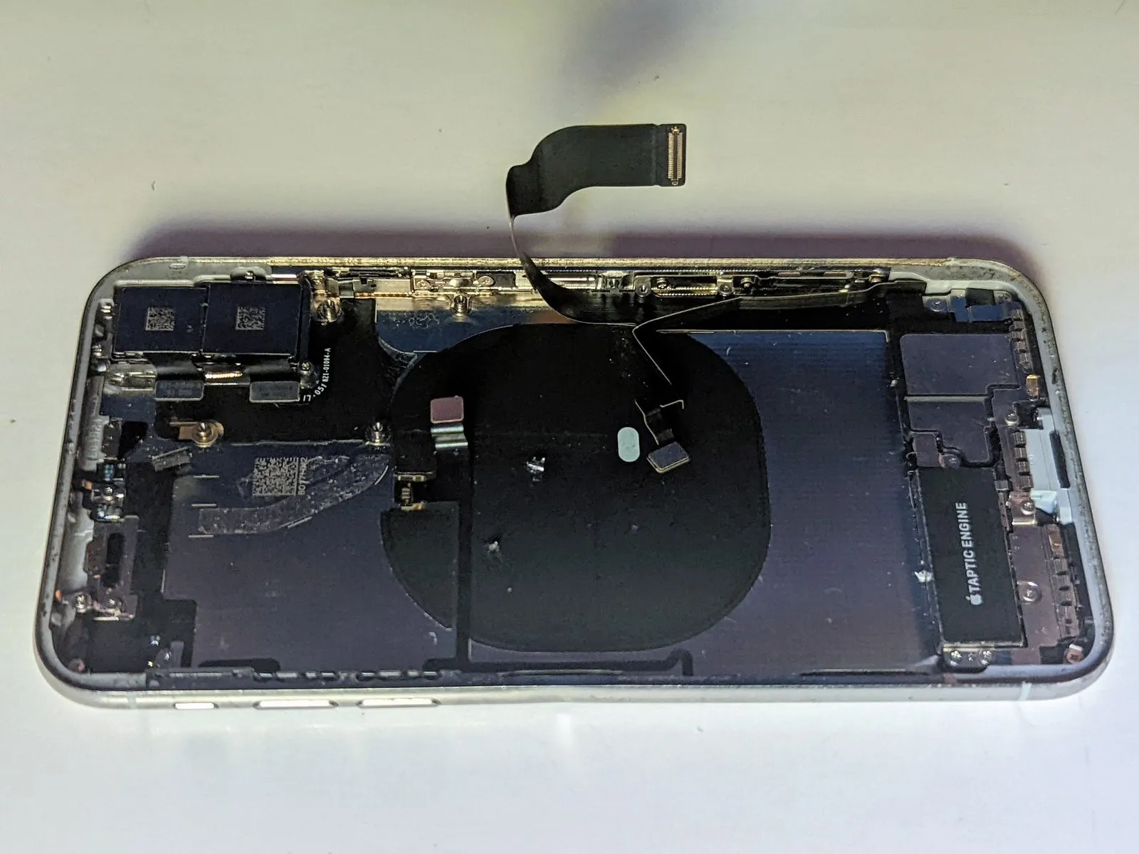
- Employing a specialized plastic pry tool, carefully separate the flexible circuit ribbon cable from the underside of the housing.
Step 70
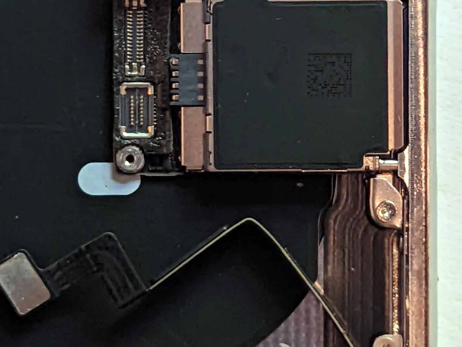
- Applying heat to the device's casing utilizing an iOpener, a hot air gun, or a hair dryer will assist in making the adhesive pliable, facilitating its removal.
- Detach the button cable from its connector.
- Should you intend to reinstall the button/charging coil assembly, exercise exceptional caution during this cable's removal process; its delicate nature and minimal thickness render it exceptionally fragile, necessitating a slow, deliberate approach to minimize stress and potential damage.
- Secure the cable with tweezers while employing a spudger to lift and slide between the cable and the device's housing.
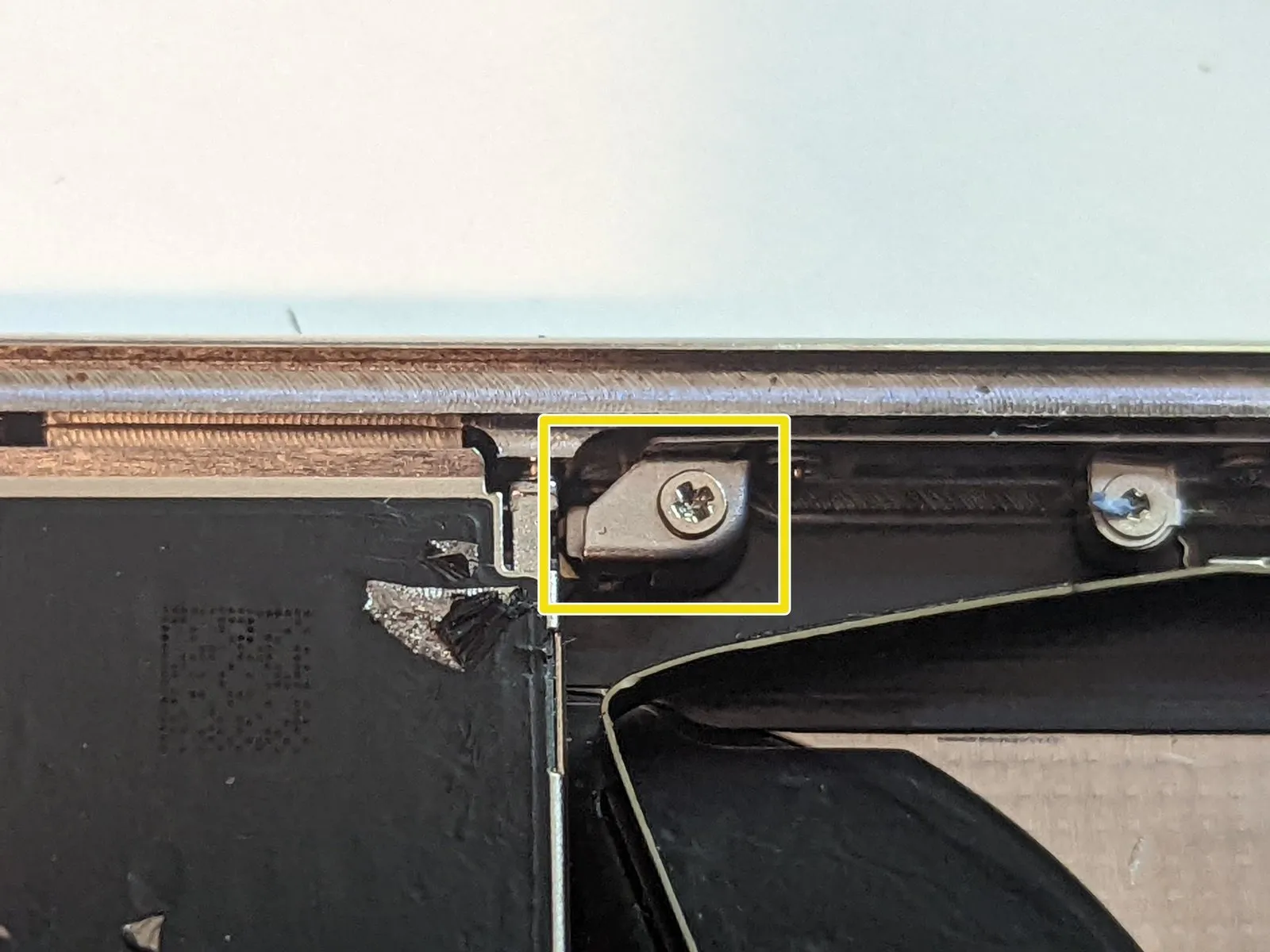
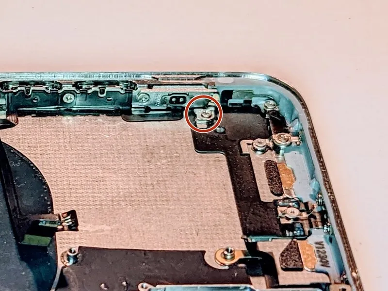
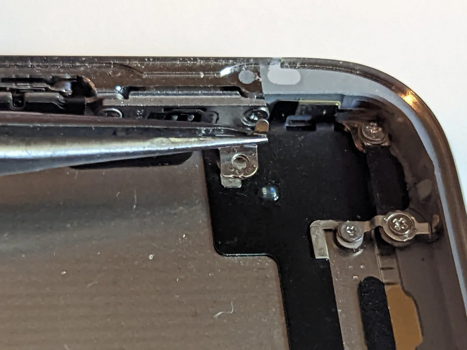
Step 71 | Upper Right Screen Retainer
- To gain access to the power button and screen securing components, carefully lift the terminal end of the dock connector.
- To prevent interference, maneuver the dock connector upwards and away from the work area.
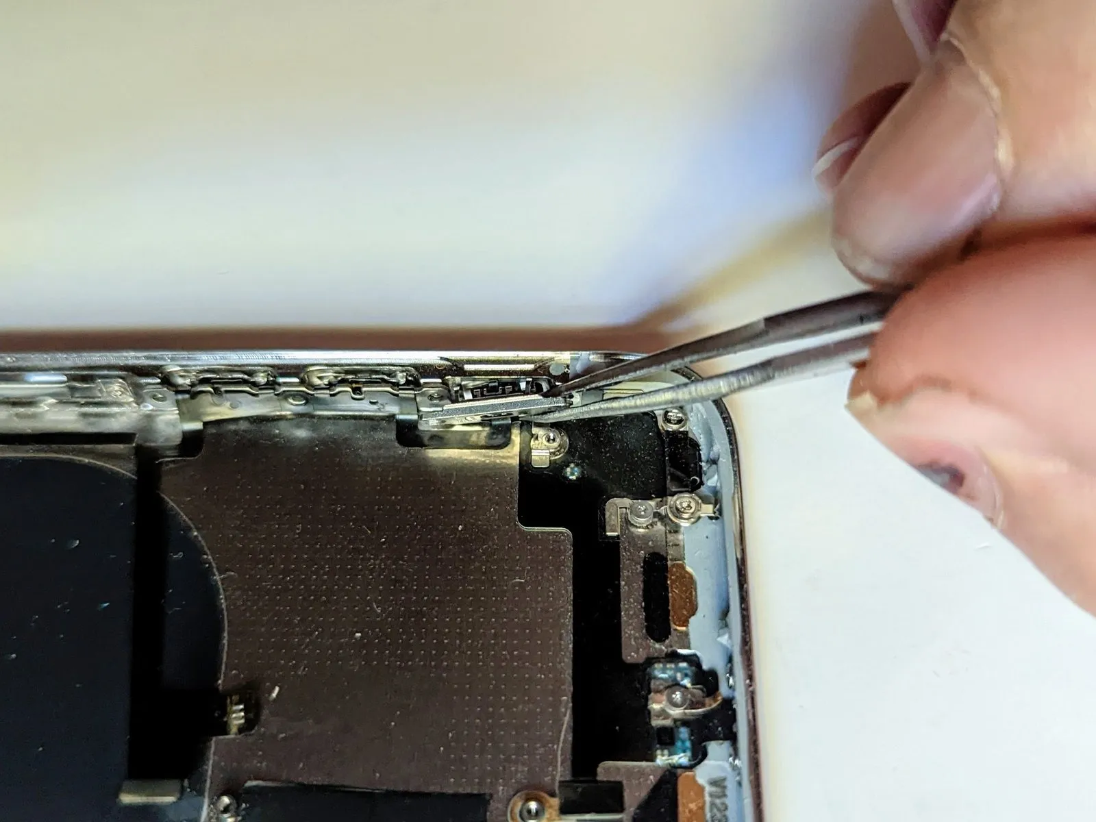
Step 72
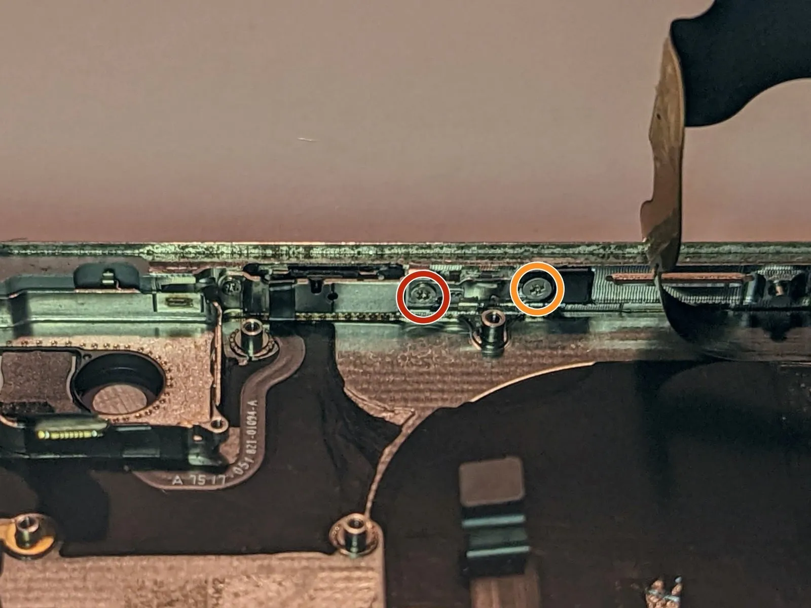
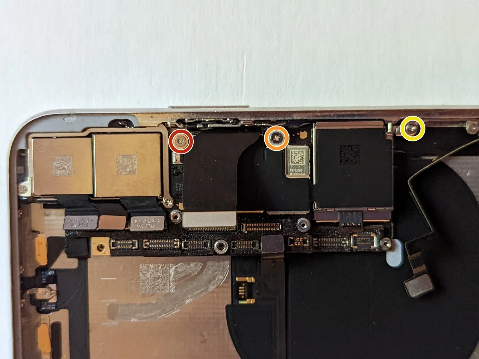
- To detach the screen securing clip, first eliminate the two screws that fasten it in place.
- A 2.1 millimeter Phillips head screwdriver is required for this step..
- A 1.9 millimeter Phillips head screwdriver is also needed..
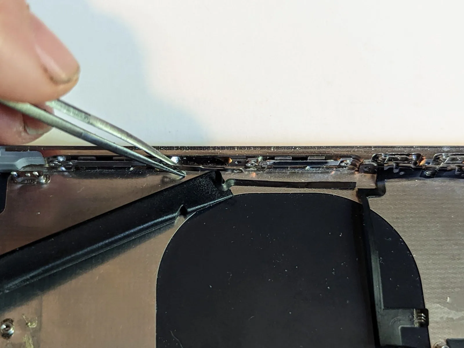
- Carefully disengage the screen retainer from its position.
- During reassembly, ensure the retainer is positioned correctly by sliding it behind the black plastic component located on the end furthest from the power button.
Step 73 | Power Button and Flash Cable
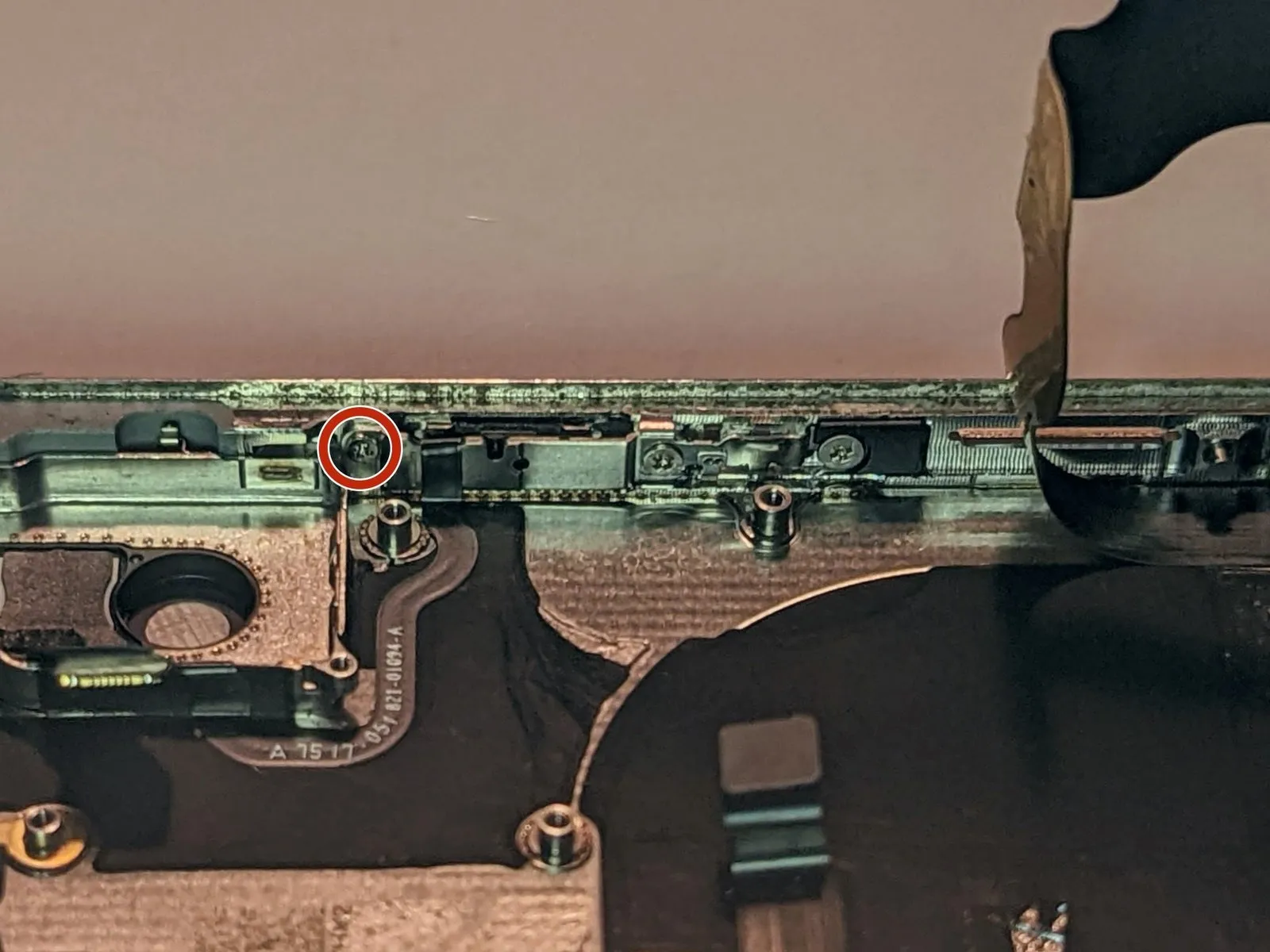
To proceed, detach the final 2.0 mm Phillips screw which is holding the power button in place.
Step 74
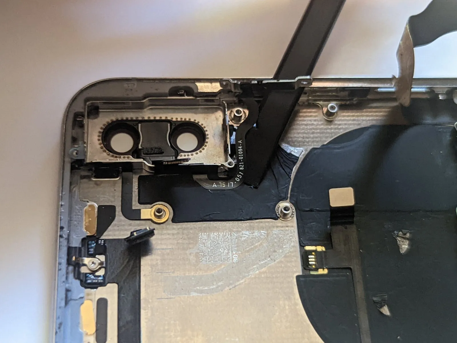
Carefully detach the flexible cable assembly from the chassis.
Step 75
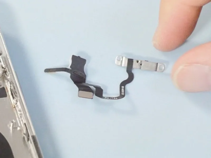

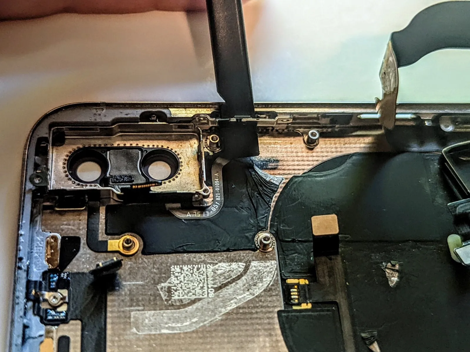
- Utilizing a spudger, disengage the flash and microphone components.
- Subsequently, detach the entire assembly.
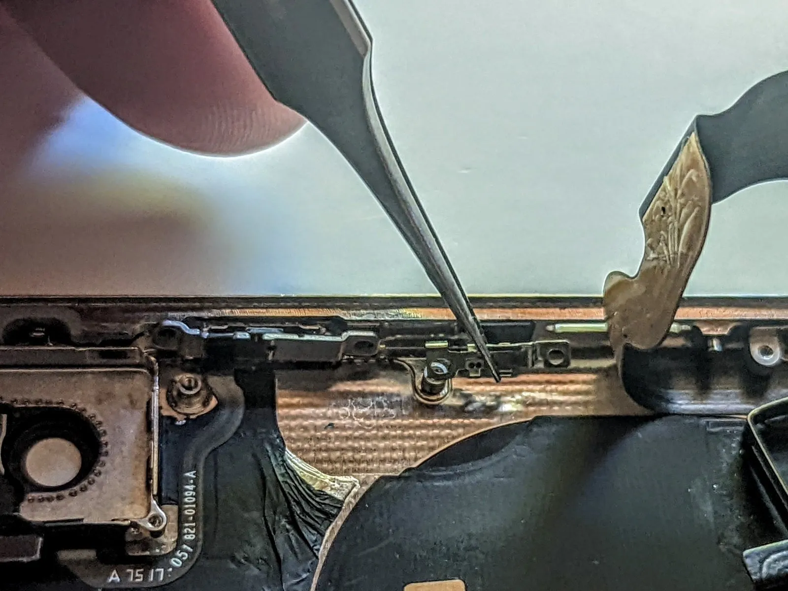
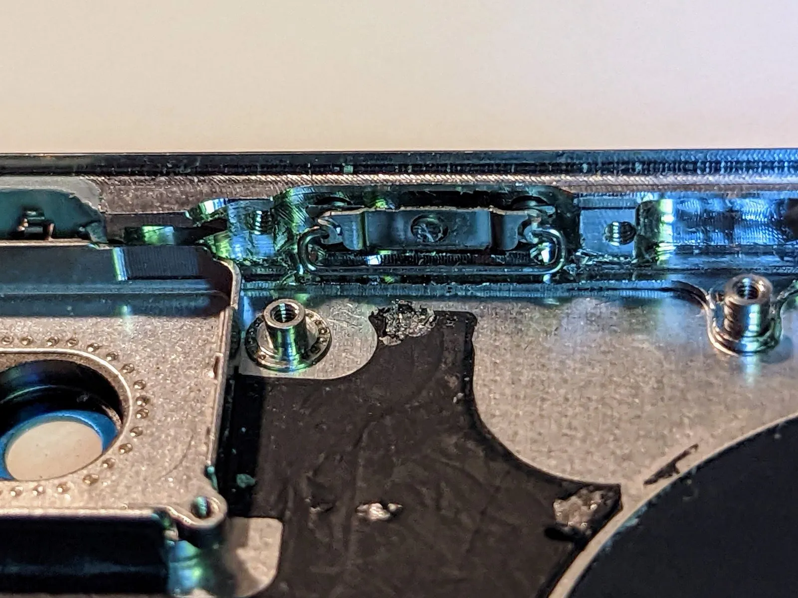
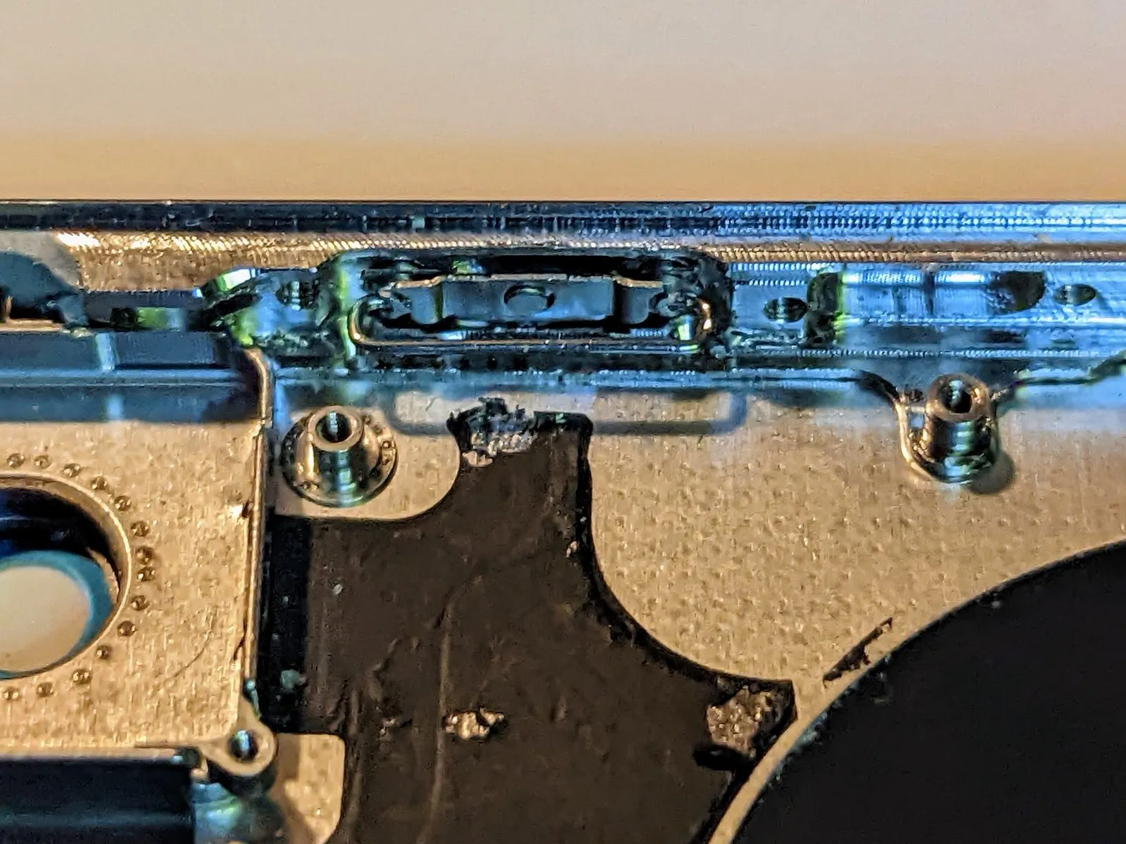
Step 76 | Remove the Ring/Silent Switch
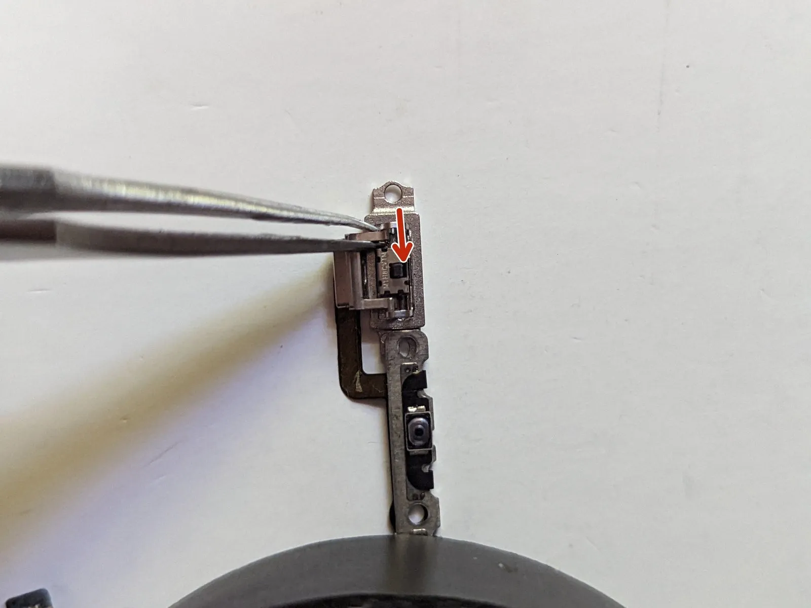
- Move the switch's activation lever to the leftward position.
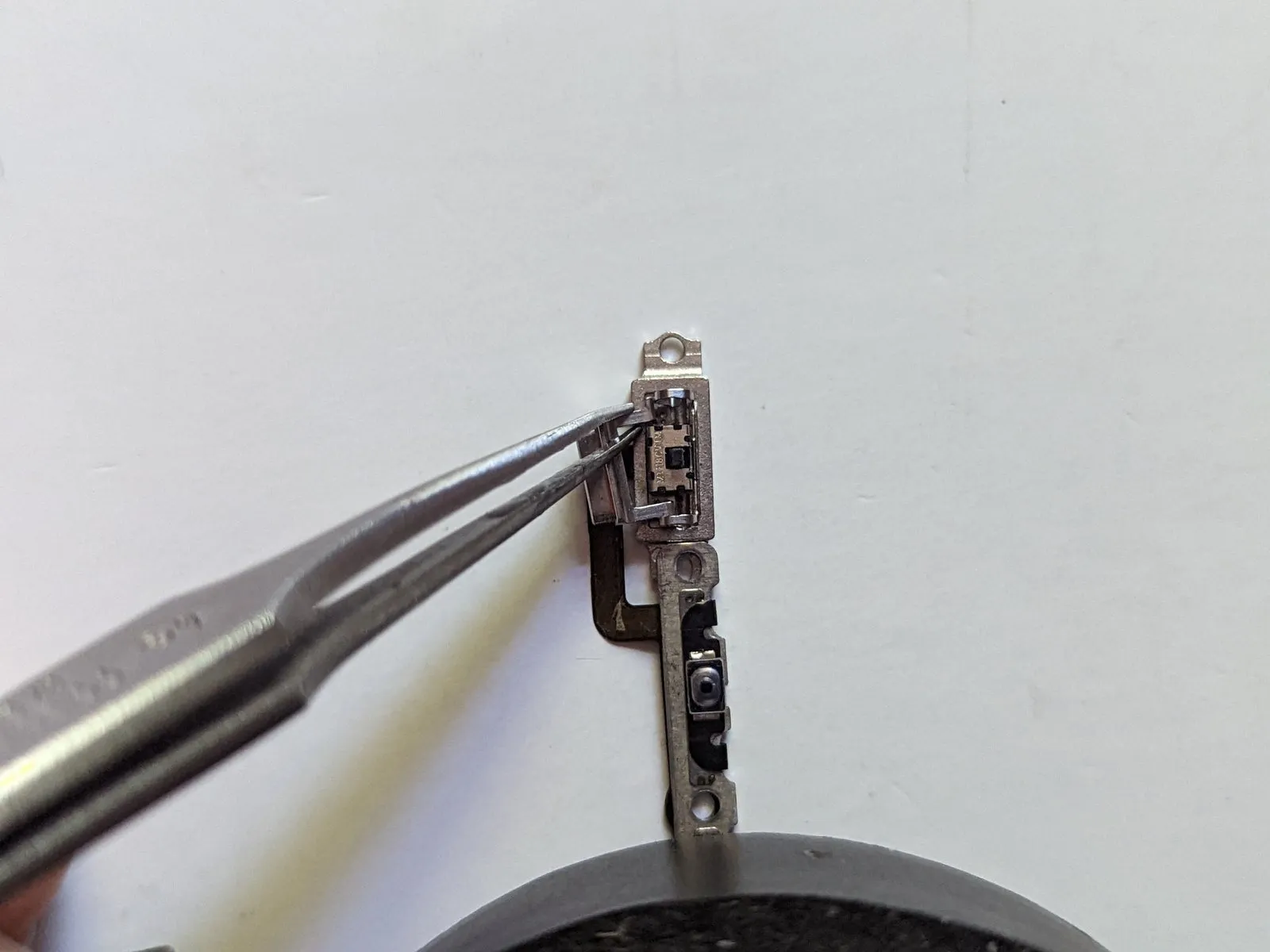
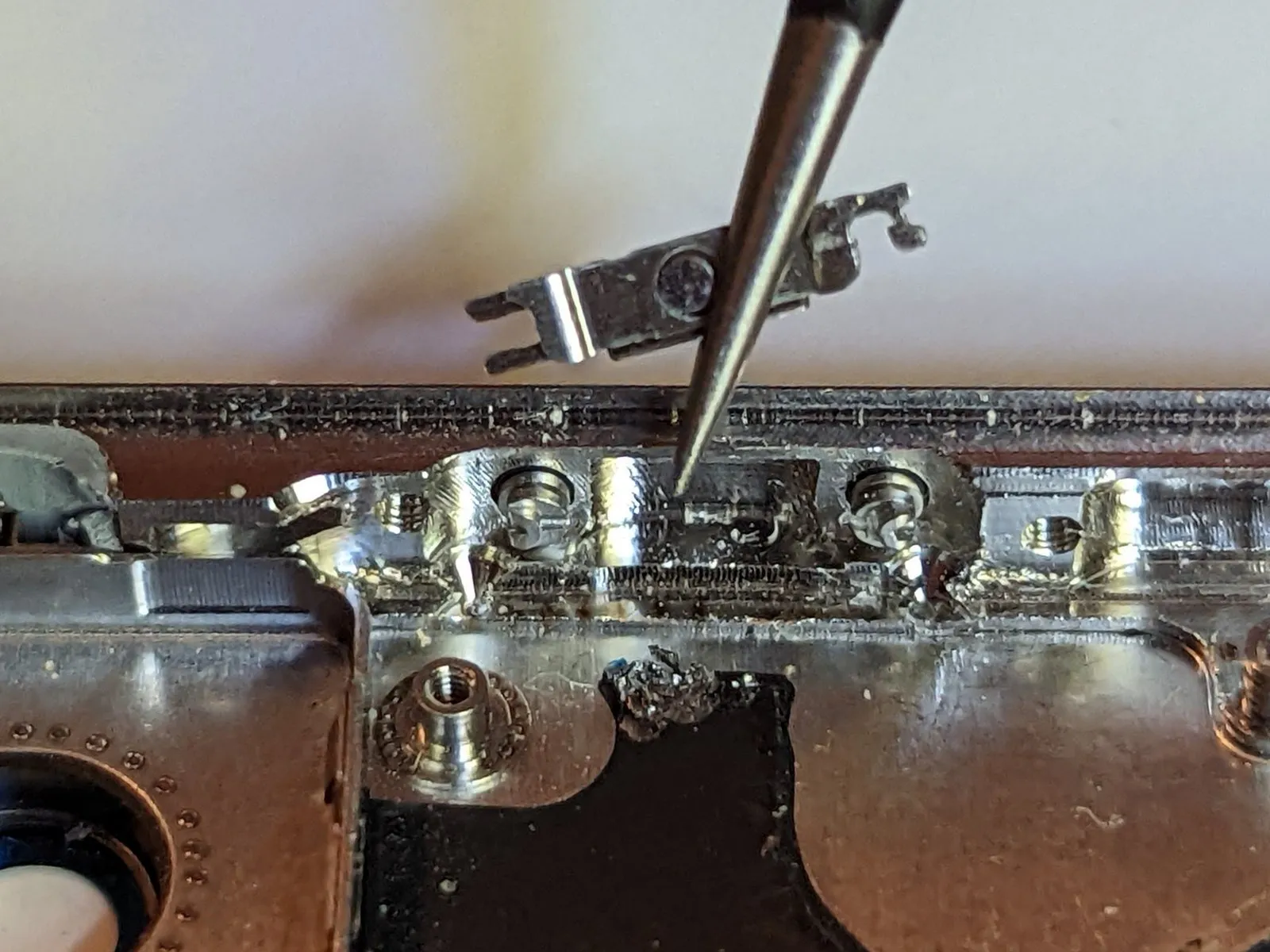
- Utilize fine-tipped tweezers to carefully hold the switch's upper arm, then move it downwards to disengage the retaining mechanism.
Elevate the component's distal end and advance it outward from the opposite side. - During reinstallation, ensure the orange marking aligns with the uppermost surface, as demonstrated in the accompanying visual reference.
Step 77 | Remove the Button Spring Clips
Prior to commencing disassembly, it is essential to review the instructional video referenced in the initial section. Disconnecting these buttons presents a significant challenge and can be quite irritating; therefore, meticulously observe the video and endeavor to replicate iPhoneRepairGirl's procedures with precision.
- Raise the retaining clip to a 90-degree angle.
Step 78


- Utilize tweezers to securely hold one extremity of the spring clip.
- Exert a steady force on the clip's end to disengage it from the button's mechanism.
- Slightly pivot the clip away from the button's surface.
- Move the clip in the reverse direction to release the remaining end.
- Detach the spring clip completely.
- Perform these steps again for both the volume increase and volume decrease buttons.
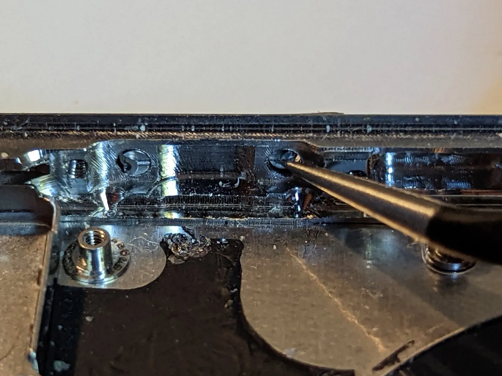
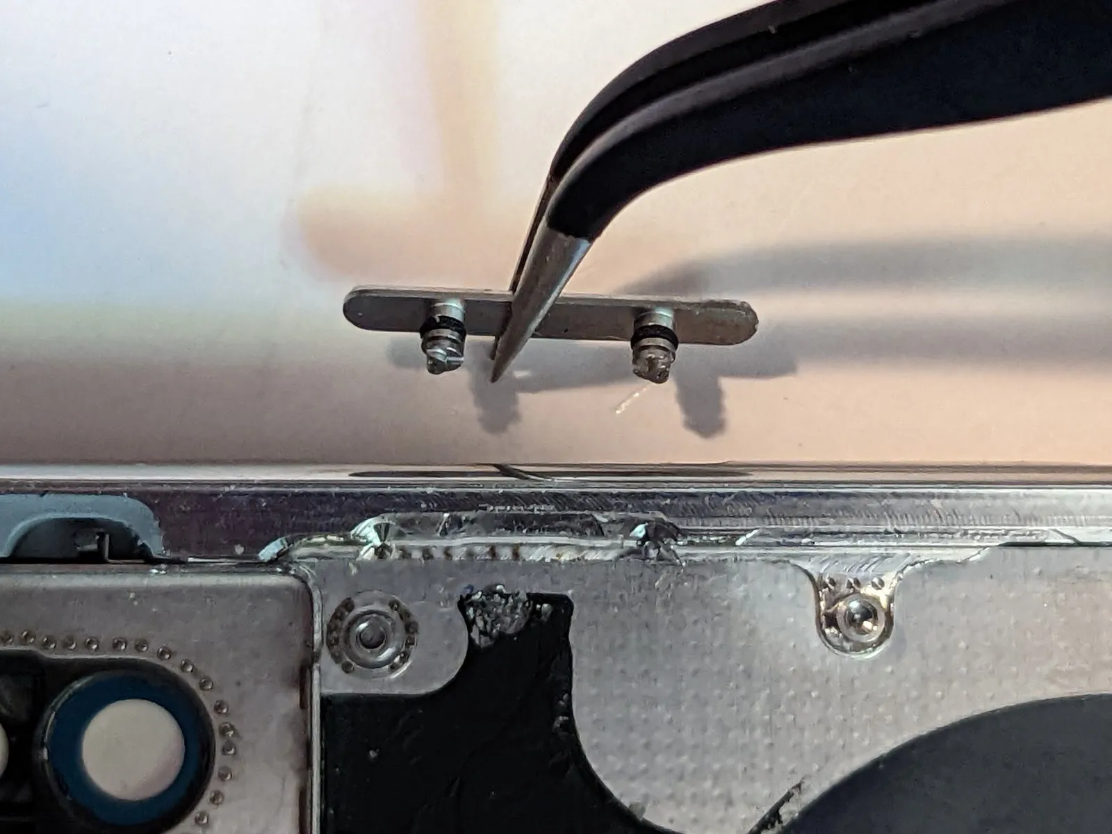
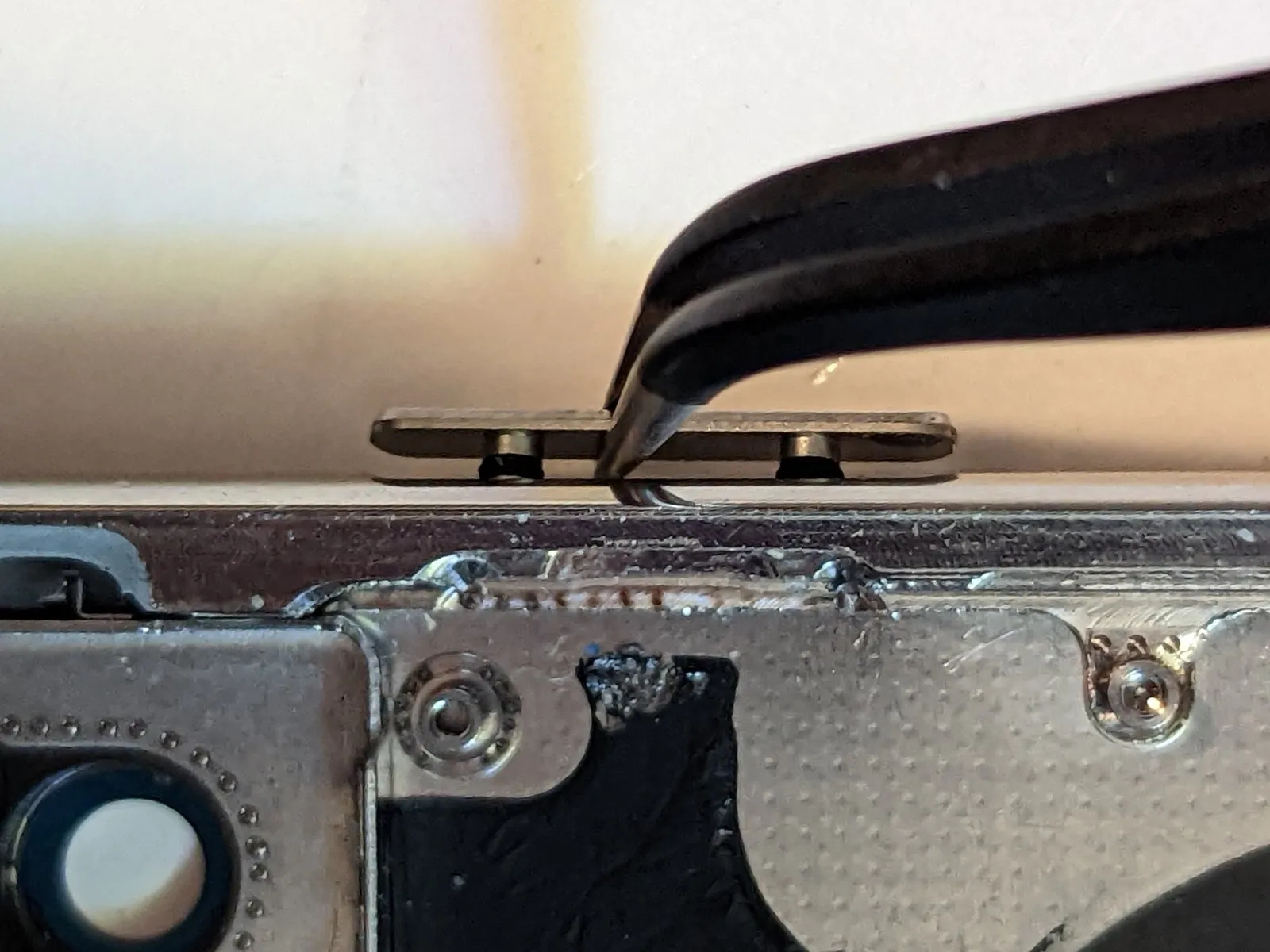
Step 79 | Remove the Button Retaining Plate


Using a prying tool, elevate the right portion of the retaining clip approximately 20 degrees.20 degrees.
- To disengage the retainer, draw it directly outward, away from the button's surface.
During reassembly, ensure the retainer is fully seated; a consistent, even space should exist along the entire bottom edge of the button.
Step 80 | Remove the Volume and Power Buttons
Should external access to the button prove impossible, utilize a tool to extract the retaining pins from within the device's interior.
- Detach the button assembly.
Prior to commencing reassembly, review the instructional video; the reassembly process presents a greater challenge than disassembly. Exercise considerable patience and meticulous technique, as proper alignment is essential for successful button reinstallation.