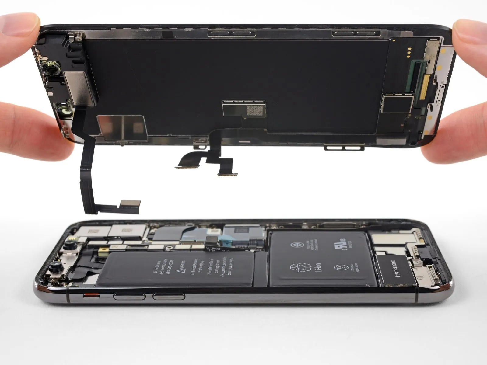
iPhone X Rear Case Replacement
Follow these instructions to disassemble all parts from the back cover of your device.Apple iPhone XTo enable replacement of a damaged cover—whether cracked, dented, or bent—this procedure details the steps for detaching the speaker, associated cables, the taptic engine, the battery, the logic board, and the button covers.
Due to the complexity involved, this particular procedure represents the highest level of difficulty for repairs on this device.Apple iPhone XAvoid any procedures requiring microscopic soldering techniques.
Step 1 | SIM Card


- Carefully position aUse the provided SIM card removal tool to release the SIM card tray.Use a paperclip to gently depress the small hole situated on the iPhone’s edge, close to the side button, which releases the SIM card tray.
- Apply consistent, moderate force to release the tray.
Step 2
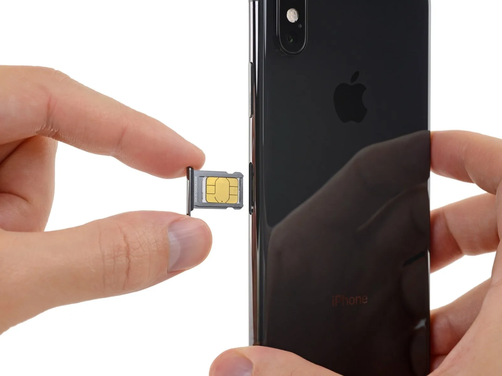

- Using a SIM ejection tool or a straightened paperclip, depress the release mechanism located on the side of the iPhone to extract the SIM card tray.
- Due to the tray's design, the SIM card can be ejected with minimal force.
- Verify the SIM card's alignment with the tray before sliding it back in.
- To safeguard internal components from water and dust, the SIM tray is sealed with a slender rubber gasket; if this gasket is compromised or absent, either substitute the gasket itself or replace the SIM tray assembly.
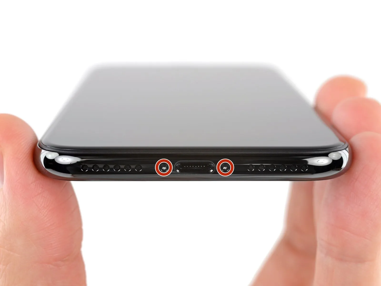
Step 3 | Pentalobe Screws
To start, ensure the iPhone's battery is depleted to less than 25% capacity; a fully charged lithium-ion battery presents a fire and/or explosion hazard if damaged.
To prevent electrical shock or damage, ensure the iPhone is completely de-energized prior to starting the repair process.
Using a Phillips head screwdriver, detach the two screws.Screws with a 6.9 mm length and a pentalobe head are required.Along the lower perimeter of the iPhone.
- Damaged or stripped screws must be replaced with new ones.
Removing the display assembly will damage the iPhone's water resistance; ensure you have replacement seals available for installation before continuing, or exercise extreme caution to prevent liquid ingress if reinstalling the display without new seals.
Step 4 | Mark your opening picks


To avoid potential damage to your device, ensure the opening pick does not extend beyond a safe depth; use this procedure to identify the maximum allowable insertion point on the pick.
Determine the dimension using an appropriate measuring tool.Three millimeters.Using a permanent marker, clearly indicate the opening point on the pick.
Alternatively, use markings to indicate various lengths on the remaining corners of the pick.
To achieve a similar effect, affix a coin to the pick's tip, positioning it precisely 3 millimeters from the end.
Step 5 | Tape over any cracks


- To minimize additional damage and protect yourself from injury while servicing a cracked iPhone screen, apply tape across the affected glass area.
Apply strips of transparent packing tape across the iPhone screen, ensuring complete coverage of the display surface with overlapping sections. - To safeguard your eyes from potential glass fragments released during the repair process, always use safety glasses.
- Should the suction cup fail to adhere during the subsequent procedures, create a handle by folding a durable tape—like duct tape—and use this to raise the screen.
- As a last resort, apply a small amount of superglue to secure the suction cup directly to the screen.
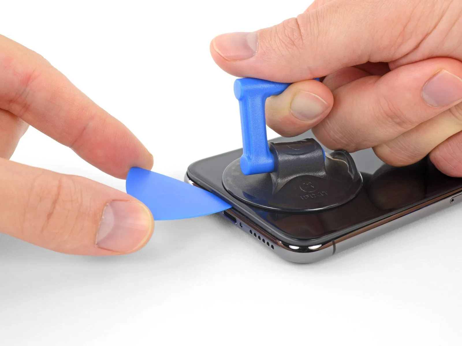
Step 6 | Anti-Clamp instructions


Refer to the included guide for detailed procedures regarding the Anti-Clamp’s operation.
- To release the Anti-Clamp's arms, move the blue handle in a rearward direction.
- Position the arms so they clear the left or right side of the iPhone, then move them into place.
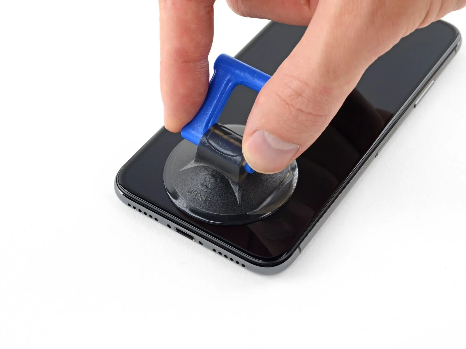
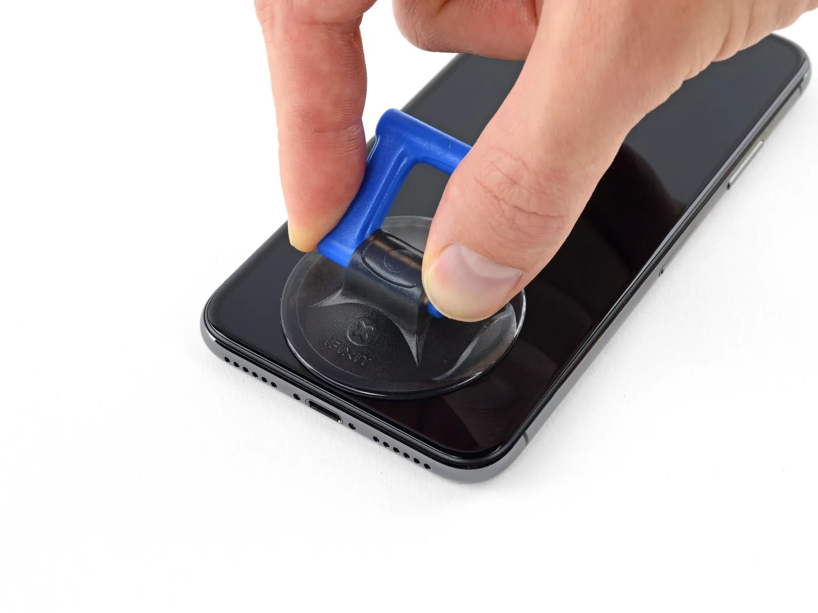
- Secure the iPhone by placing a suction cup close to the lower front edge and another near the lower rear edge.
- Apply vacuum by pressing the cups firmly against the surface needing treatment.
- To improve the Anti-Clamp's grip on your iPhone if the factory finish feels too slick, apply adhesive tape to the device's exterior.
Step 7


Rotate the handle fully, completing a 360-degree turn, observing for the initial signs of cup expansion.
Maintain parallel positioning of the suction cups; should misalignment occur, gently reduce the suction and reposition the arms.
Step 8


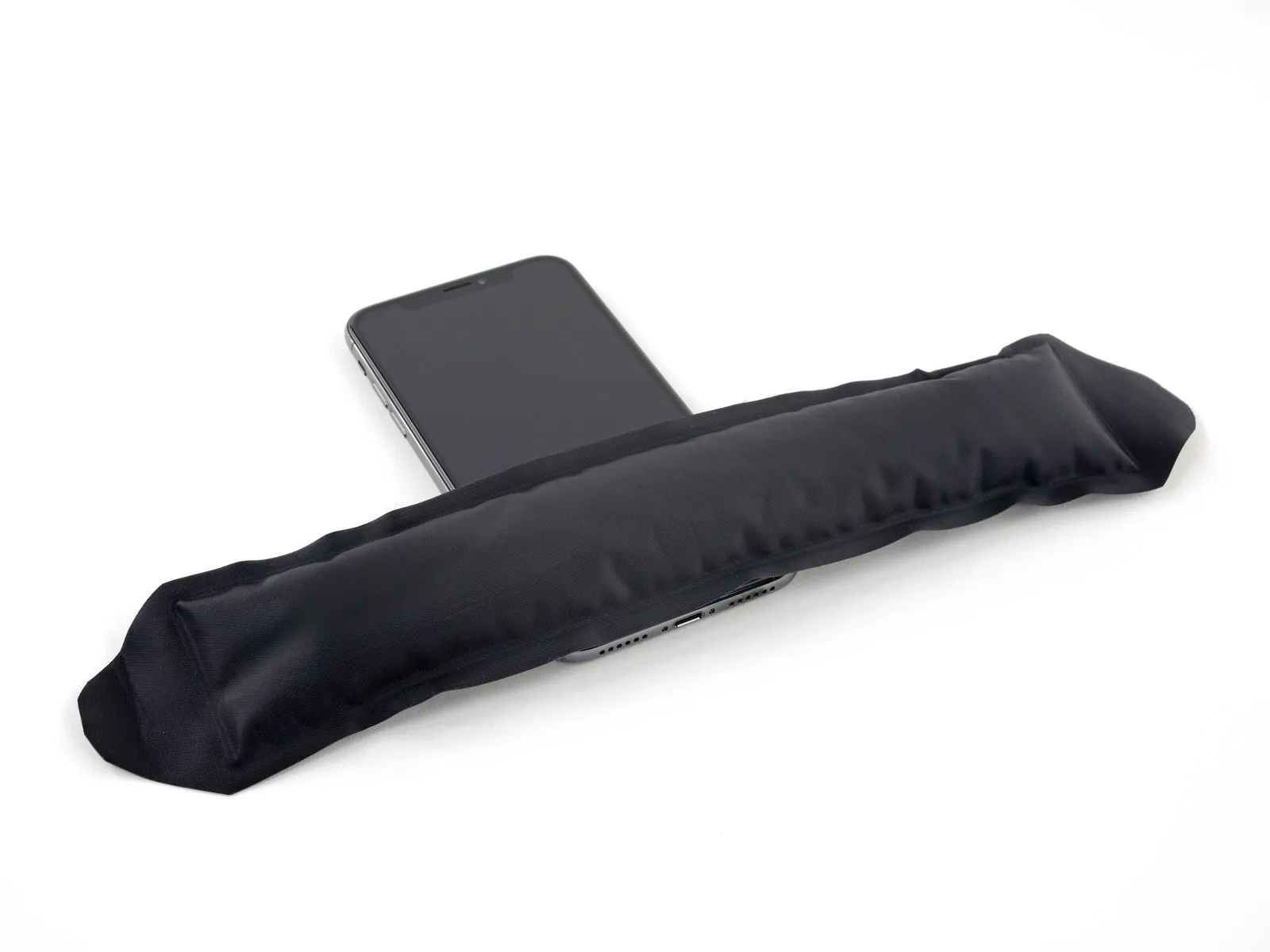
Employing a hair dryer, heat gun, or hot plate is an alternative, but exercise caution as excessive heat may compromise the display or internal battery.
- Position the iOpener flat against the iPhone's lower edge.
- Allow a full 60 seconds for the adhesive to soften, creating a separation.
- Using a specialized opening tool, gently slide it between the display panel and the surrounding plastic trim, ensuring the tool does not contact the screen surface.
- To ensure adequate separation, increase the heat applied to the component and then rotate the handle 90 degrees.
- Allow the Anti-Clamp device to function for a full minute after each incremental adjustment, limiting each adjustment to a maximum of 90 degrees.
Step 9
- To loosen the adhesive securing the iPhone's lower edge, apply heat using a hairdryer, heat gun, or iOpener for roughly one minute.
- Excessive heat from a hairdryer or heat gun can harm the screen; therefore, use caution and avoid overheating.
Step 10
Step 11
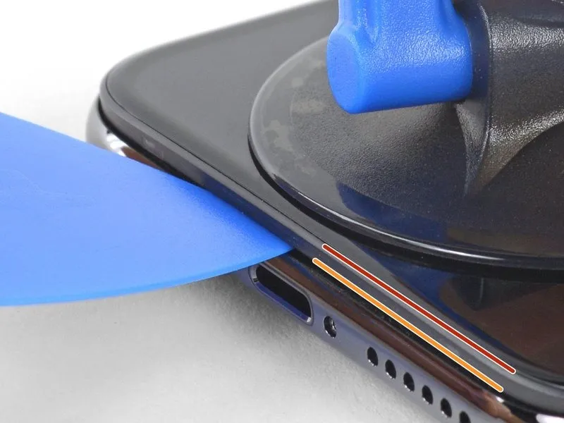
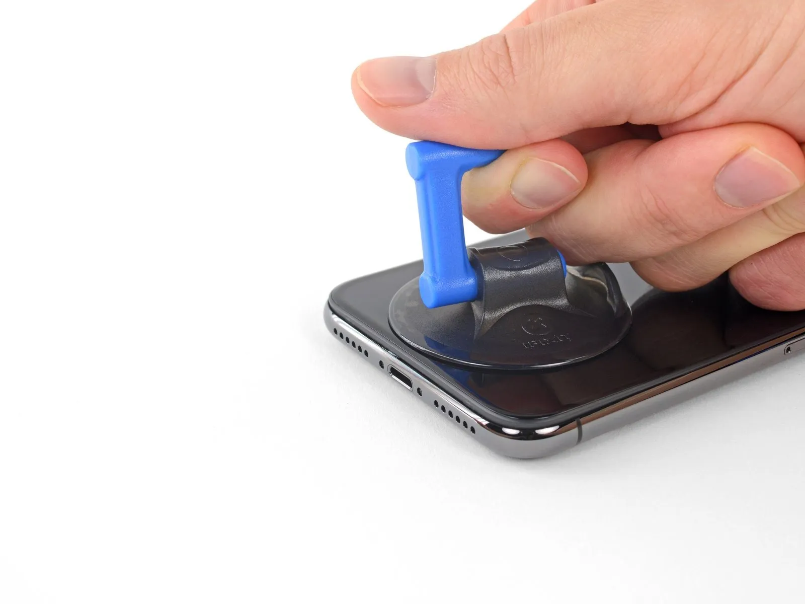
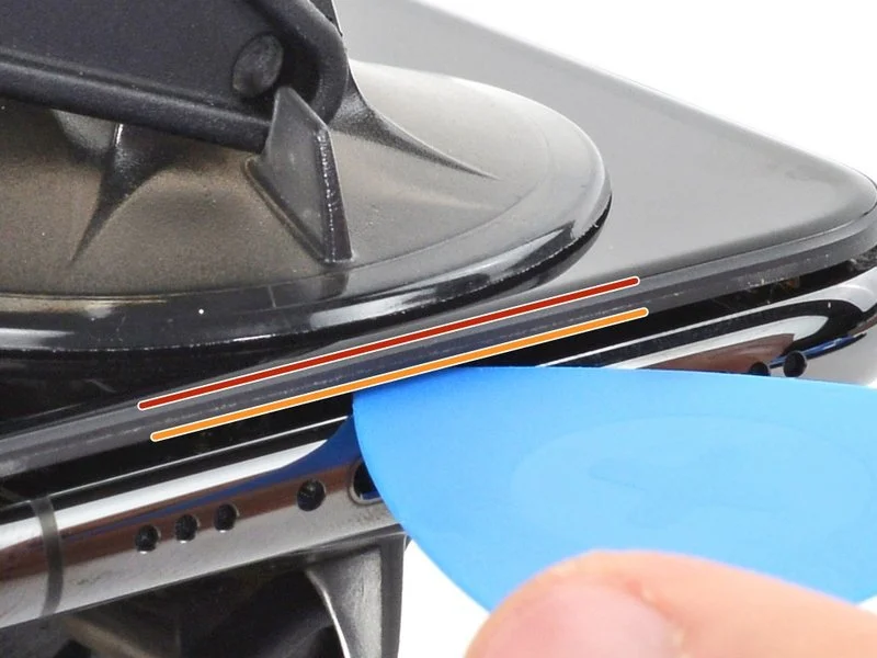
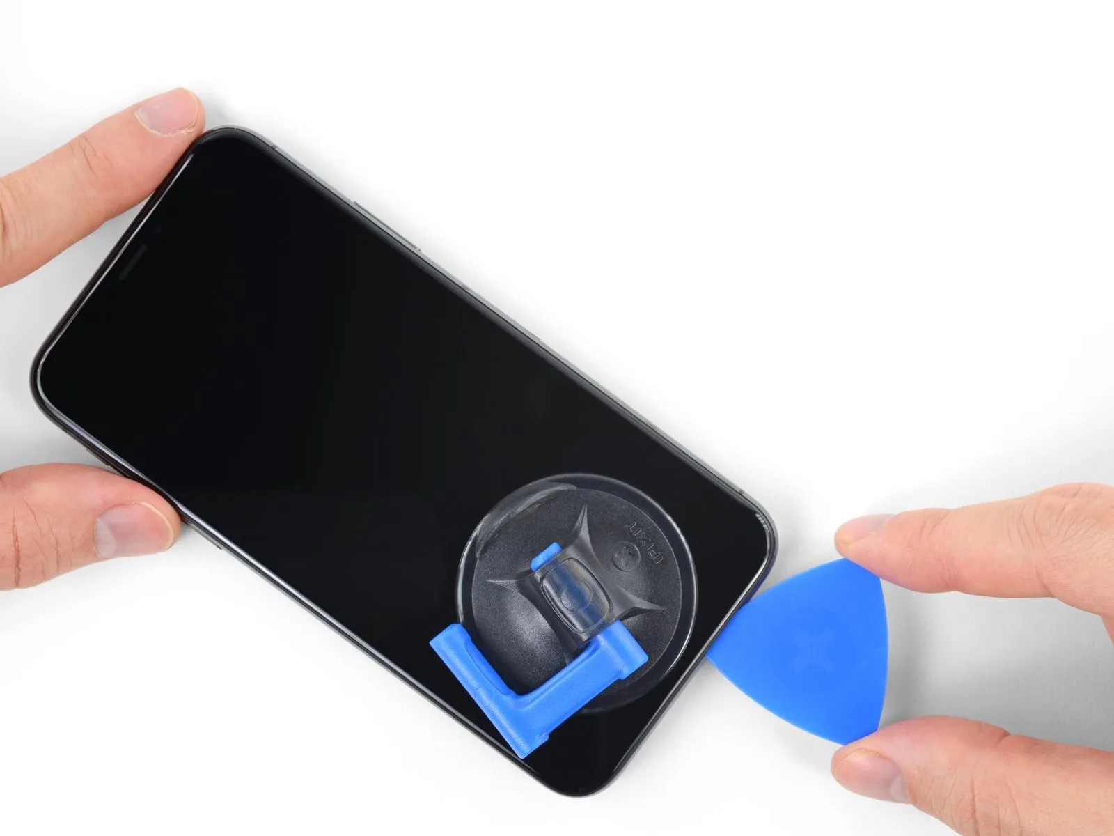
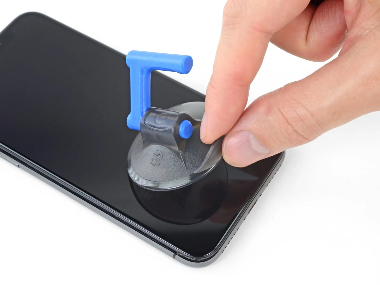
- Apply steady, even force to lift the suction cup, generating a small separation between the screen assembly and the device's frame.
- Using a specialized opening tool, gently pry apart the plastic frame surrounding the display, being careful to avoid contact with the screen's surface.
- Due to the robust nature of the watertight adhesive securing the screen, considerable force is required to initially separate it. Should you encounter difficulty, apply additional heat and gently oscillate the screen in a vertical motion to soften the adhesive, facilitating the creation of a gap sufficient for tool insertion.
Step 12
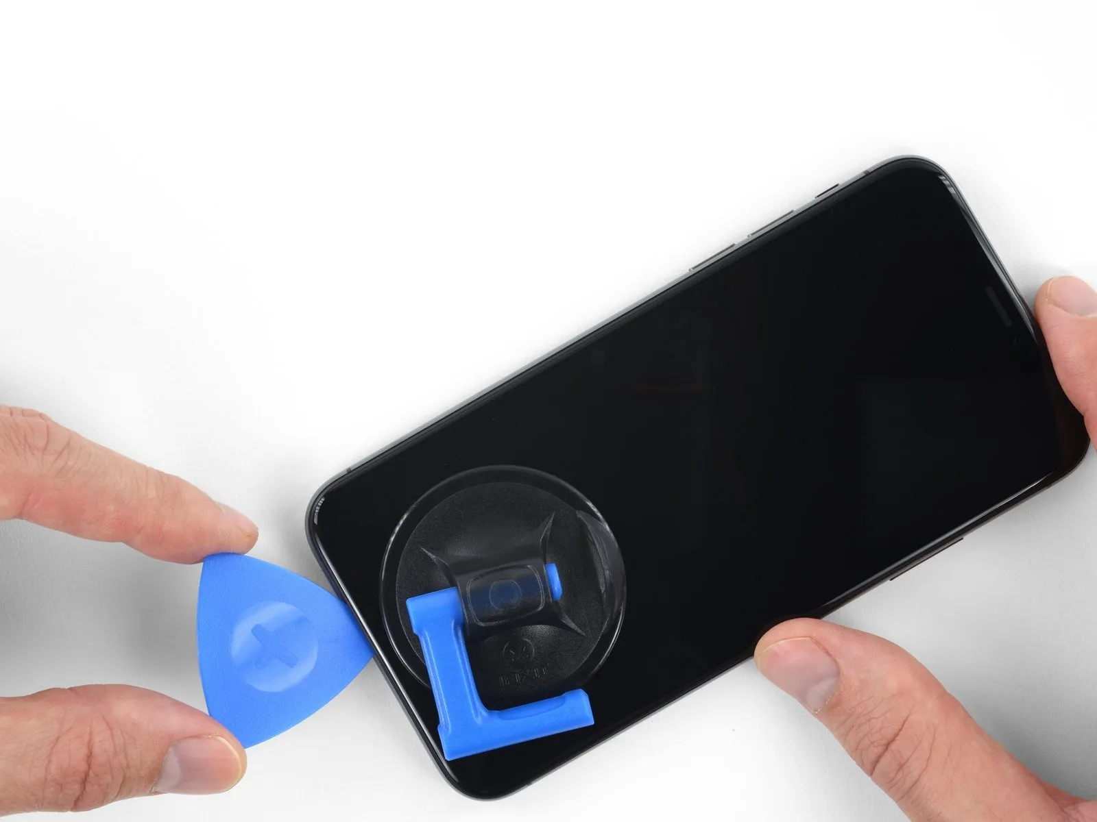
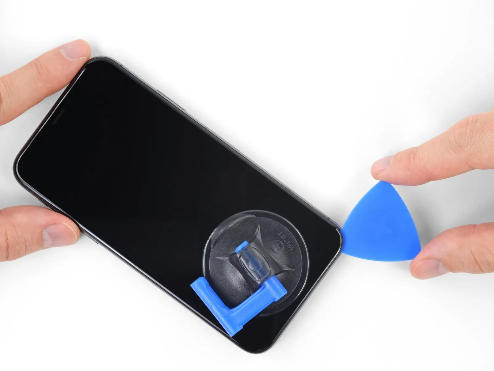
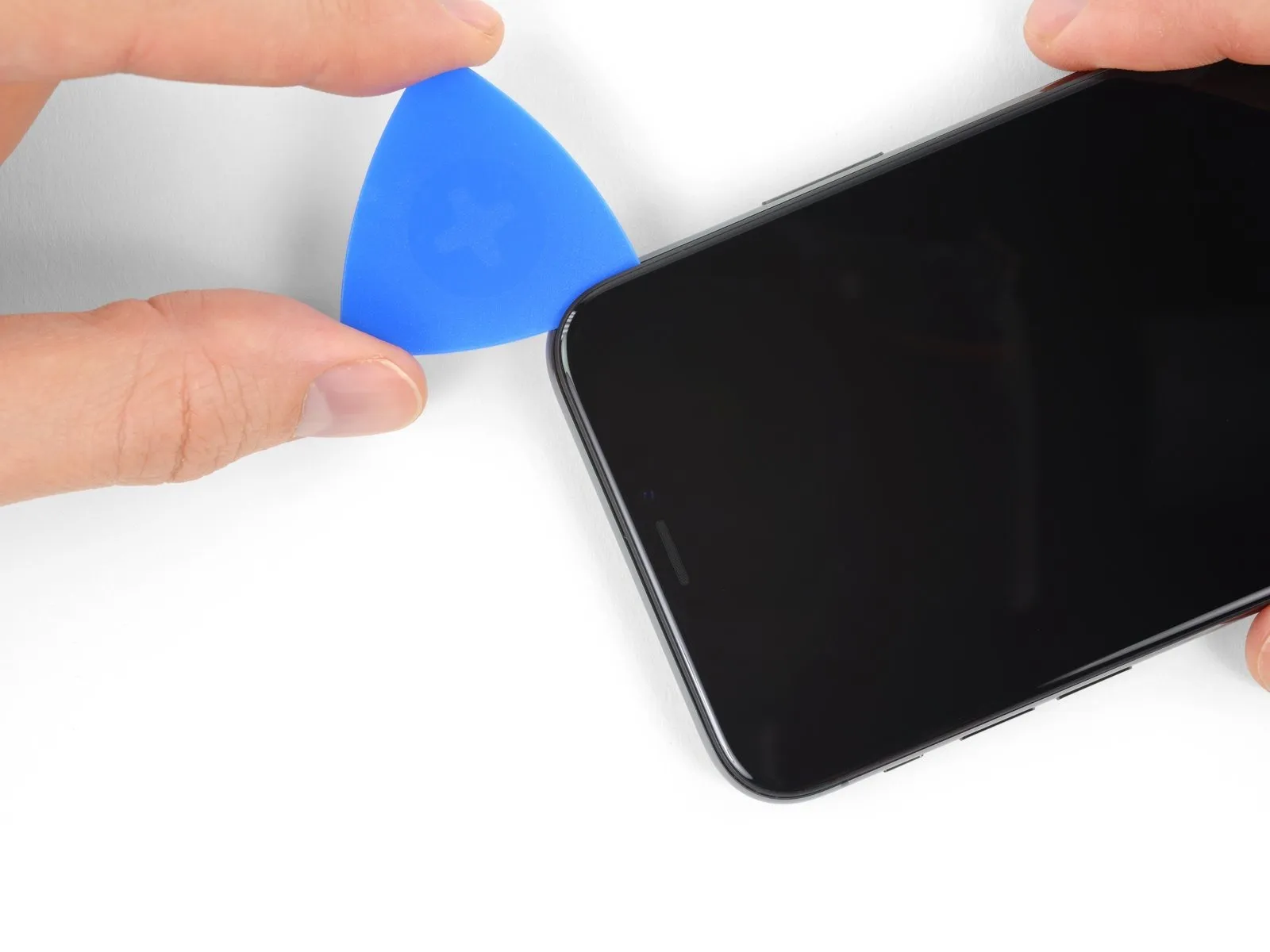
- Using the opening pick, carefully separate the display from the device body by working it into the gap at the lower left corner, then moving it upward along the left side, severing the adhesive securing the display.
- To prevent harm to internal parts, limit pick insertion depth to a maximum of 3 millimeters.
Step 13 | Screen information
- Avoid inserting any tools along the right side of the iPhone, as the sensitive internal wiring in that area is susceptible to damage.
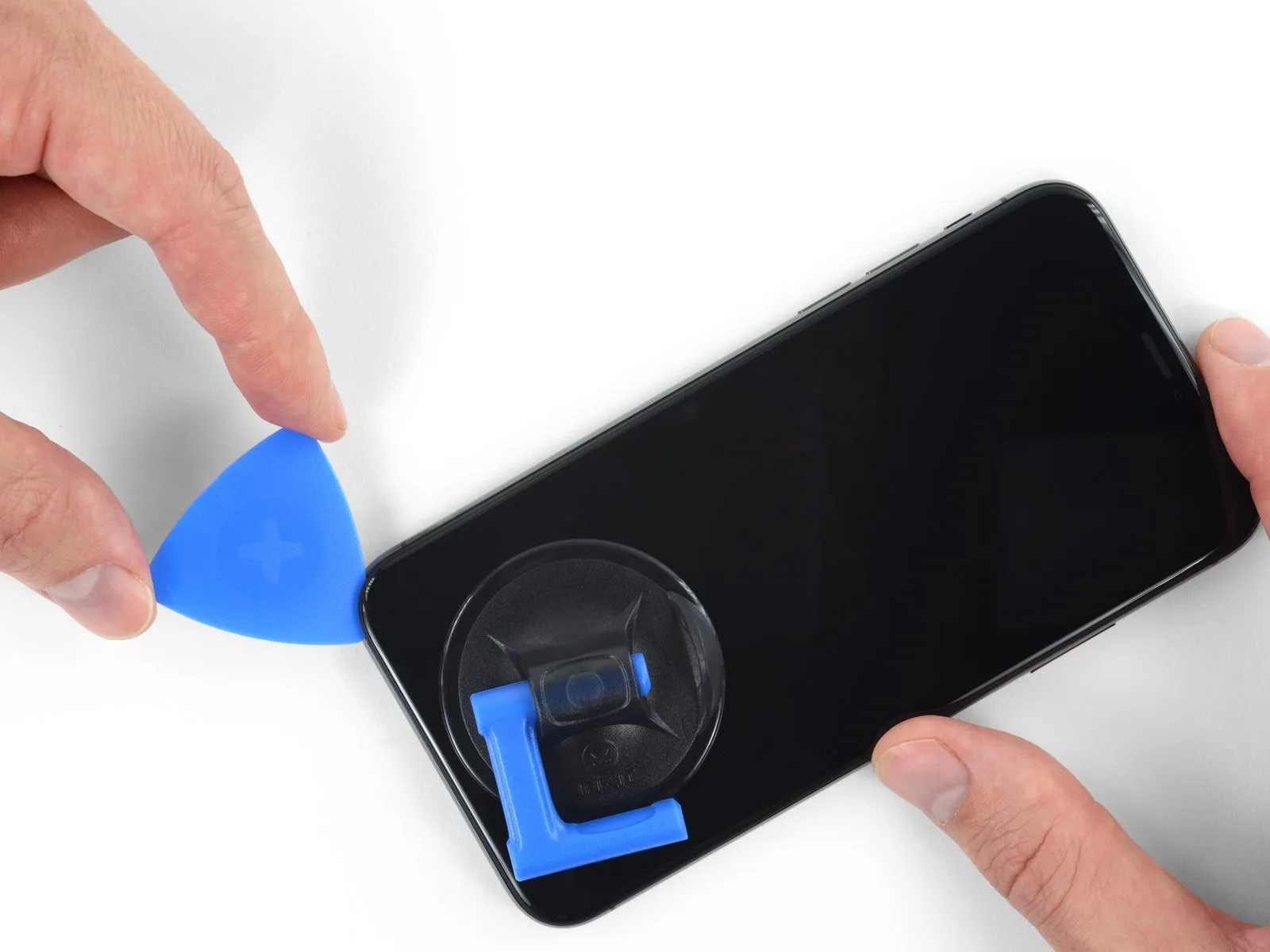
Step 14
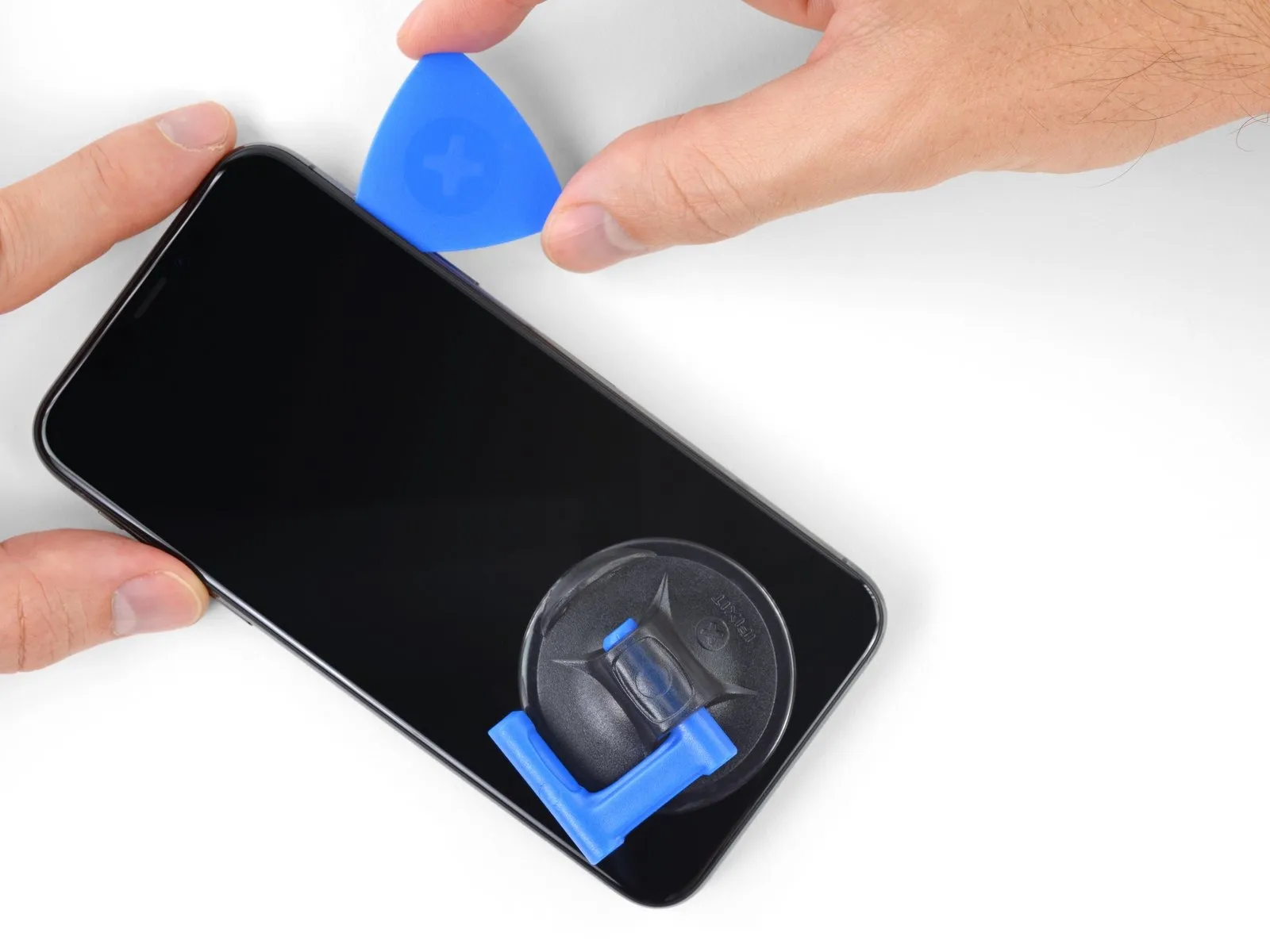
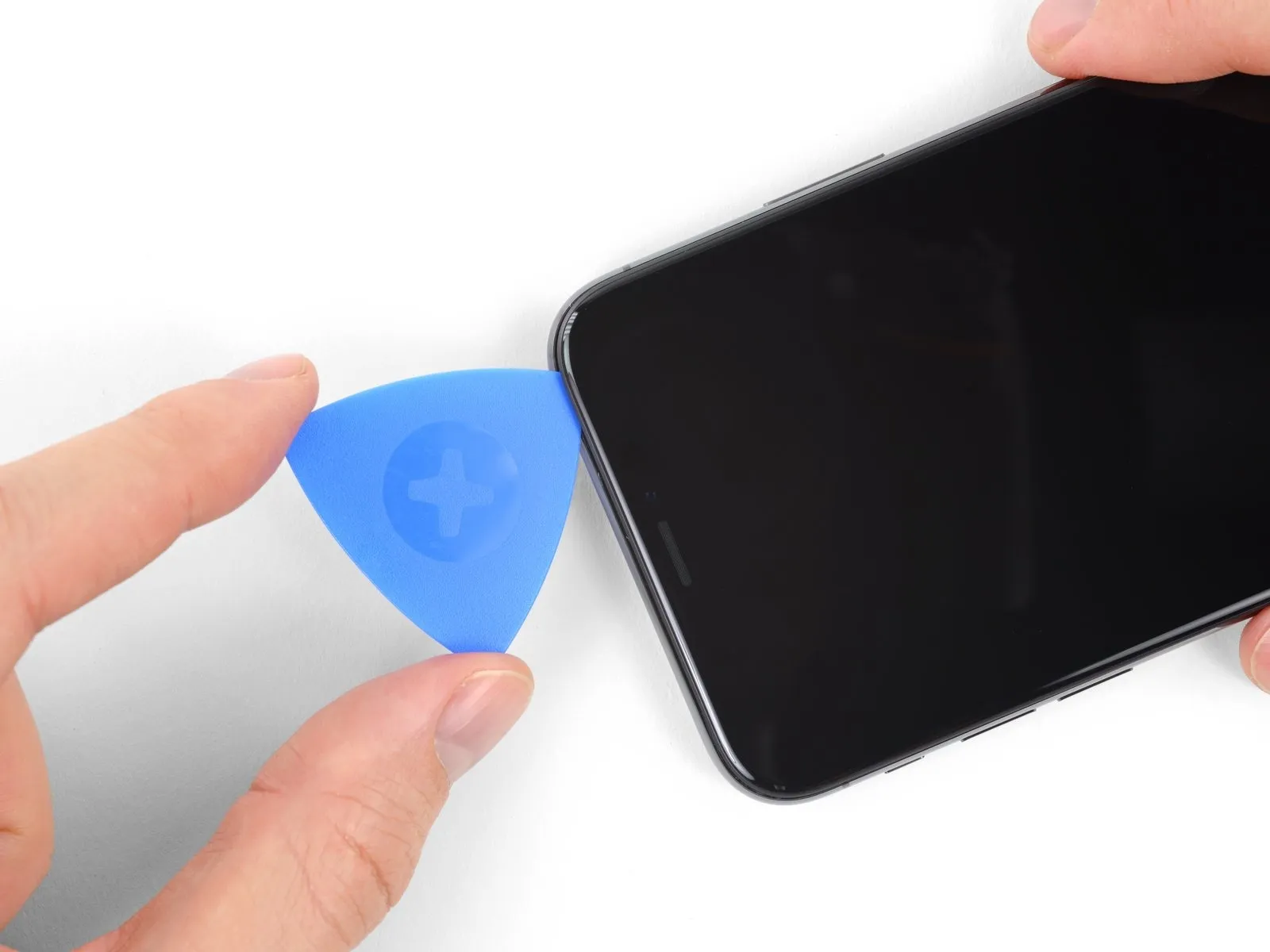
- Using your pick, begin at the lower edge of the iPhone and move it upwards along the right side to release the remaining adhesive.
To prevent damage to the display cables, limit pick insertion depth to a maximum of 3 mm.
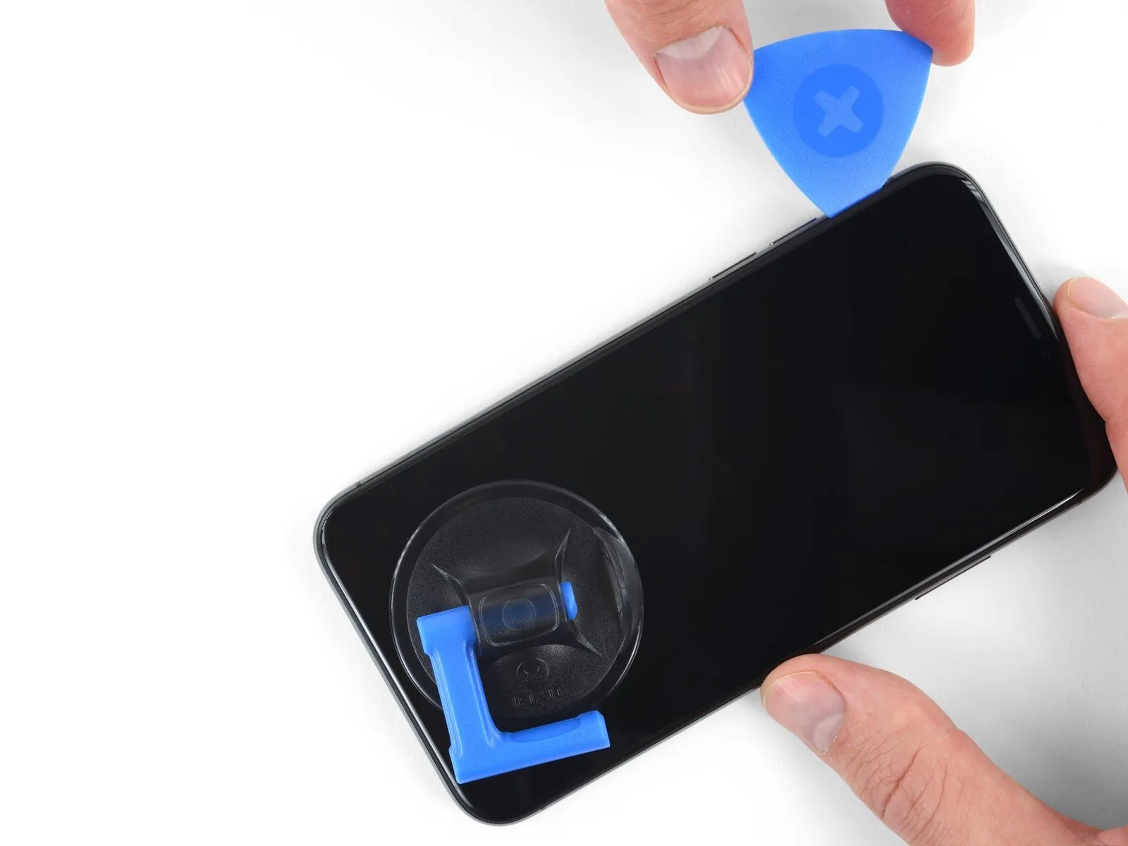
Step 15
- Adhesive and retaining clips both hold the display's upper border in place.
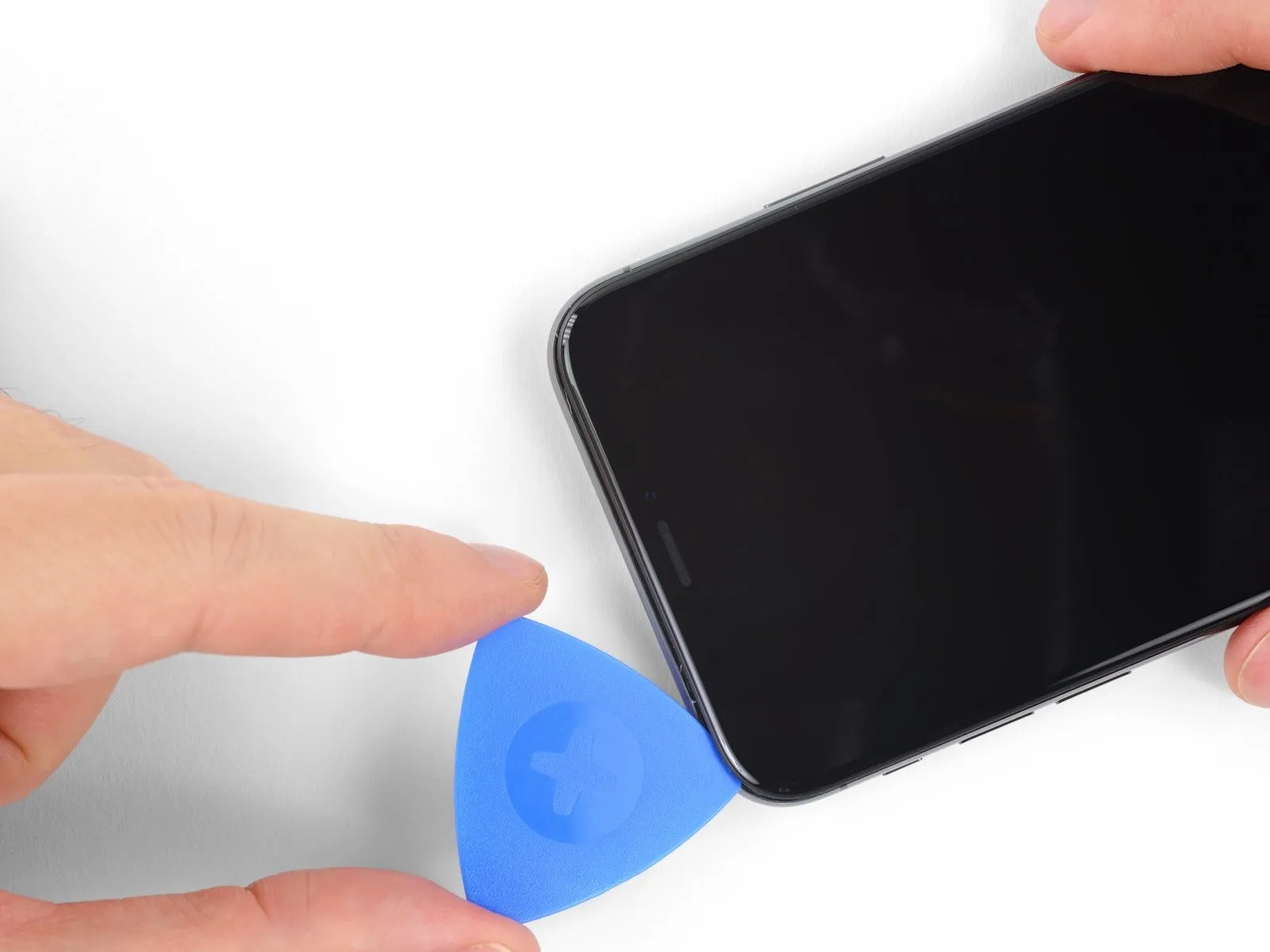
Using a pick, carefully separate the display from the frame at the top corner, applying slight downward pressure towards the Lightning connector as you maneuver the tool.
Excessive force can damage the clips; proceed with caution and allow ample time for the task. - To prevent damage to the front panel sensor array, limit insertion depth of the pick to a maximum of 3 mm.
Using a pick, carefully sever any adhesive bonds still holding the display in place by working towards the opposite corner.
Step 16
- To detach the suction cup, grasp the small projection extending from its surface and apply traction, separating it from the front panel.
Step 17
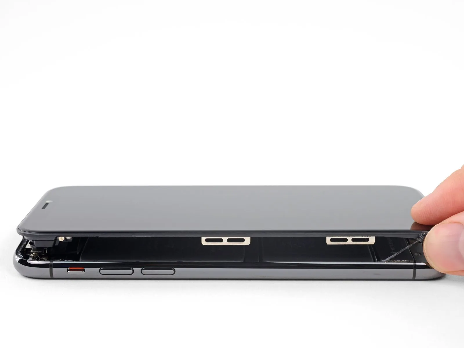
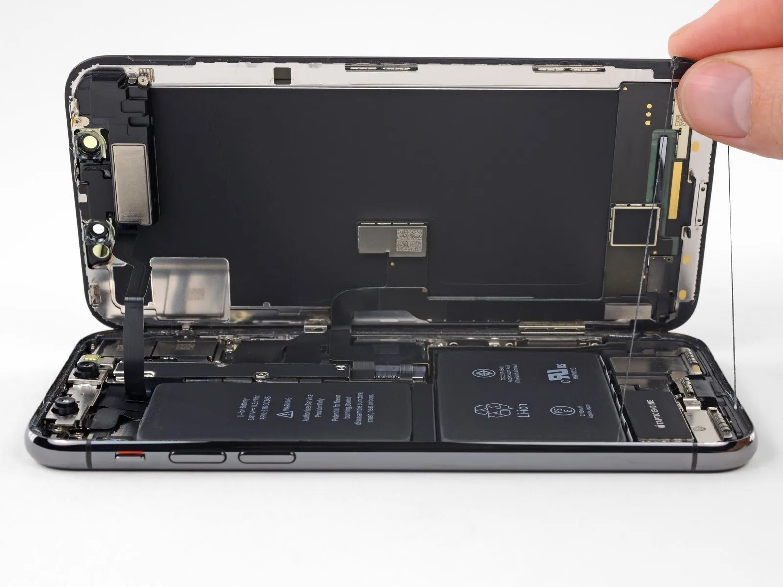
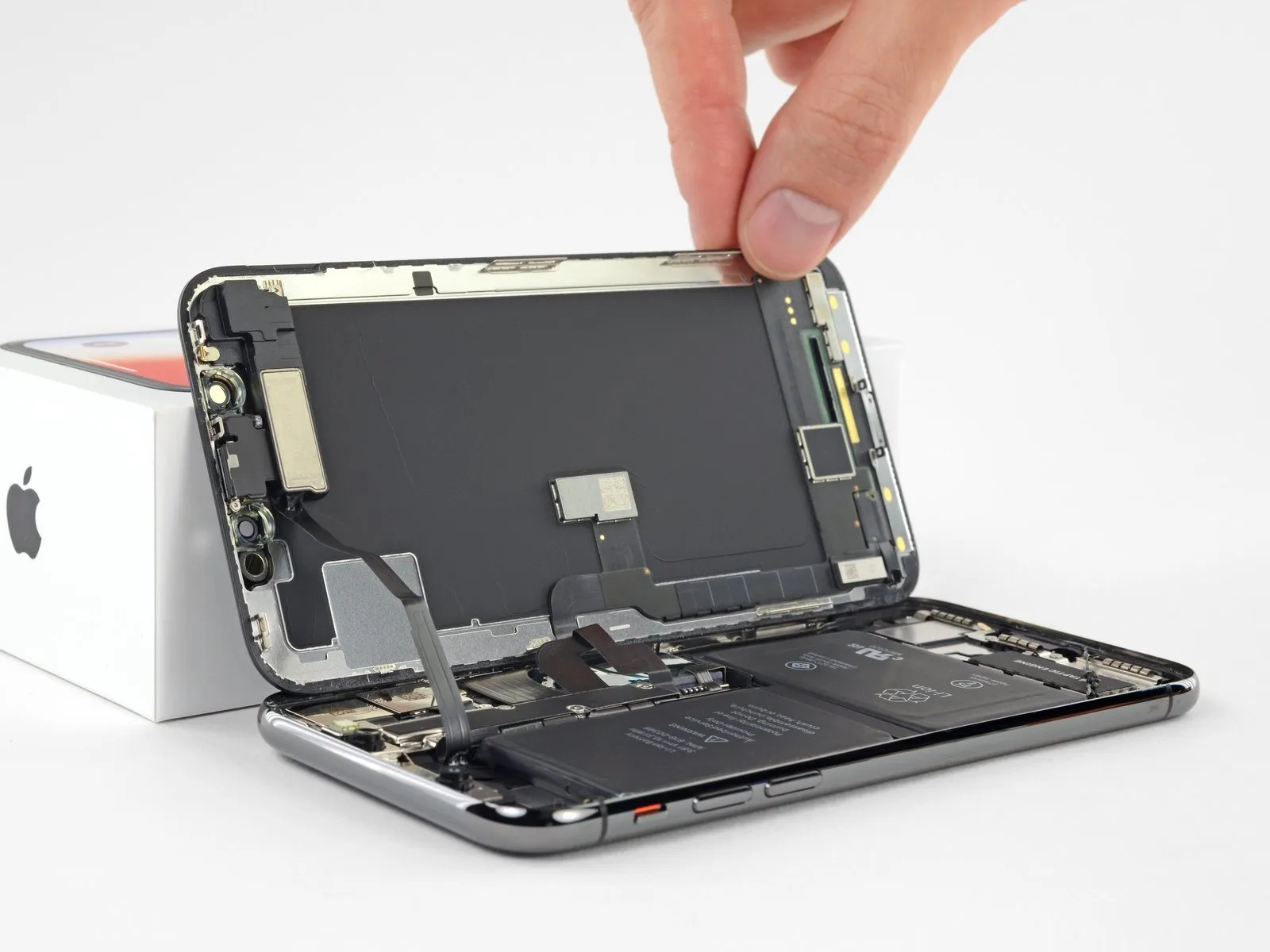
- Using a prying tool, carefully lift the display assembly upwards, initiating the separation from the rear casing along the left edge, mirroring the action of opening a book's cover.
- Before completely disconnecting the display, be aware that multiple delicate ribbon cables, which remain attached to the iPhone’s logic board, require careful handling.
- Carefully detach the frame, ensuring it separates cleanly from the device along with the display assembly, preventing any binding or obstruction.
- To allow hands-free access during the repair process, temporarily support the display using an external object.
- To reassemble, position the display and ensure the top edge clips are properly aligned, then gently push the top edge into its slot before securing the remainder of the display. If resistance is encountered, inspect the display's perimeter clips for any bends and correct them as necessary.
Step 18 | Display Assembly
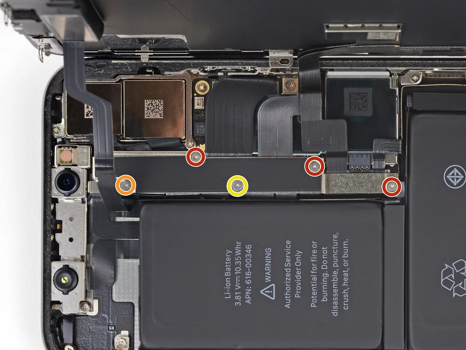
- Using a Y000 screwdriver, detach the bracket that holds the logic board connector by unscrewing the five screws, each measuring a specific length.
Use three screws, each measuring 1.1 millimeters.
A single screw with a 3.1 mm diameter is required.
A single screw, measuring 3.7 millimeters, is required.
Carefully organize all screws during disassembly, noting their original locations, as incorrect reassembly can cause iPhone damage.
Step 19
- Detach the bracket.
Apply minimal pressure to position the bracket; to release it, exert a controlled, upward force.
Before permanently securing the display, it's recommended to activate your iPhone and verify all features are operating correctly; afterward, fully deactivate the device to proceed with the remaining assembly steps.
Step 20
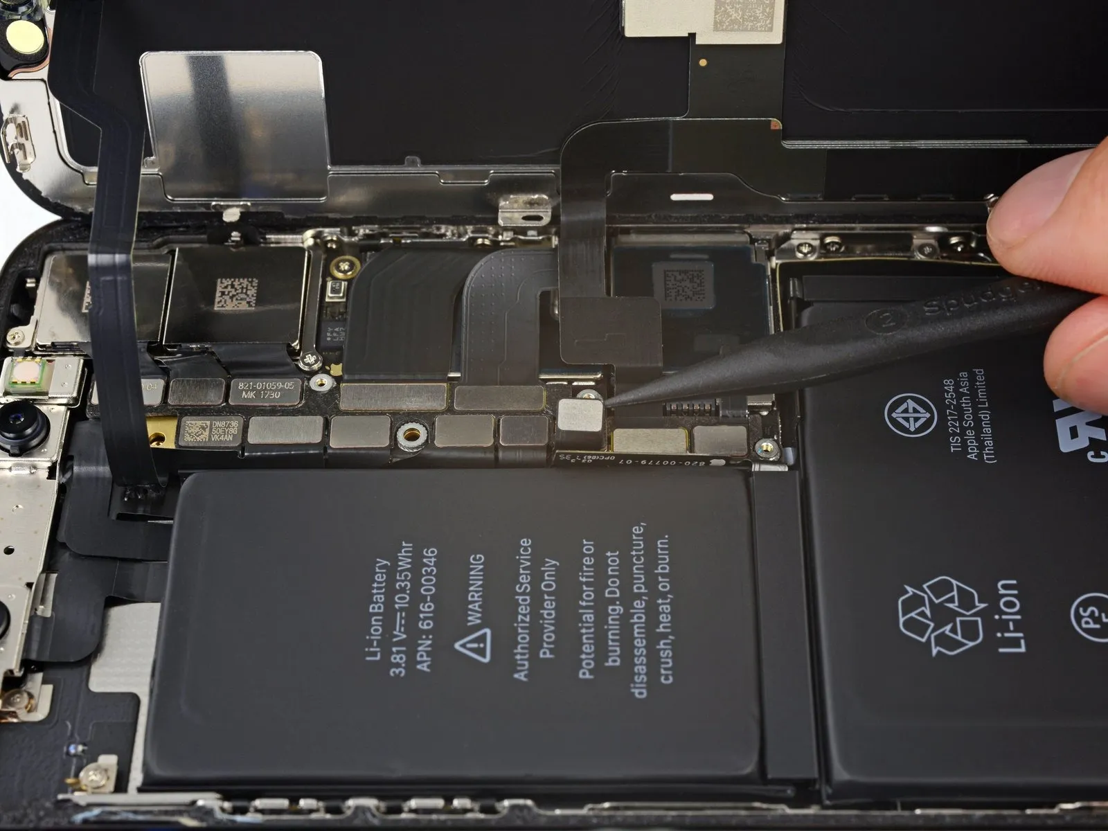
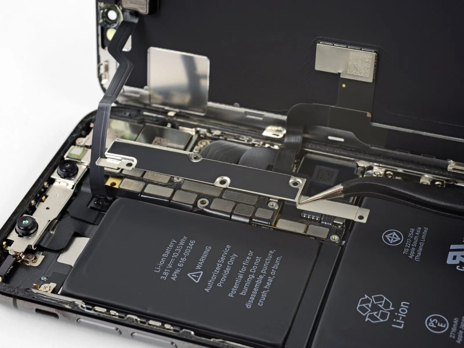
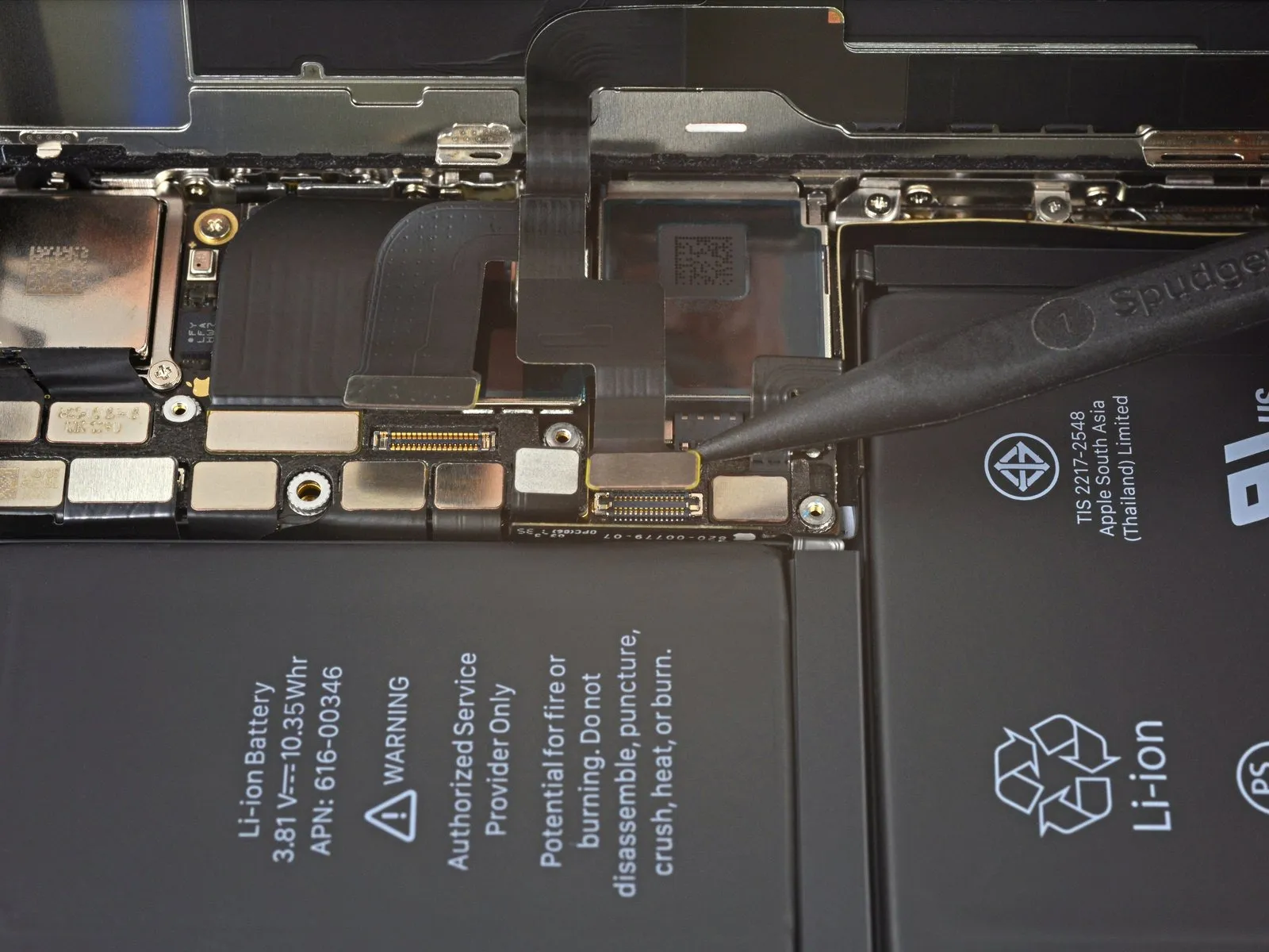
- Carefully lift the battery connector's retaining clip on the logic board using a spudger tip or a similar non-marring tool to release it.
To prevent water and dust from entering, exercise caution to avoid harming the black silicone seals located around this and other circuit board interfaces.
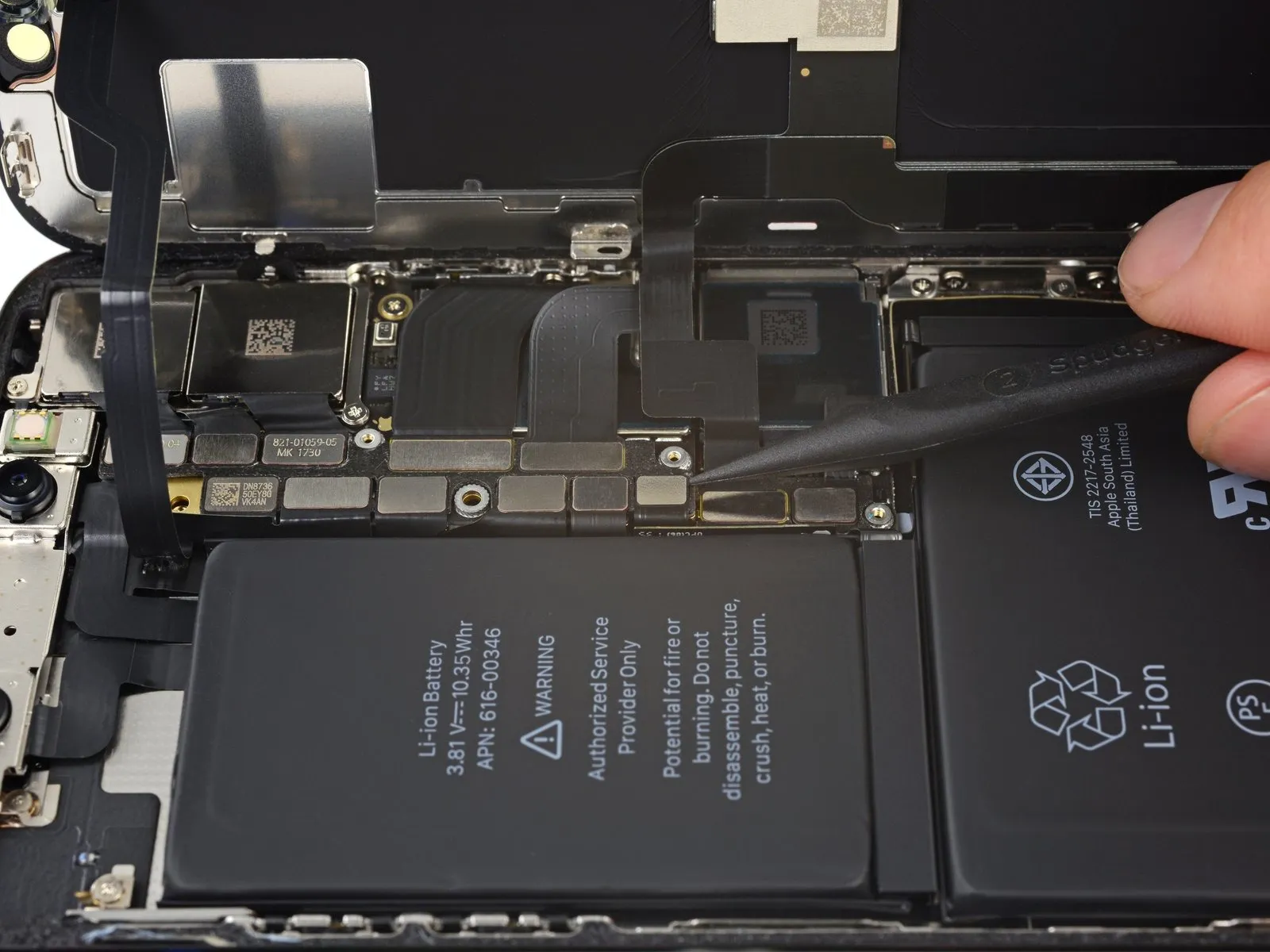
To avoid unintended power-up during the repair process, carefully angle the connector outward, distancing it from the socket and the logic board.
Step 21
Step 22
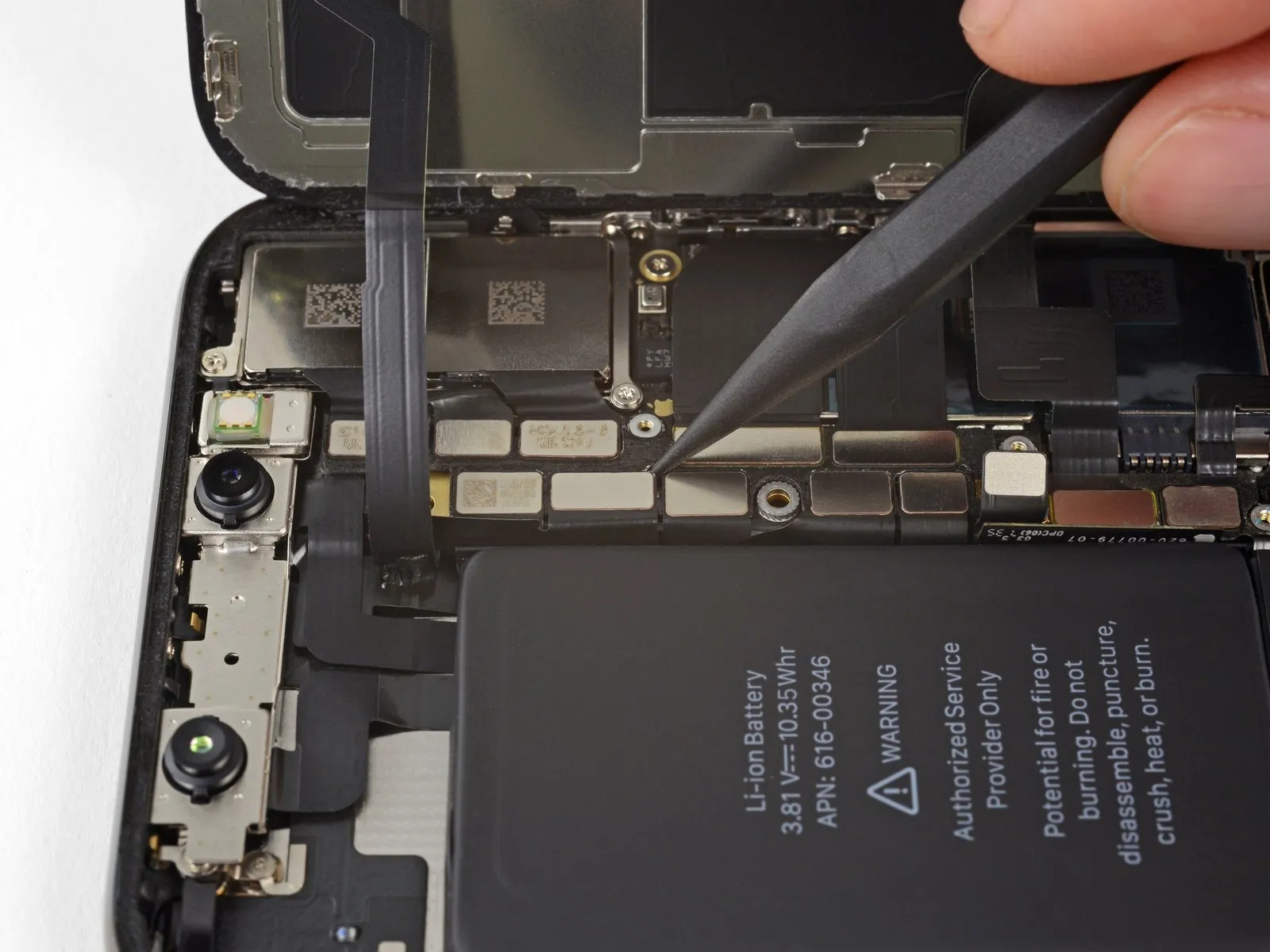
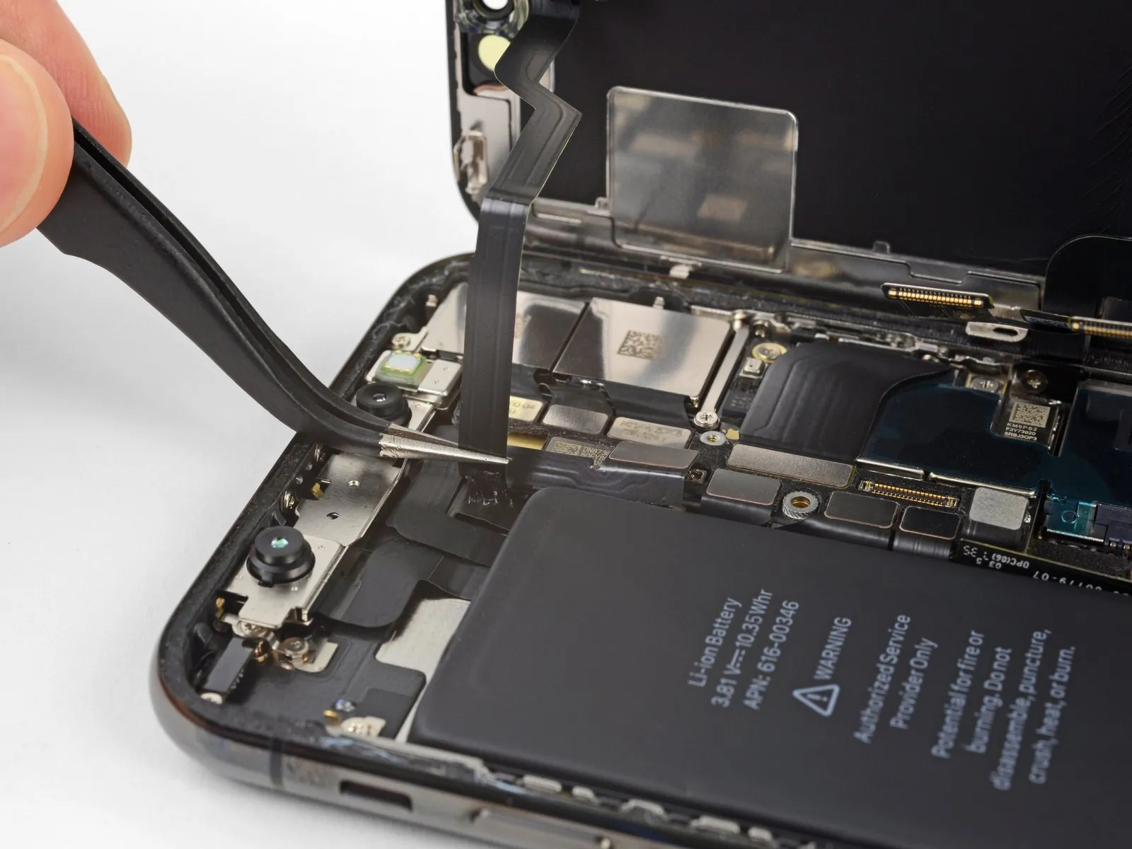
- Carefully insert the tip of a screwdriver to.Use a plastic pry tool, often referred to as a spudger, to avoid scratching surfaces.This instruction is incomplete and lacks context. I cannot rewrite it without the original sentence/instruction. Please provide the full text.Use a fingernail.Carefully detach the OLED panel cable connector.
- Ensure proper alignment before applying even pressure to one edge of the connector until you hear a click, then repeat the process on the opposite edge. Avoid applying pressure to the central portion; misalignment risks bending the internal pins, potentially resulting in irreparable harm.
Step 23
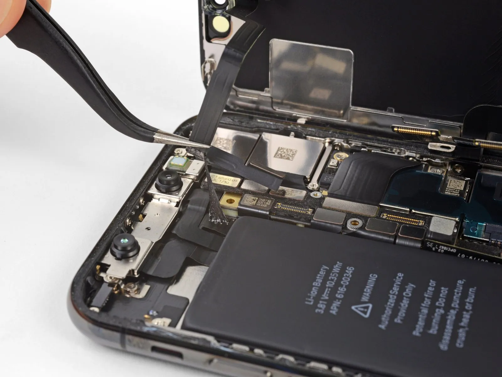
- Carefully employ the tip of a screwdriver to apply pressure.Use a plastic pry tool, often referred to as a spudger, to gently separate components.Carefully use a prying tool to lift the digitizer cable connector vertically from its corresponding socket.
- Due to the connector's set-back position, reconnection can be challenging; meticulous alignment is essential, followed by a gradual, fingertip-applied pressure, initially on one side and subsequently on the other, until a distinct clicking sound confirms secure engagement.
- Following the repair, if the touchscreen exhibits unresponsive areas, first detach the battery, then carefully remount this connector, verifying a secure, audible click and confirming the socket is free from dust or debris.
Step 24
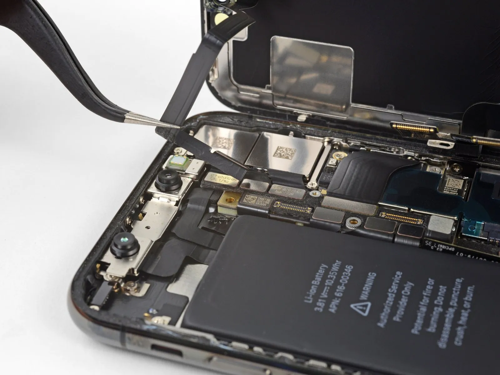
The adhesive securing the front panel sensor assembly's flex cable is applied with minimal force.
Gently raise the cable, ensuring the adhesive bond releases.
Step 25
- Carefully detach the display assembly, ensuring no damage occurs.
- If a display seal replacement is desired, halt the reassembly process at this point to apply fresh waterproof adhesive to the display's perimeter.
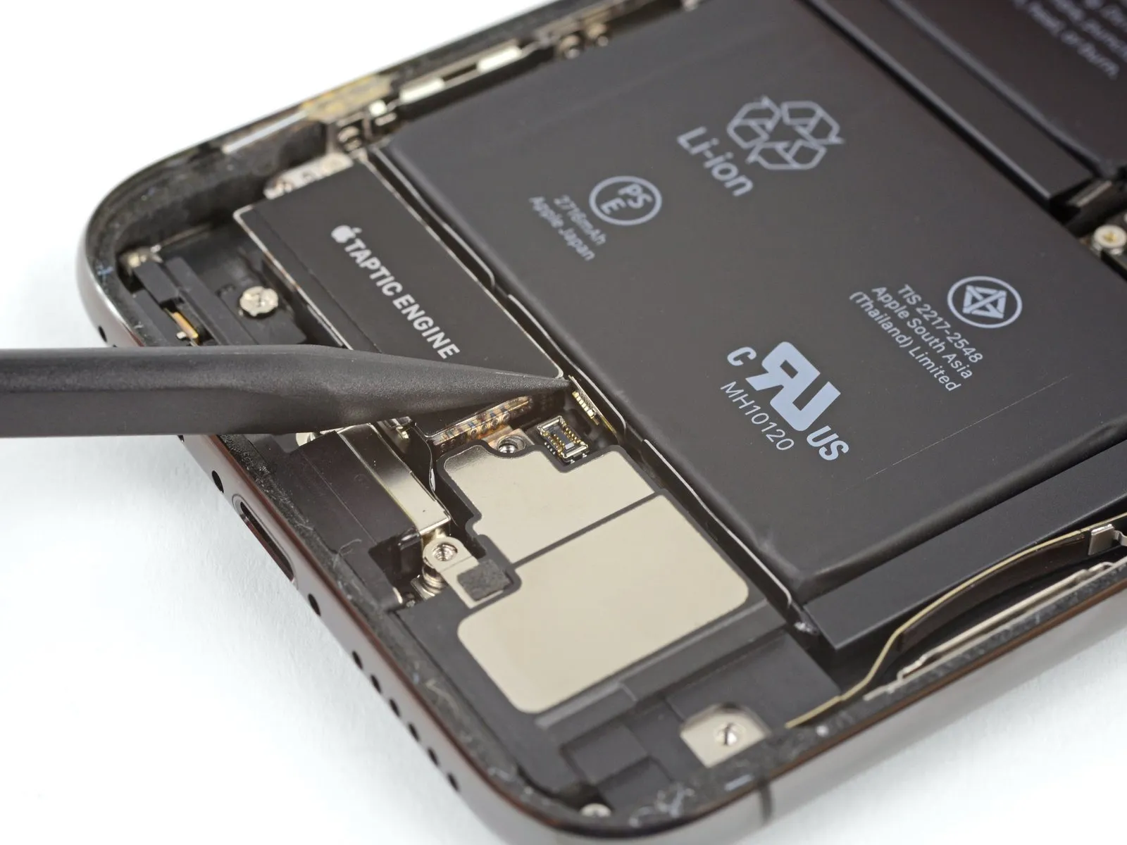
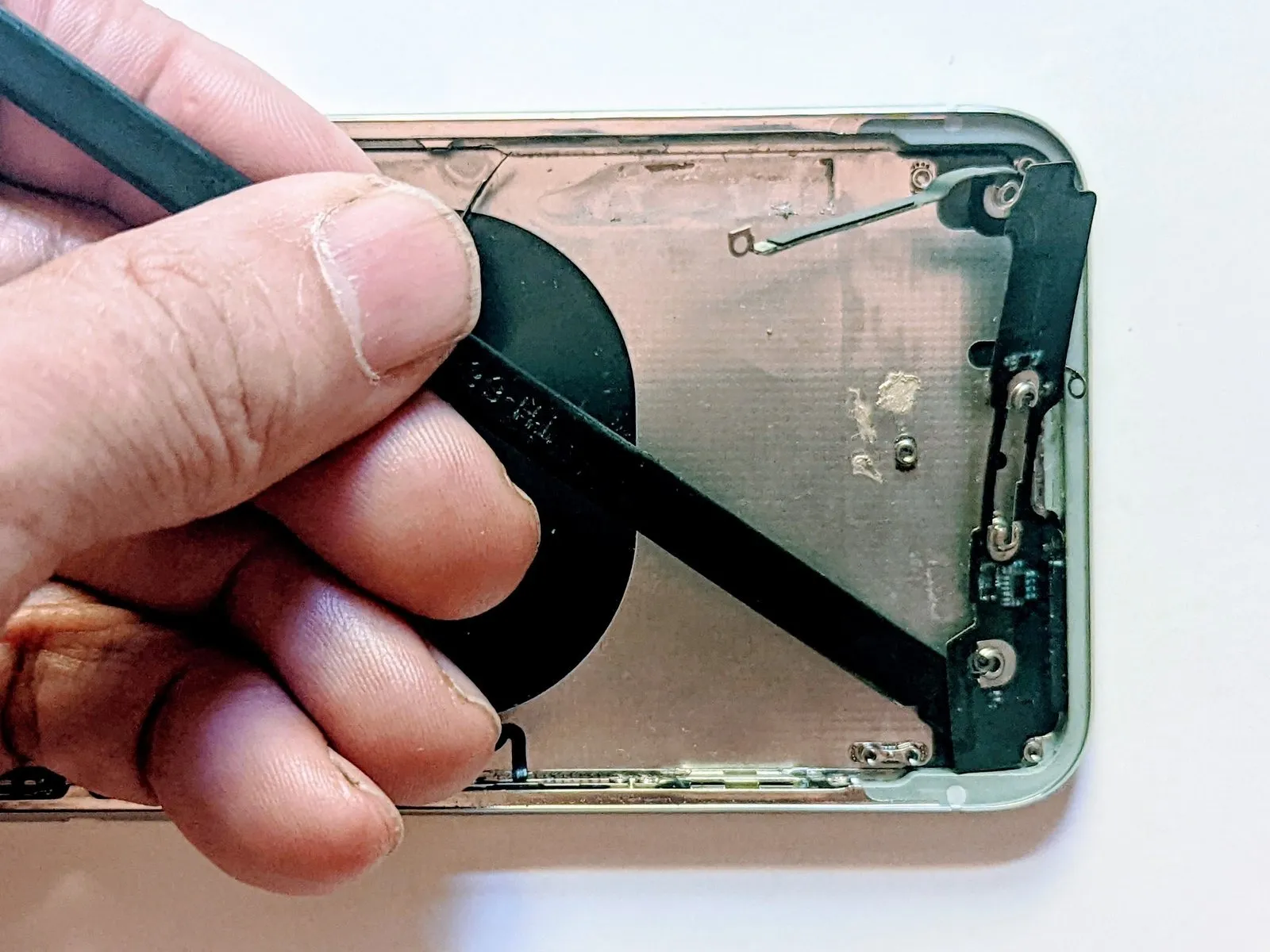
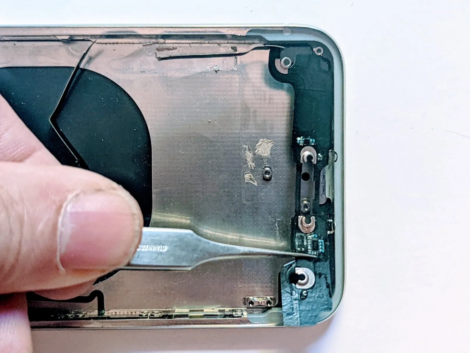
Step 26 | Lower Speaker
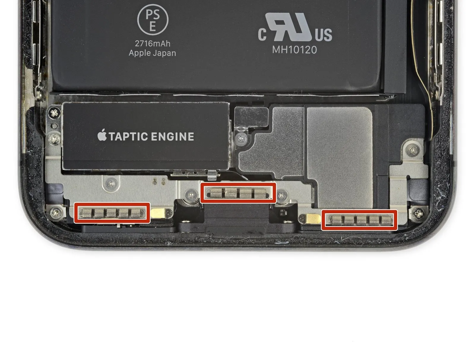
- Avoid contact with the three rows of grounding pads located at the iPhone's base to prevent damage.
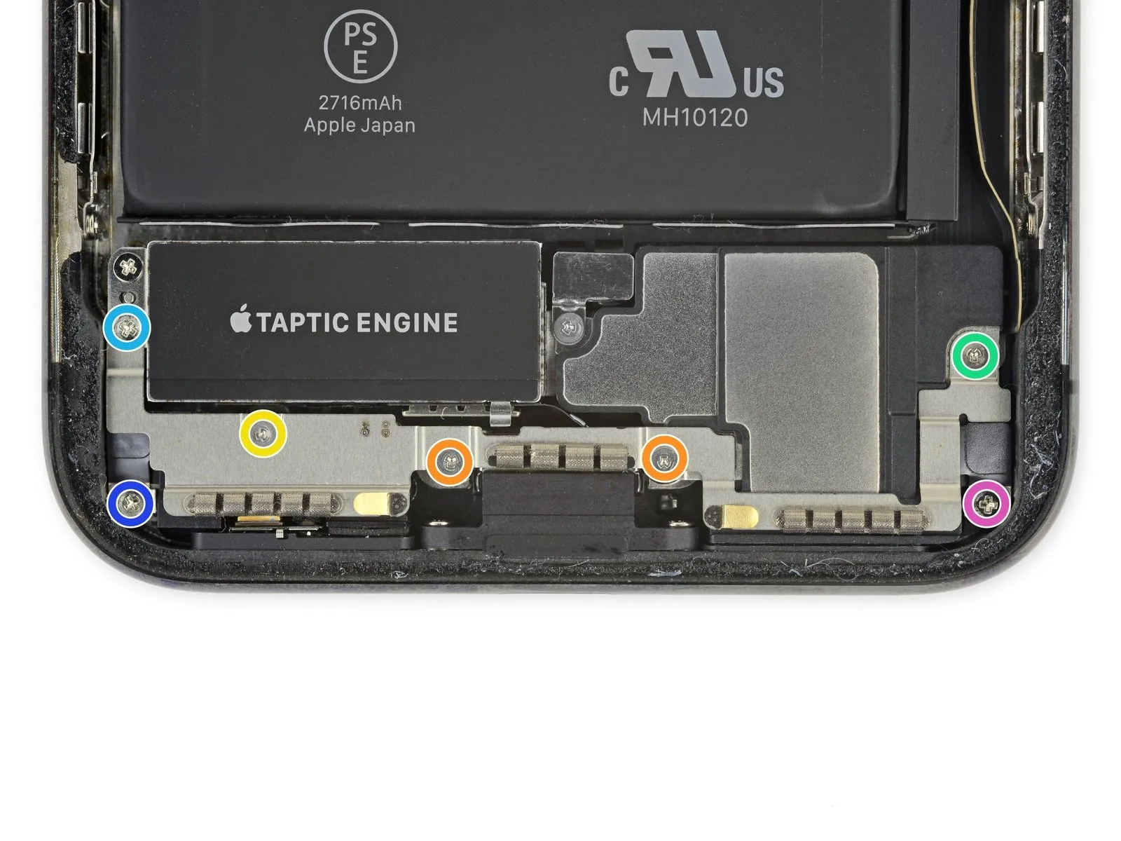
- Using appropriate tools, detach the bracket located beneath the Taptic Engine and speaker assembly by unscrewing the seven fasteners that hold it in place.
- Use two screws, each with a Y000 head and measuring 1.9 mm.
- A 1.2 mm screw of Y000 head type is required.
- A 1.6 mm screw of Y000 type is required.
- A 2.4 mm Phillips head screw is required.
- A single screw, requiring a Phillips driver with a 1.7 mm tip, is needed.
- A single screw, requiring a Phillips head screwdriver with a 1.5 mm tip, is needed.
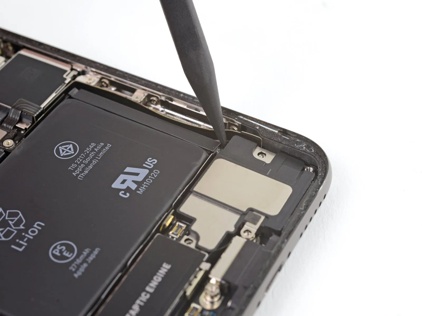
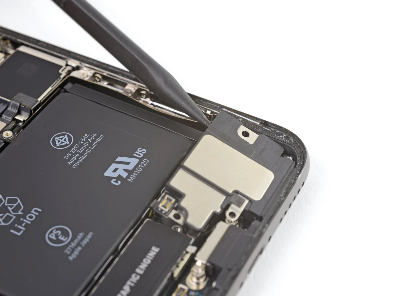
Step 27
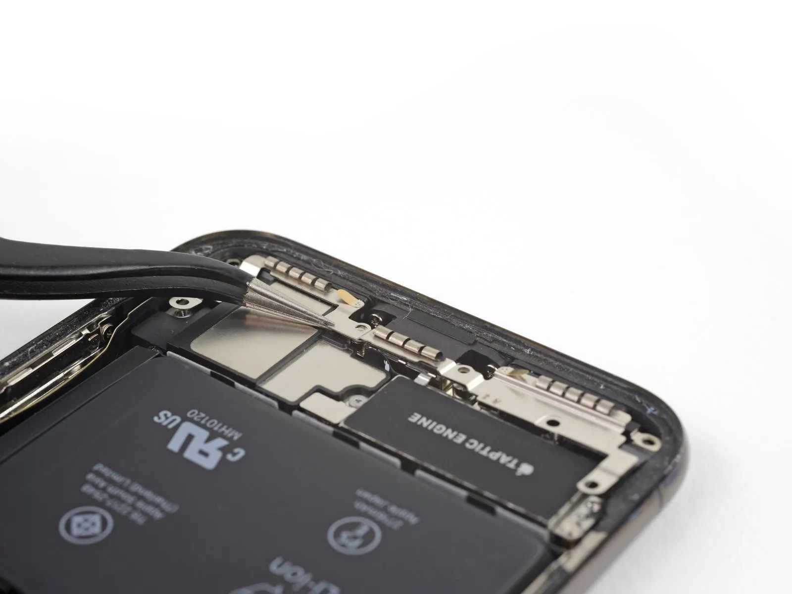
- Carefully raise the bracket, positioning yourself closest to the battery.
- Avoid complete detachment, as a short flexible cable maintains the electrical connection.
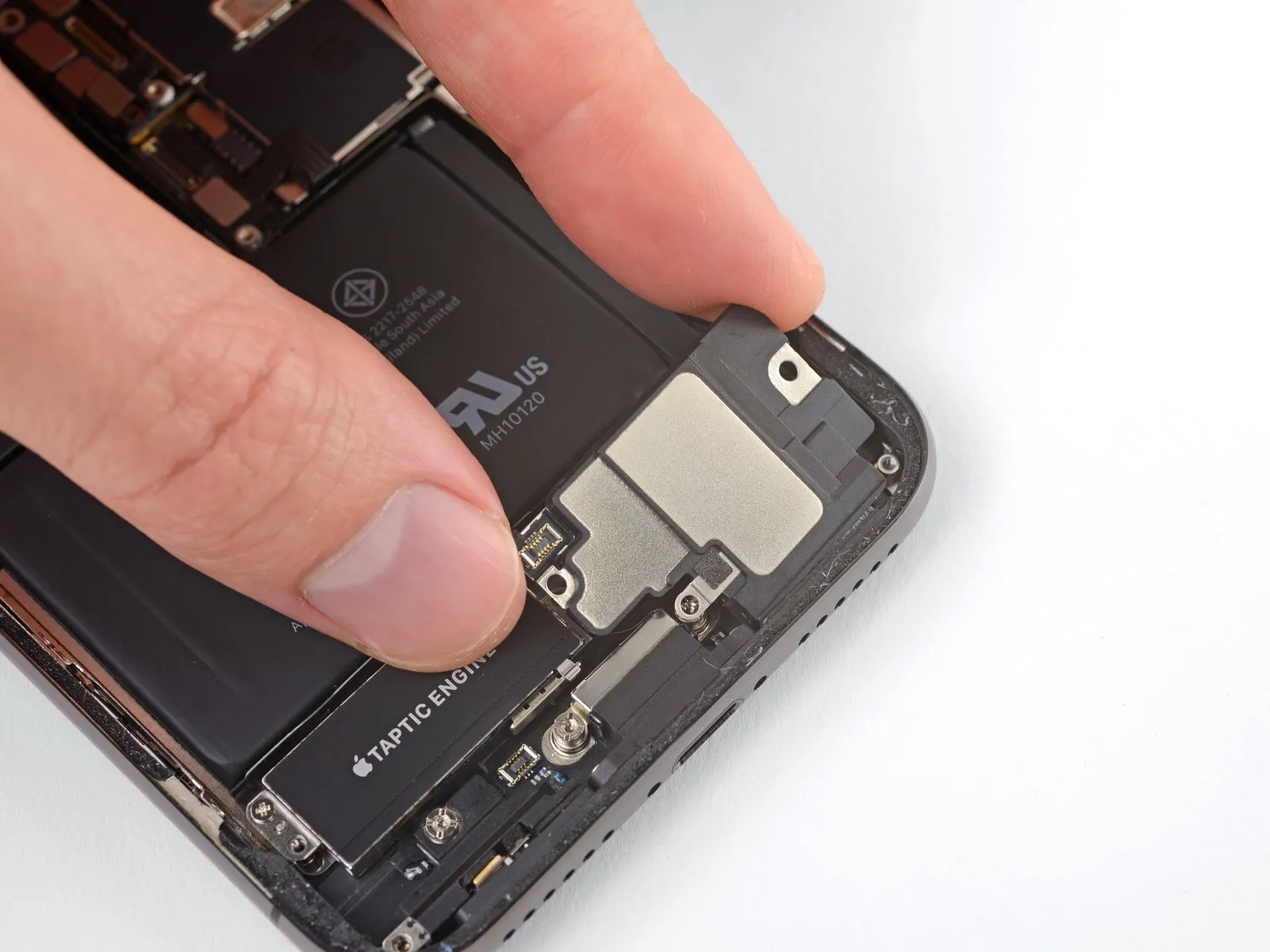
Step 28
- Carefully position the bracket to prevent interference, then utilize a spudger tip to gently lift and detach the flex cable located beneath it.
Step 29
Step 30
- Carefully detach the component, ensuring all associated fasteners are released and any specified torque values are adhered to during reinstallation.Use a Y000 screwdriver to remove the 2.1-millimeter screw.Affix the speaker connector cover, ensuring it is properly aligned and fastened to retain the connector.
Step 31
Step 32
- Employ the pointed end of a screwdriver.Use a plastic pry tool, often referred to as a spudger, to gently separate components.Use a prying tool to release and separate the speaker connector.
Step 33
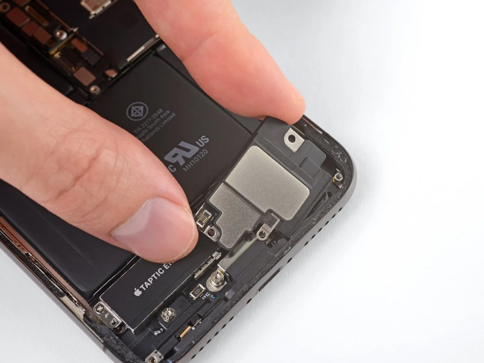
To prevent damage to the recently detached flex cable, carefully separate the speaker and, if needed, support the cable to allow for speaker removal.
- Using a spudger, gently slide it between the speaker's top edge and the iPhone's casing perimeter.
- Using careful, controlled force, raise the speaker's upper border by separating it from the surrounding structure.
Before securing the speaker, verify the flex cable's placement to prevent it from being pinched or compressed during reassembly.
Step 34
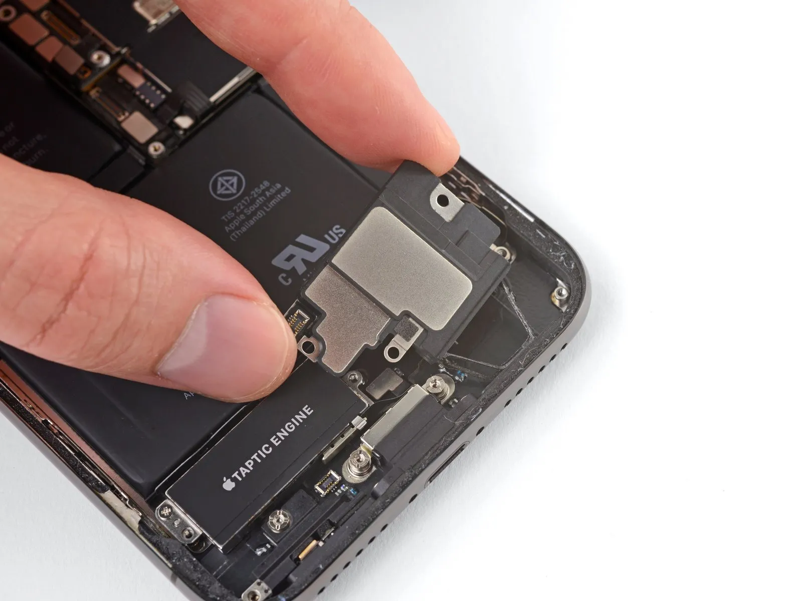
Gently dislodge the speaker from the iPhone's bottom edge by grasping it along its sides and applying a slight, alternating back-and-forth motion to break the adhesive bond.
- Carefully disengage the speaker from the iPhone's lower edge by releasing the adhesive gasket.
Step 35
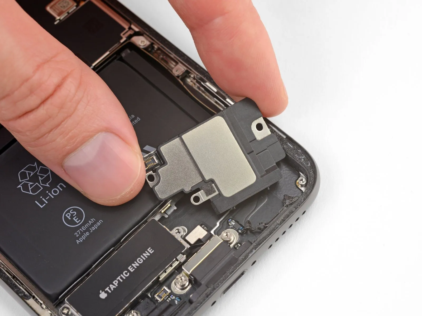
Carefully detach the speaker component.
Step 36 | Replace the speaker gasket
When reassembling, a new gasket must be used for the speaker, as the original is designed for single use only.
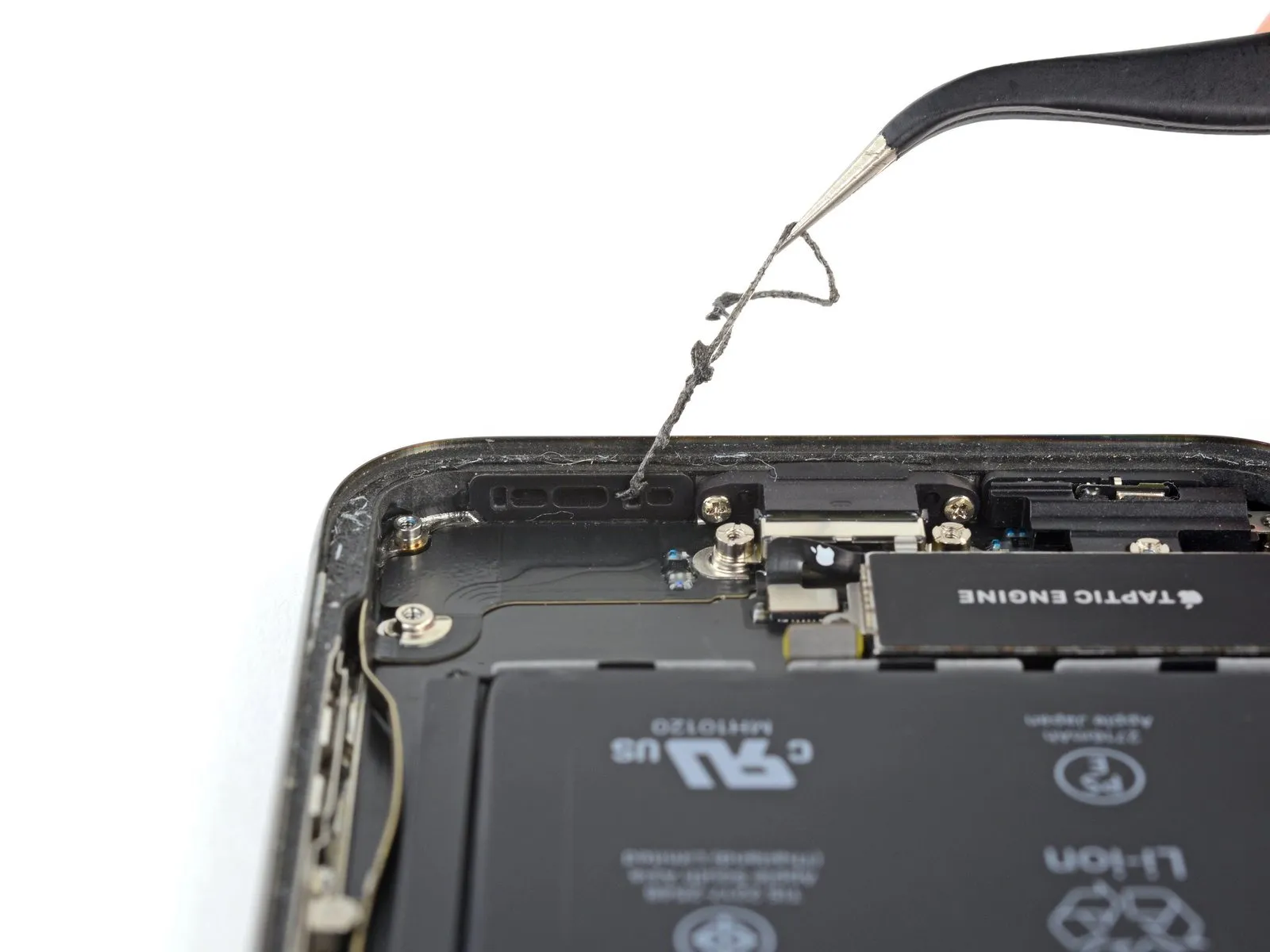
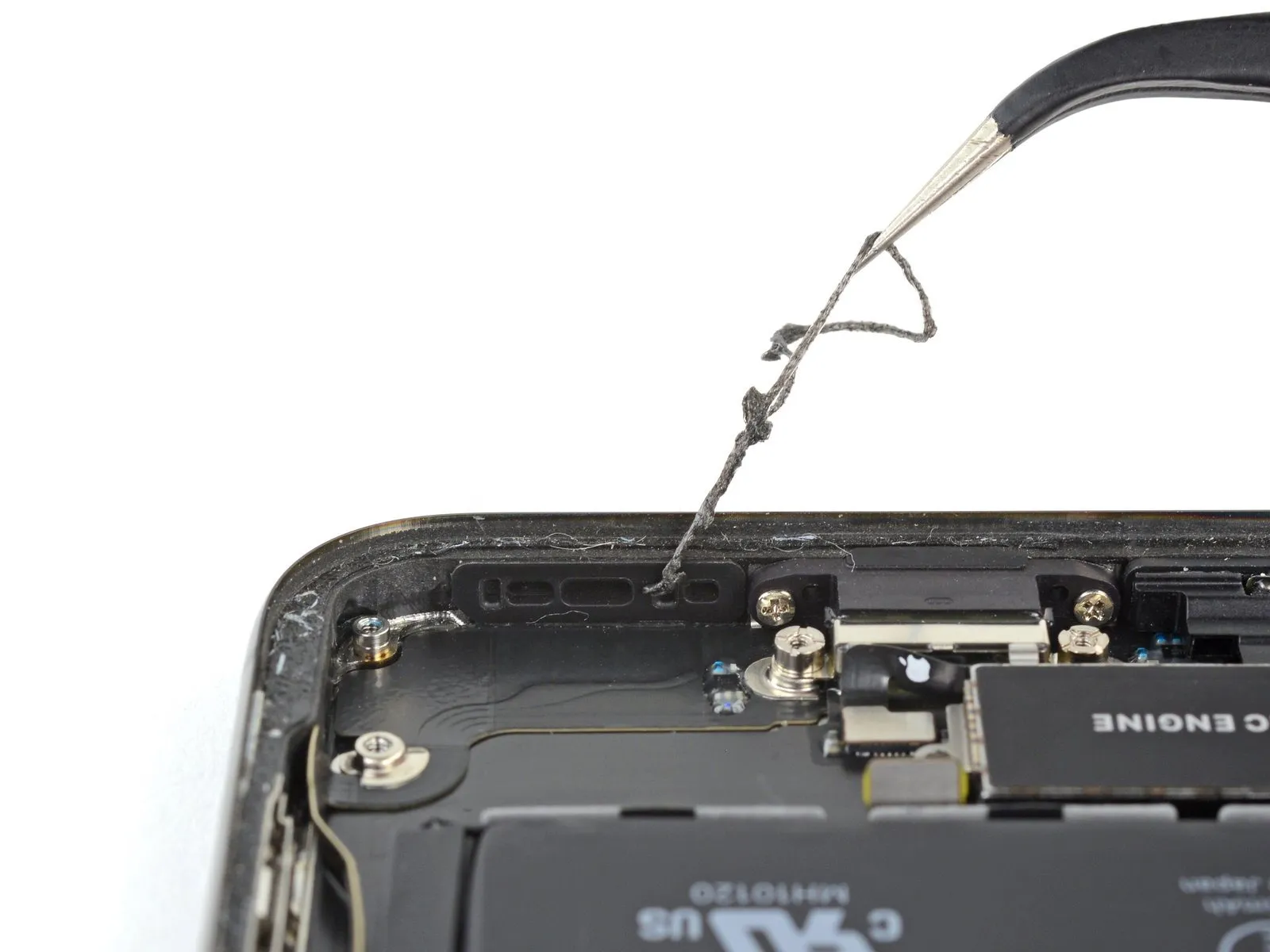
- Carefully detach and eliminate all remnants of the existing gasket from both the frame and speaker assembly, employing tweezers for precise manipulation.
- Employ a microfiber cloth dampened with isopropyl alcohol to thoroughly remove any remaining adhesive from both the frame and speaker surfaces where the gasket was previously situated.
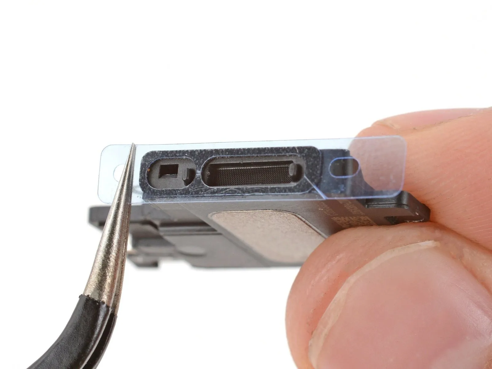
- Ensure the new gasket is positioned correctly before installation; align it so the larger opening is situated around the speaker grille's mesh.
- Carefully extract the transparent liner from the gasket, then position the gasket precisely onto the speaker's bottom surface using tweezers.
- Handle the gasket exclusively by its outer liner borders to prevent contact with the adhesive underneath.
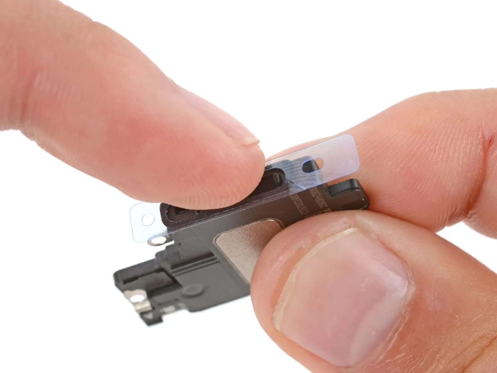
- Ensure the gasket is properly seated and bonded by applying consistent pressure with your fingers or a spudger.
- Carefully extract the remaining liner, then position the speaker, ensuring the speaker connector remains free from obstruction.
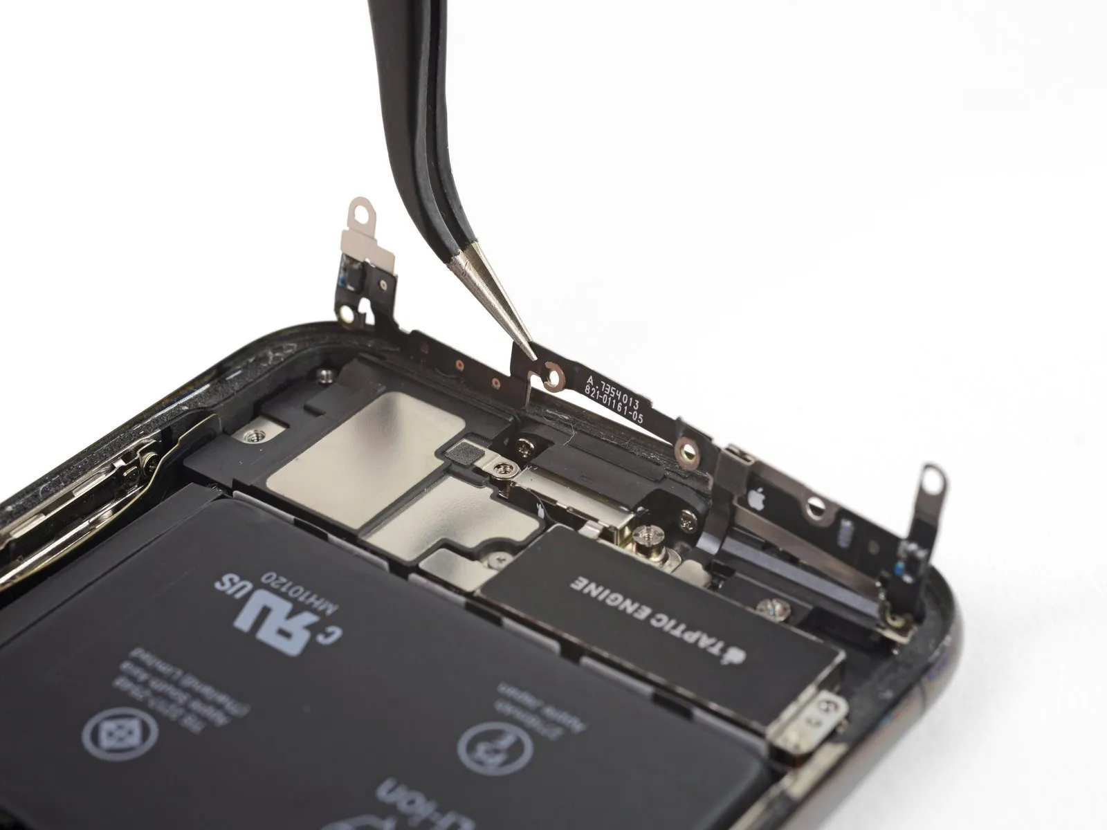
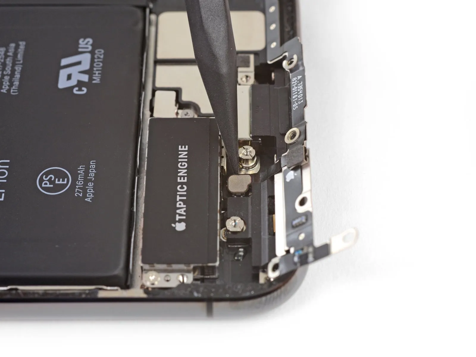
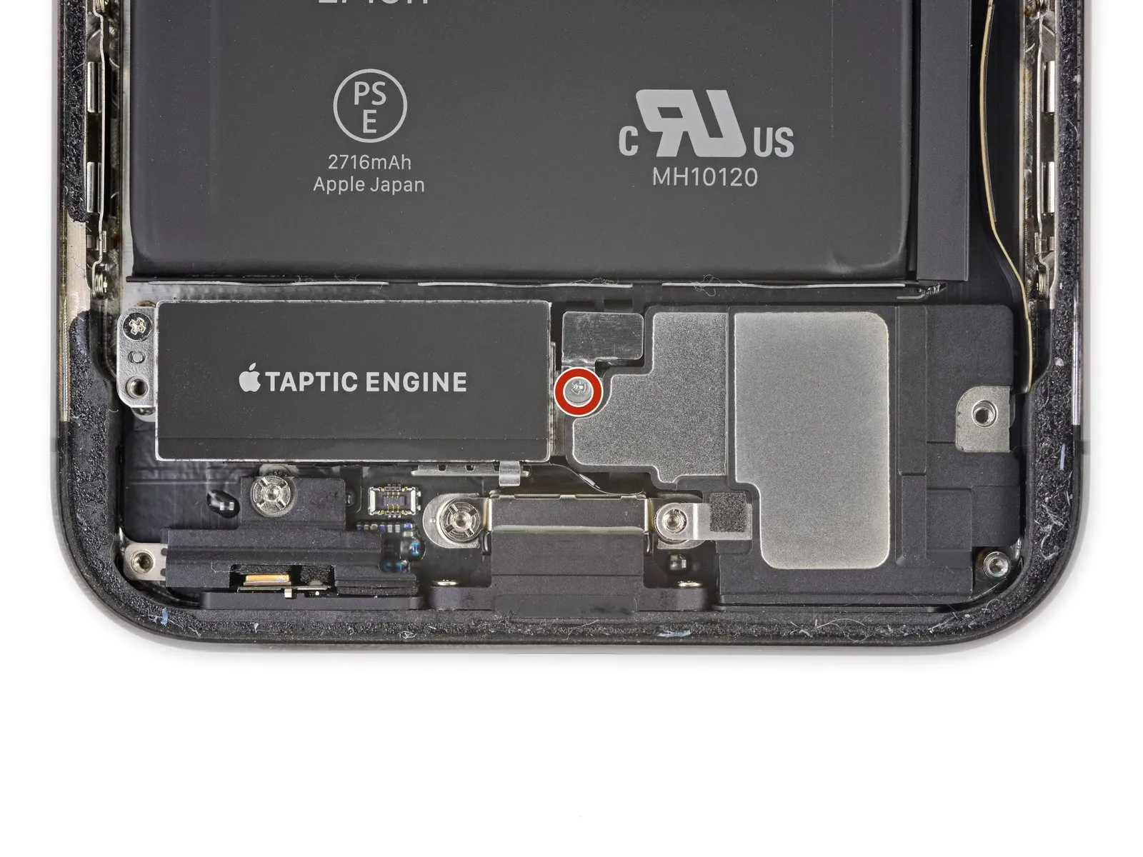
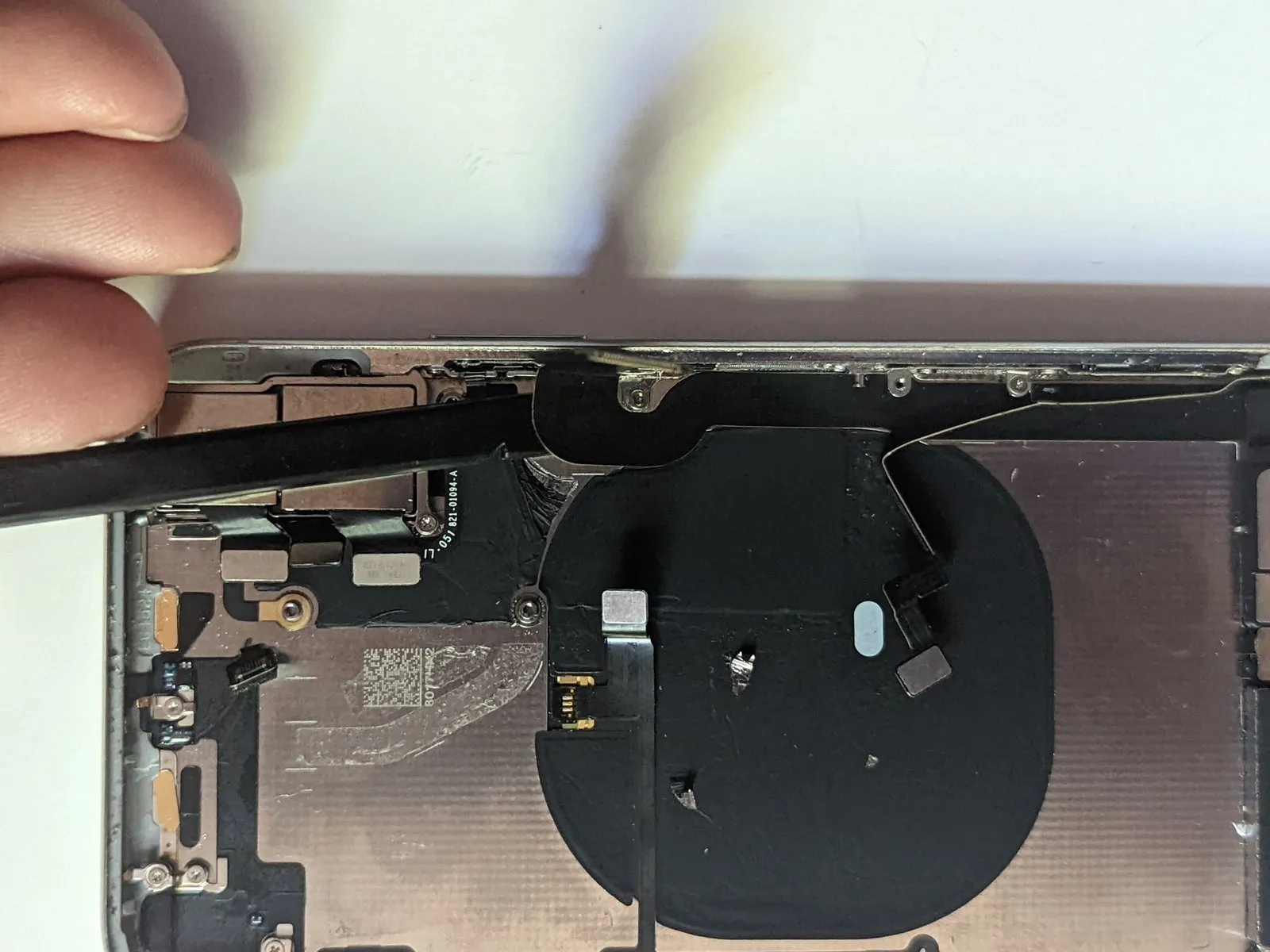
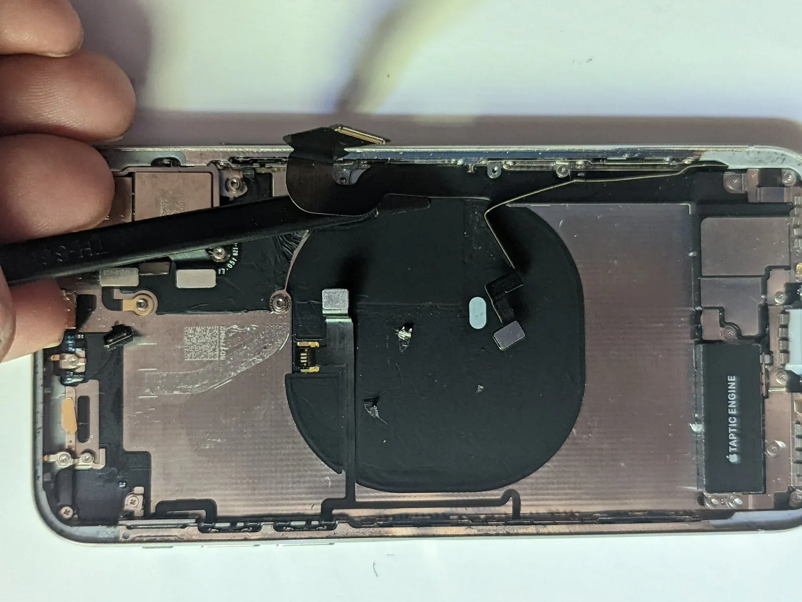
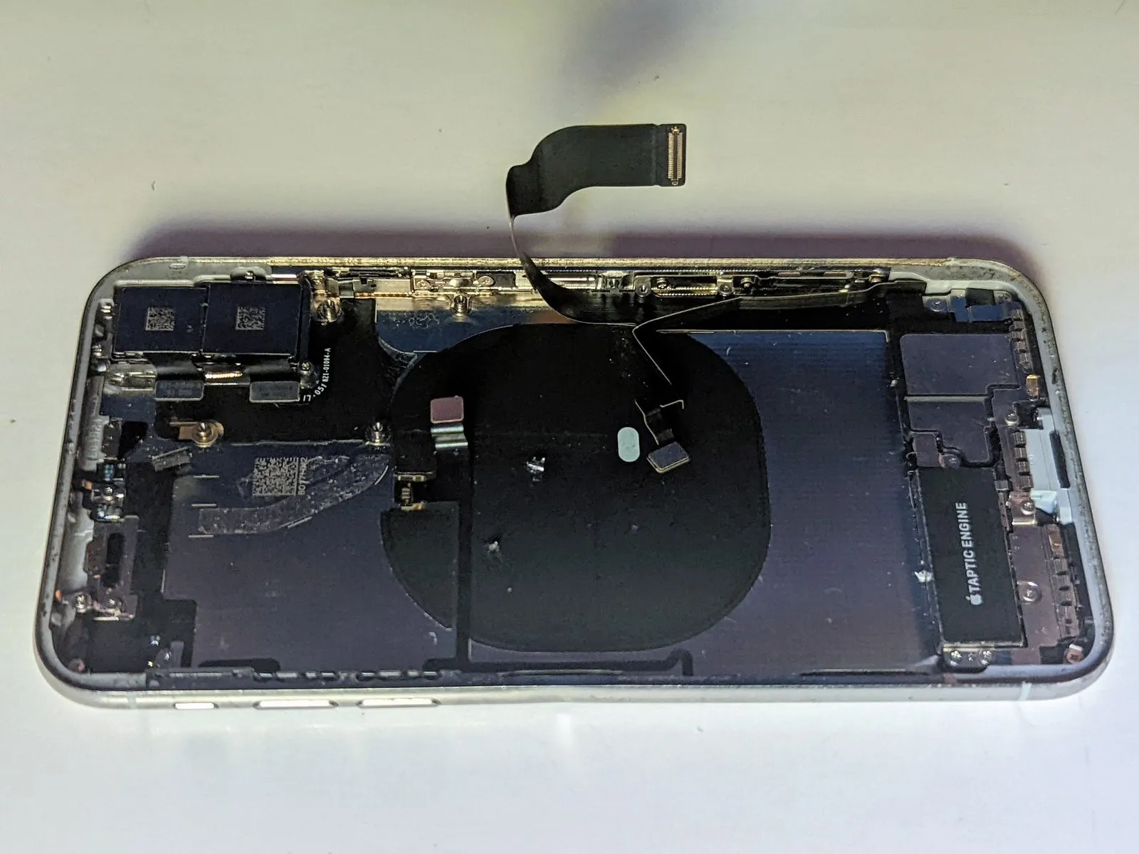
Step 37 | Taptic Engine

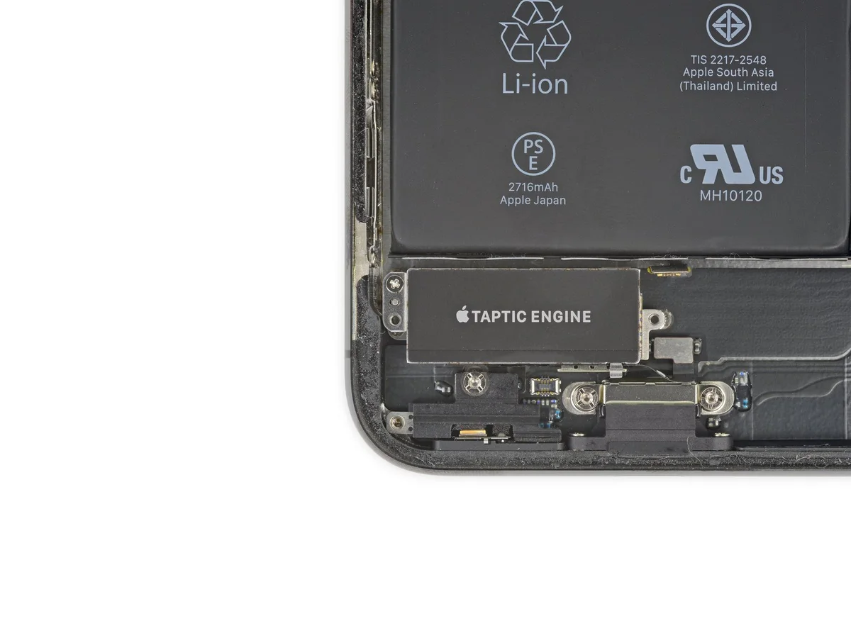
- Carefully detach the component, ensuring all original fasteners are retained for reassembly.Use a Phillips screwdriver with a 2.3-millimeter tip.Use the Torx T5 screwdriver to fasten the Taptic Engine with the provided screws, ensuring each is tightened to a torque of 1.2 Nm.
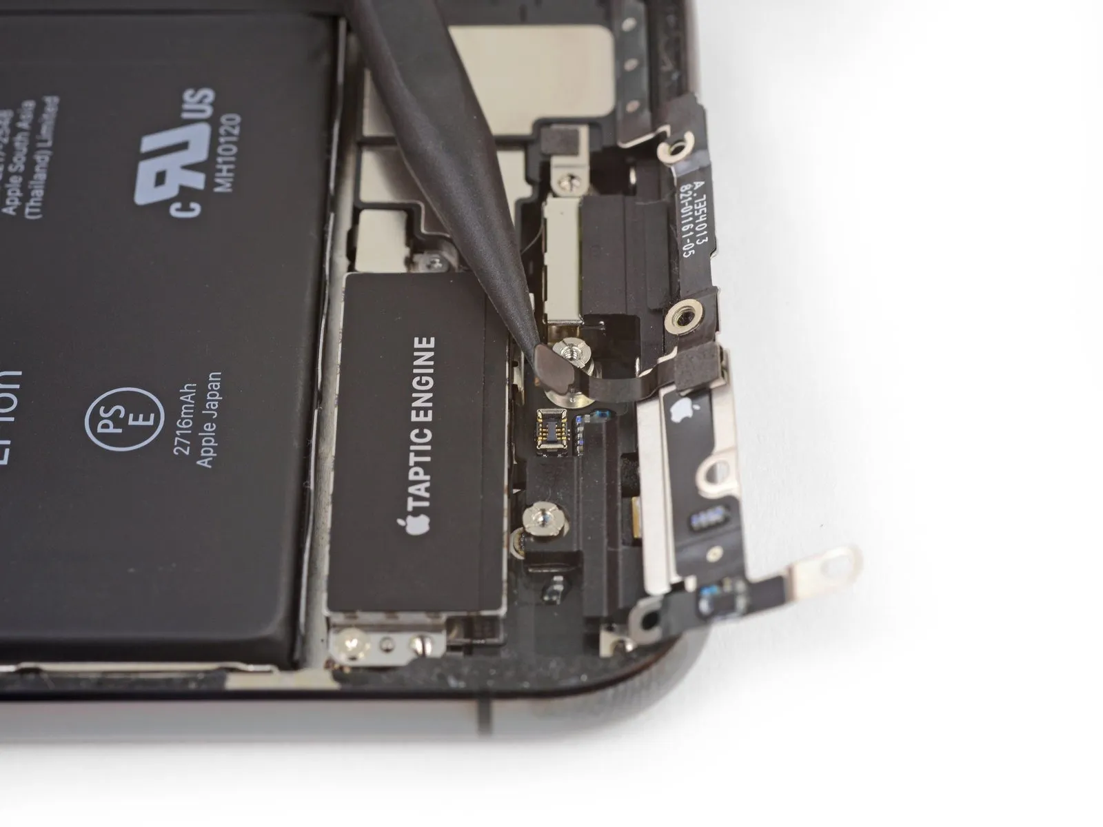
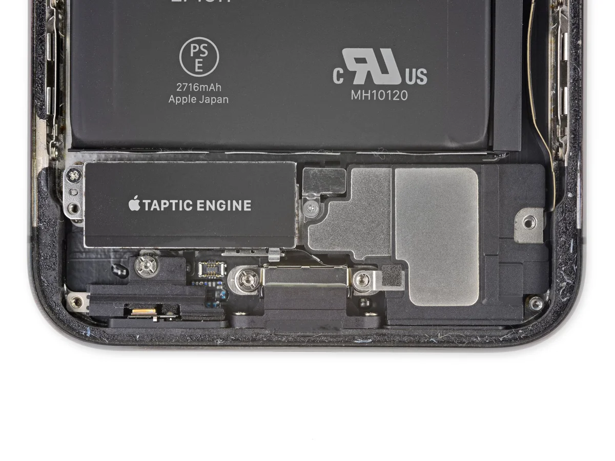
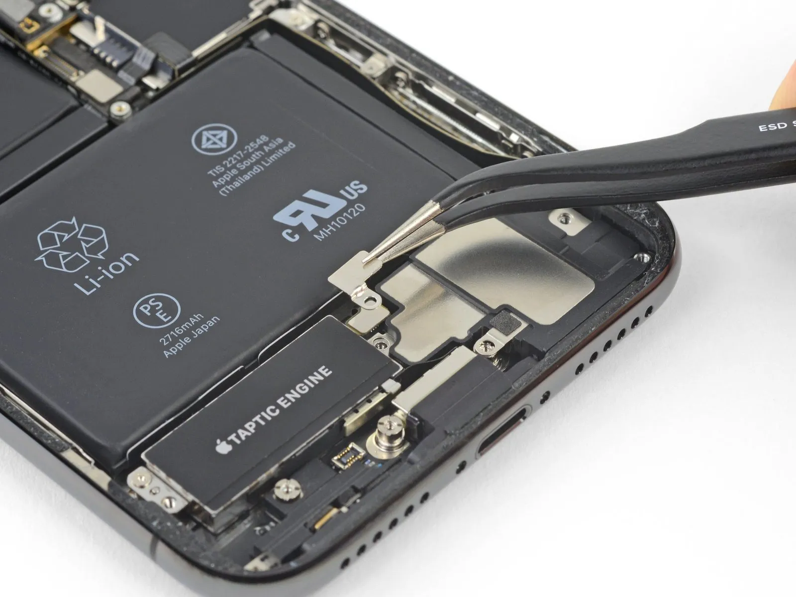
Step 38
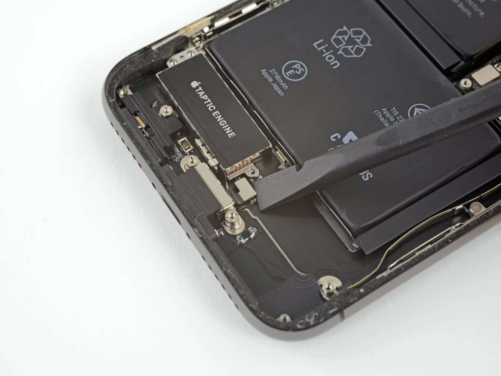
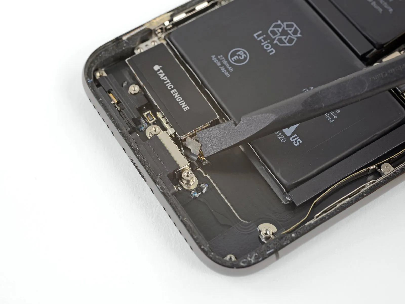
- Carefully detach the Taptic Engine flex cable from its connector by gently lifting it vertically with a spudger.
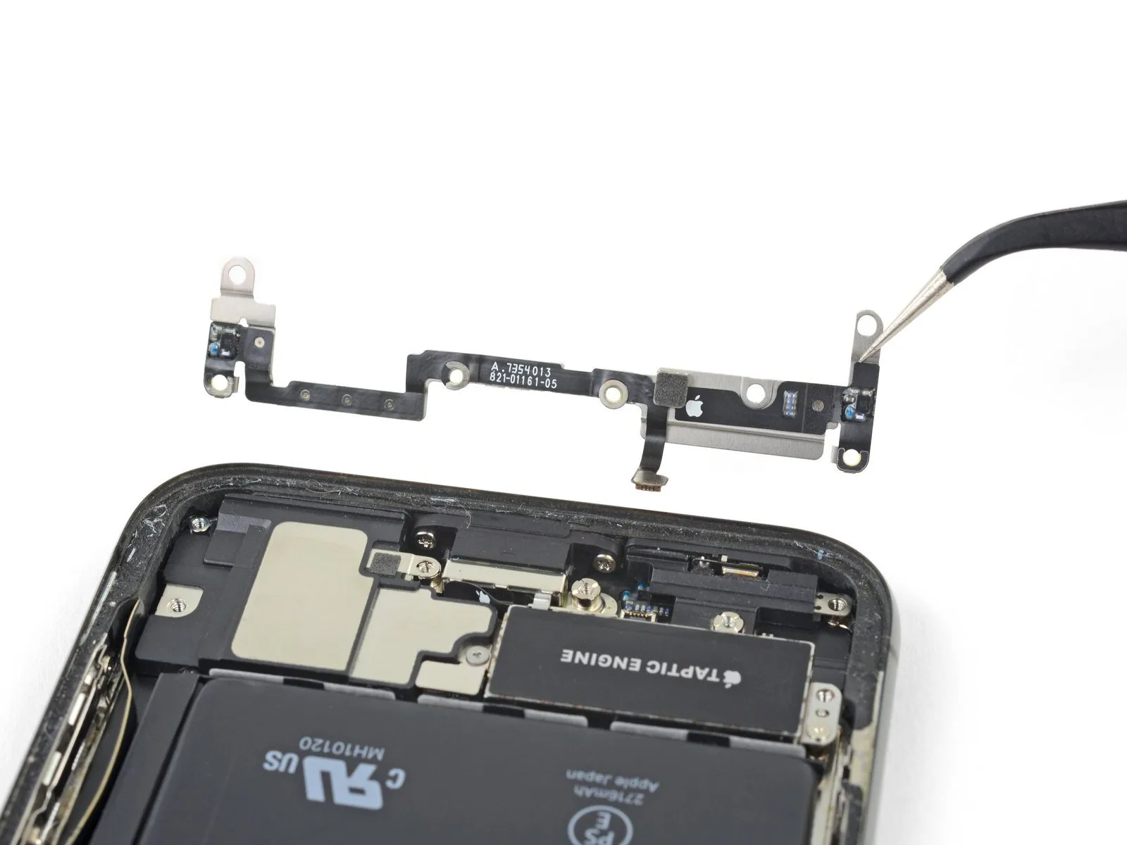
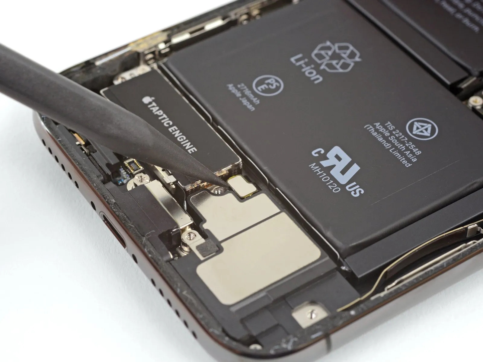
Step 39
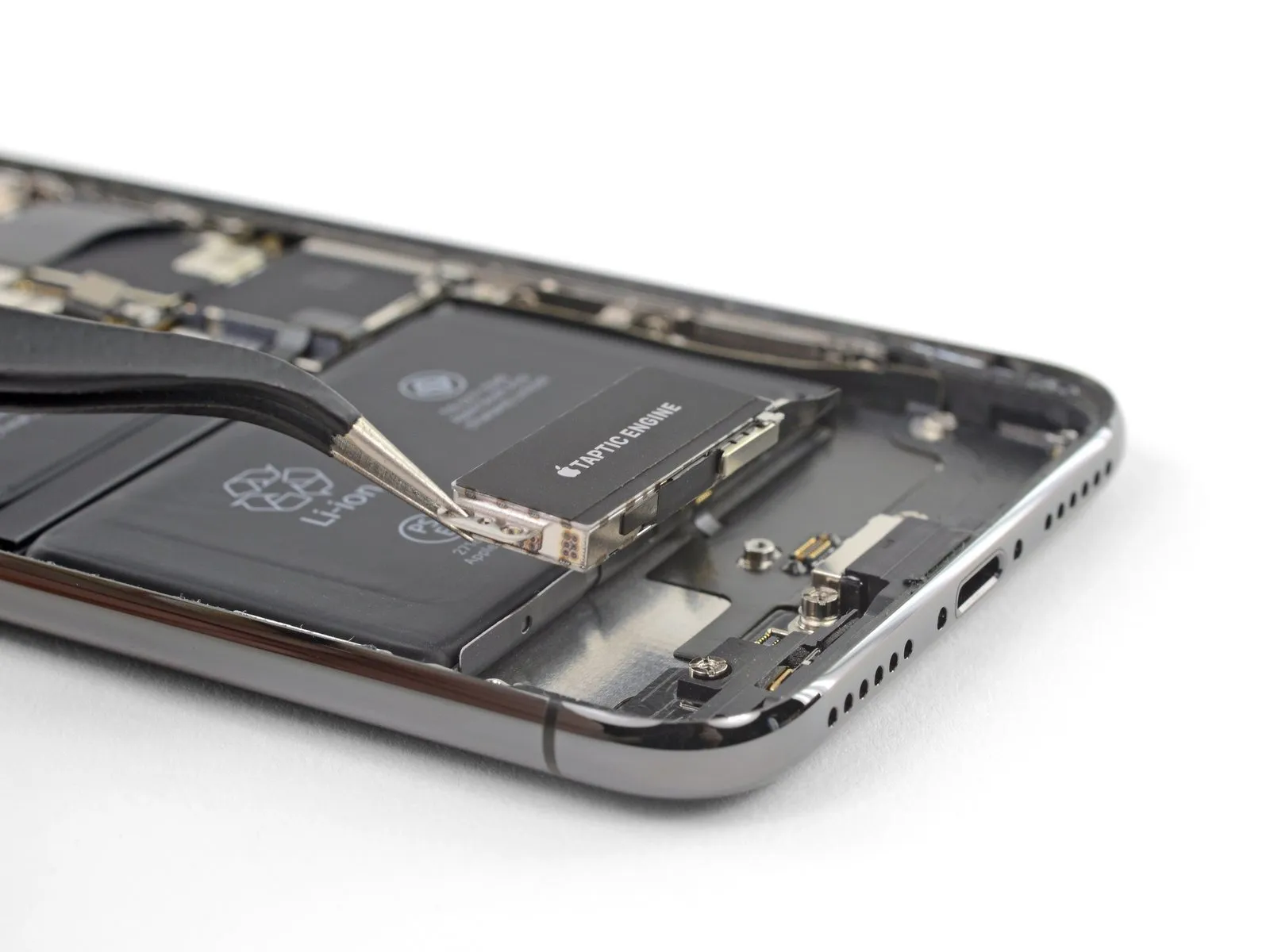
- Carefully detach the Taptic Engine, ensuring no damage occurs.
Step 40 | Battery
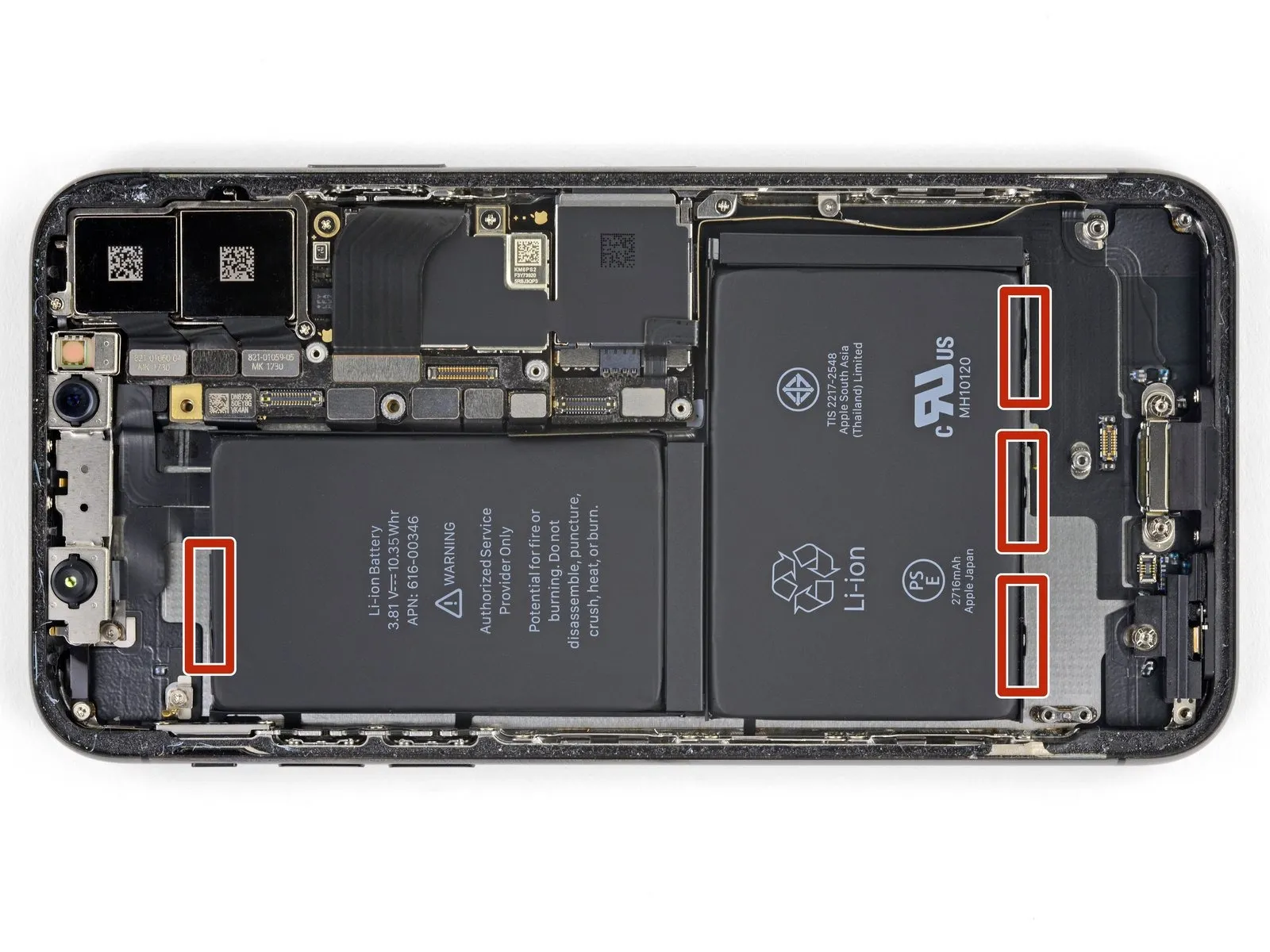
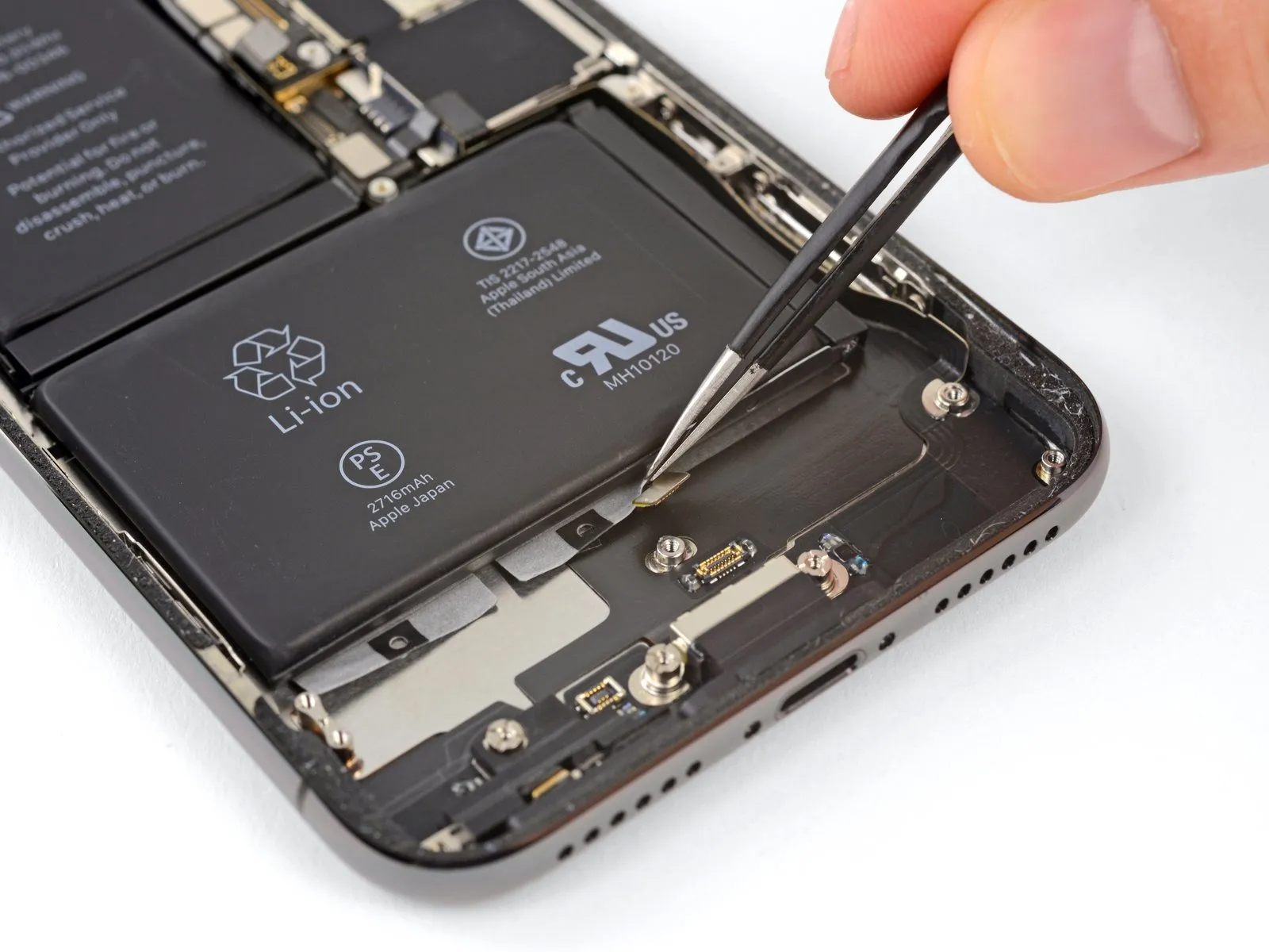
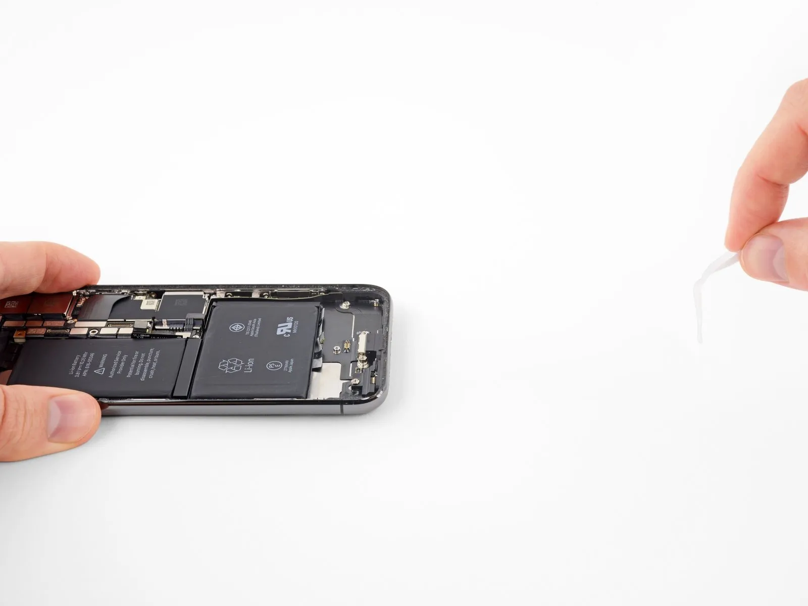
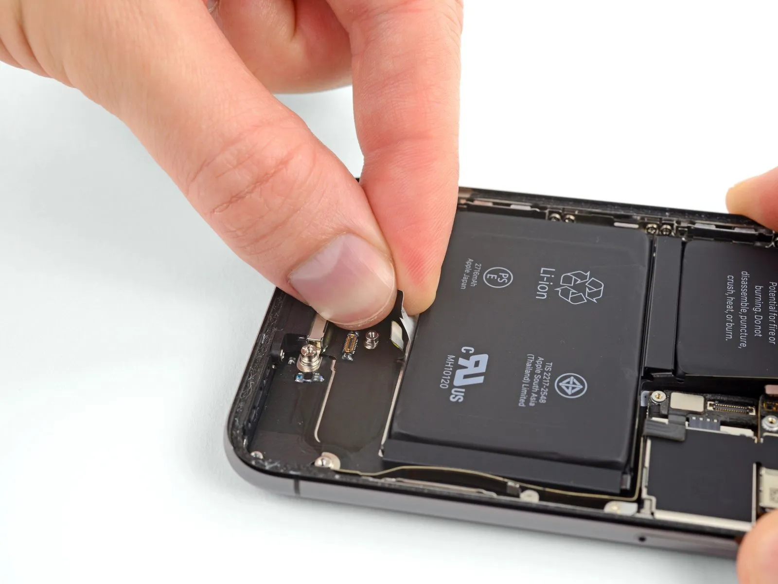
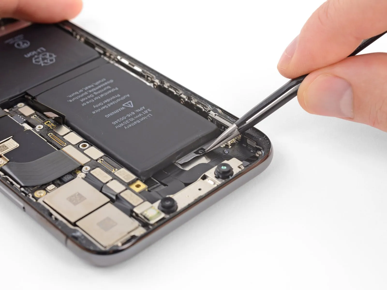
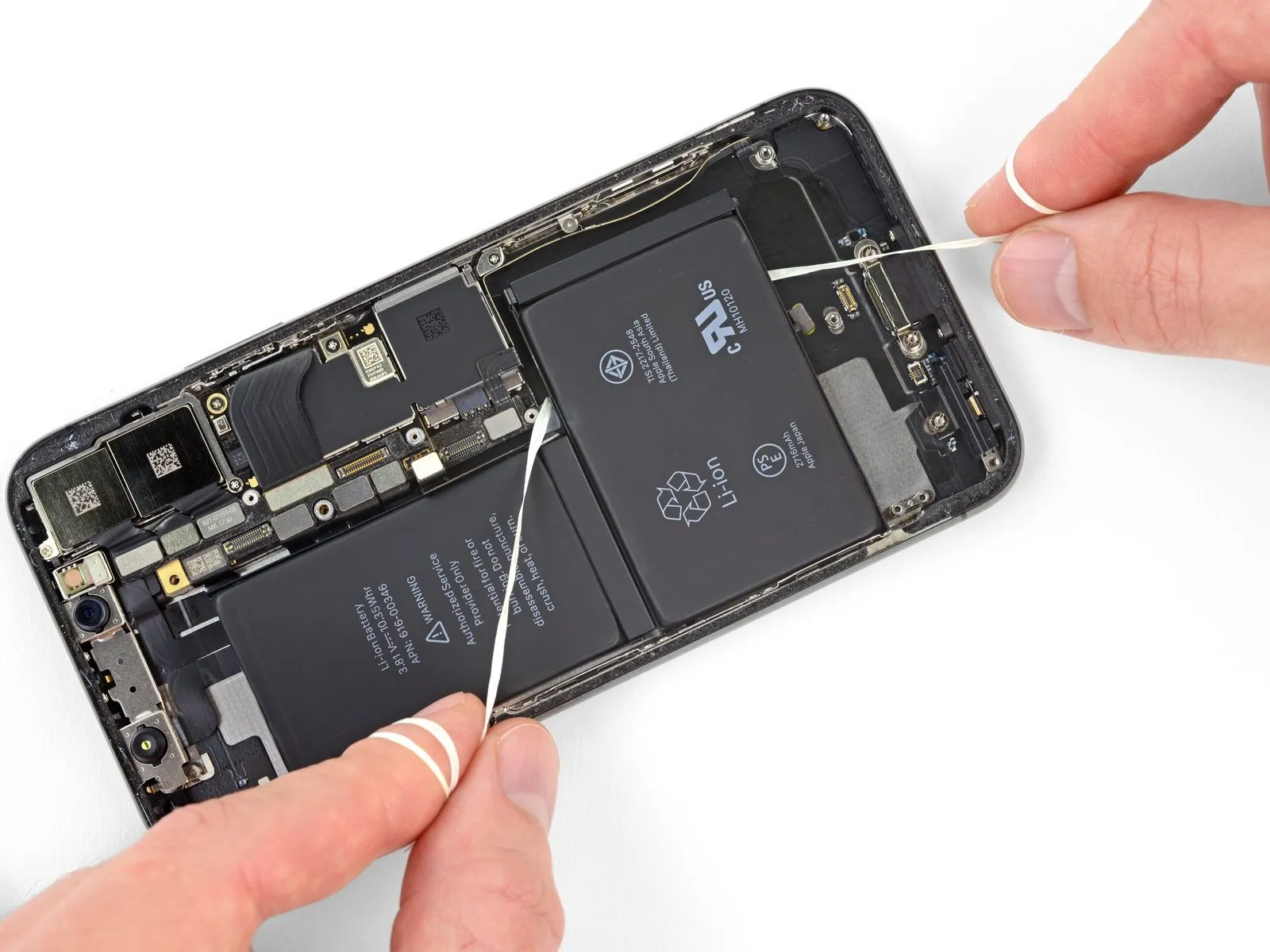
Four stretch-release adhesive strips hold the iPhone X battery in place; one secures the top cell, while three secure the bottom. Each adhesive strip features a black pull-tab lightly attached to the battery's side edge.
Step 41
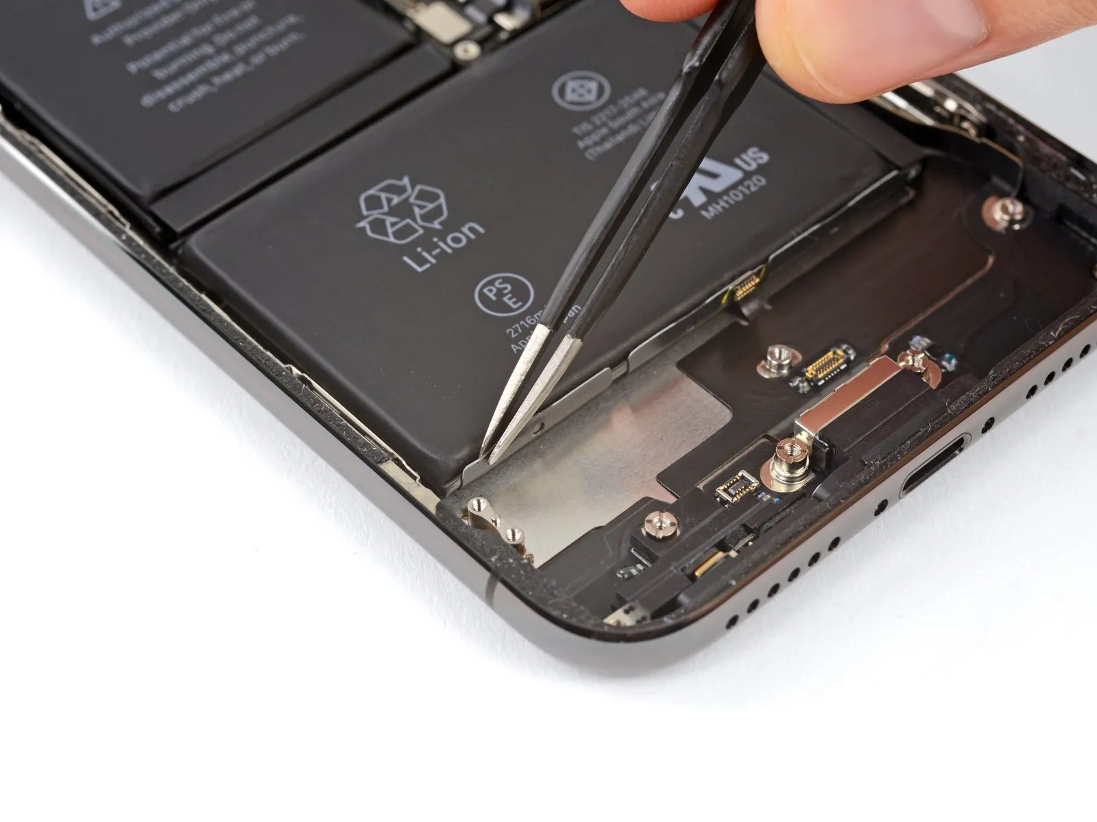
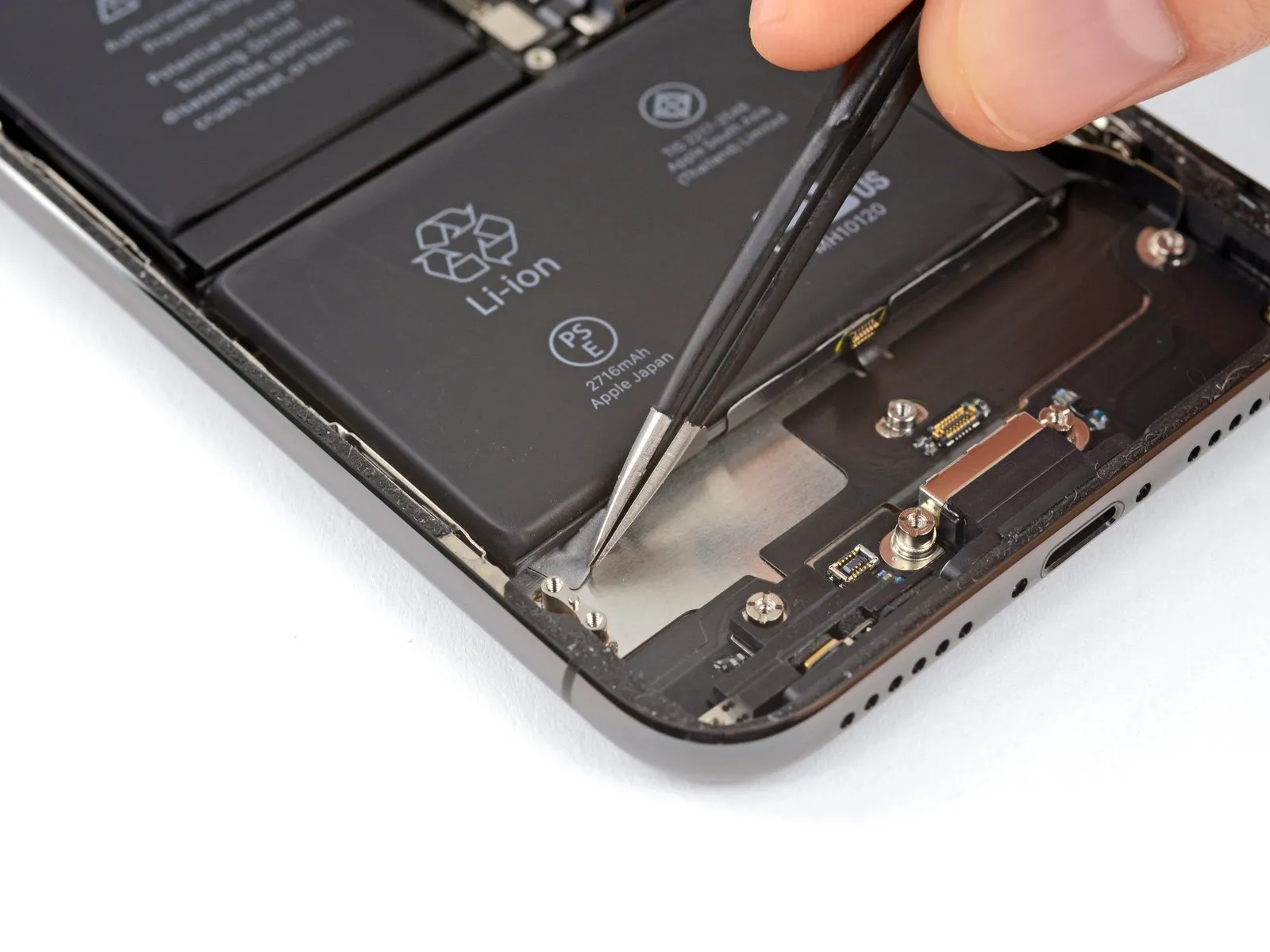
- Carefully detach the battery's adhesive tab from the lower edge.
- If the tab is difficult to grip directly, use a tool to access the small loop located centrally on each tab.
- Avoid piercing the battery using pointed implements, as damage could result in the release of hazardous chemicals or ignition.
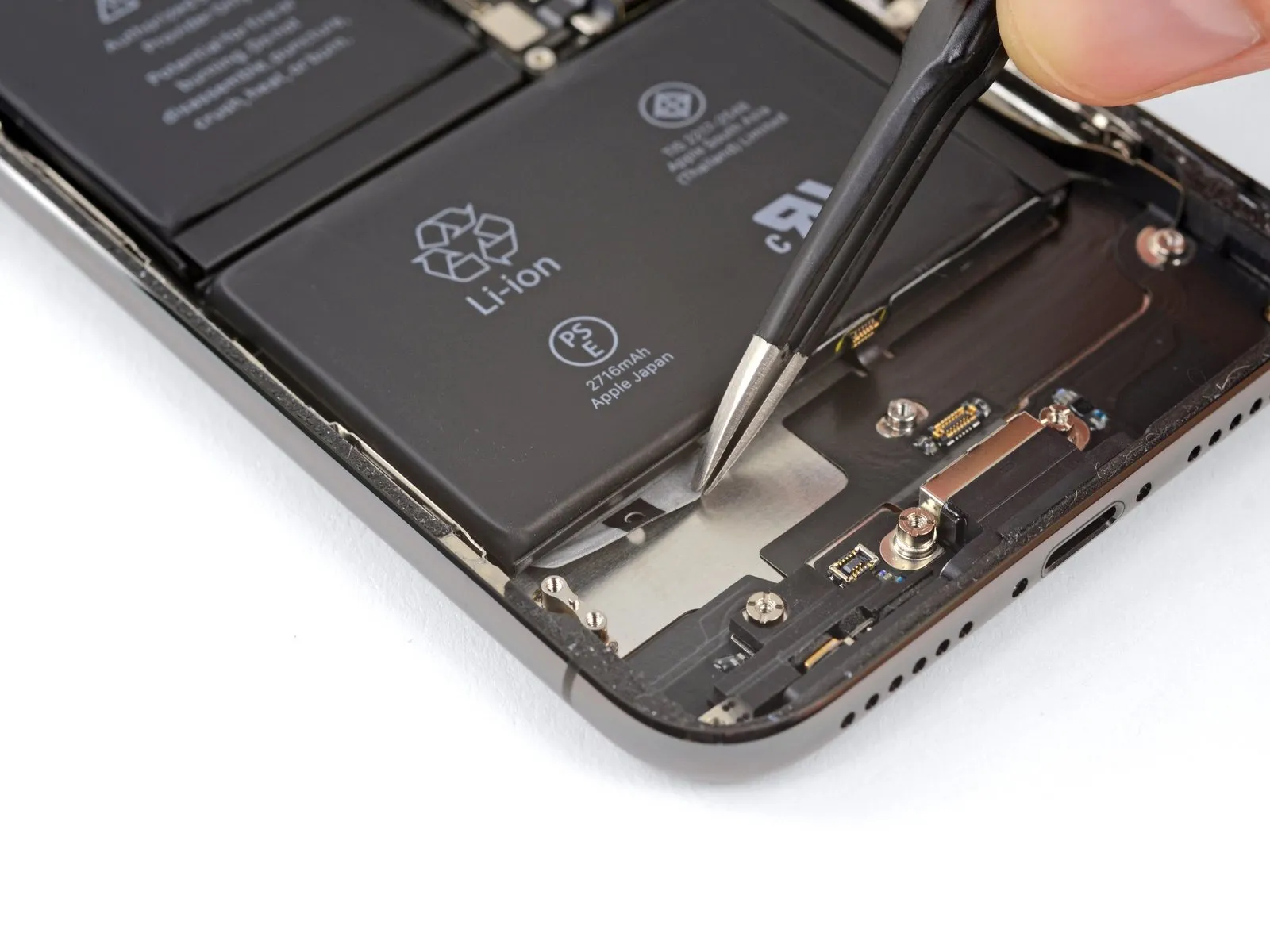
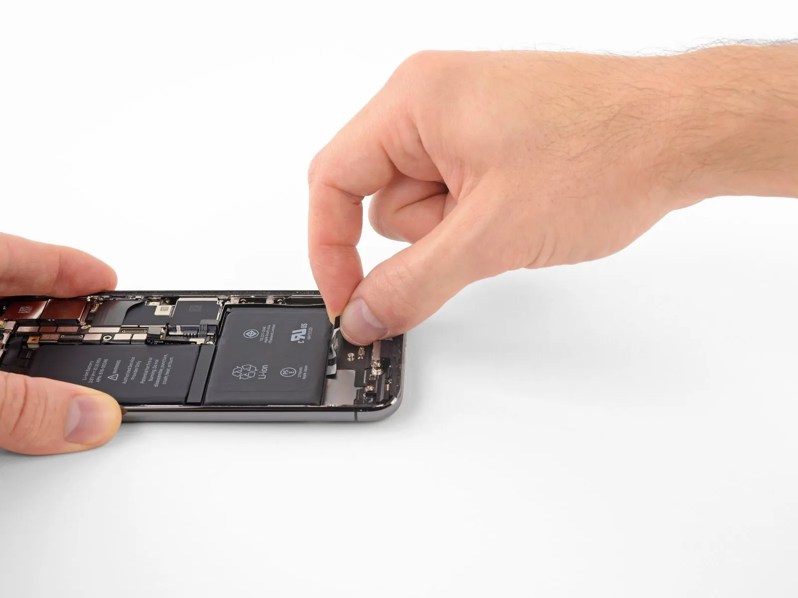
Step 42
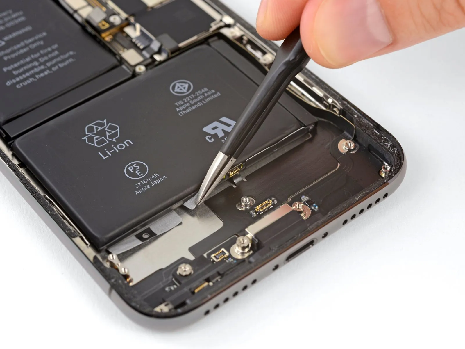
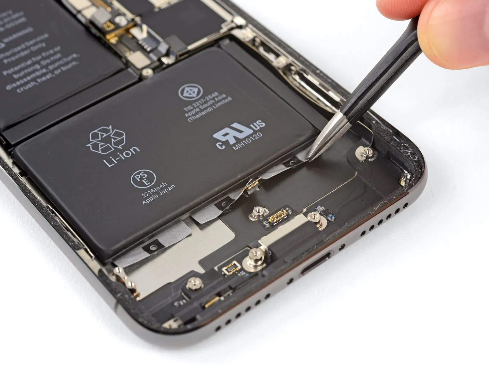
- Using the same technique, detach the two remaining adhesive tabs from the battery's lower edge.
- Exercise caution to avoid harming the speaker cable connector located immediately beneath the central adhesive tab.
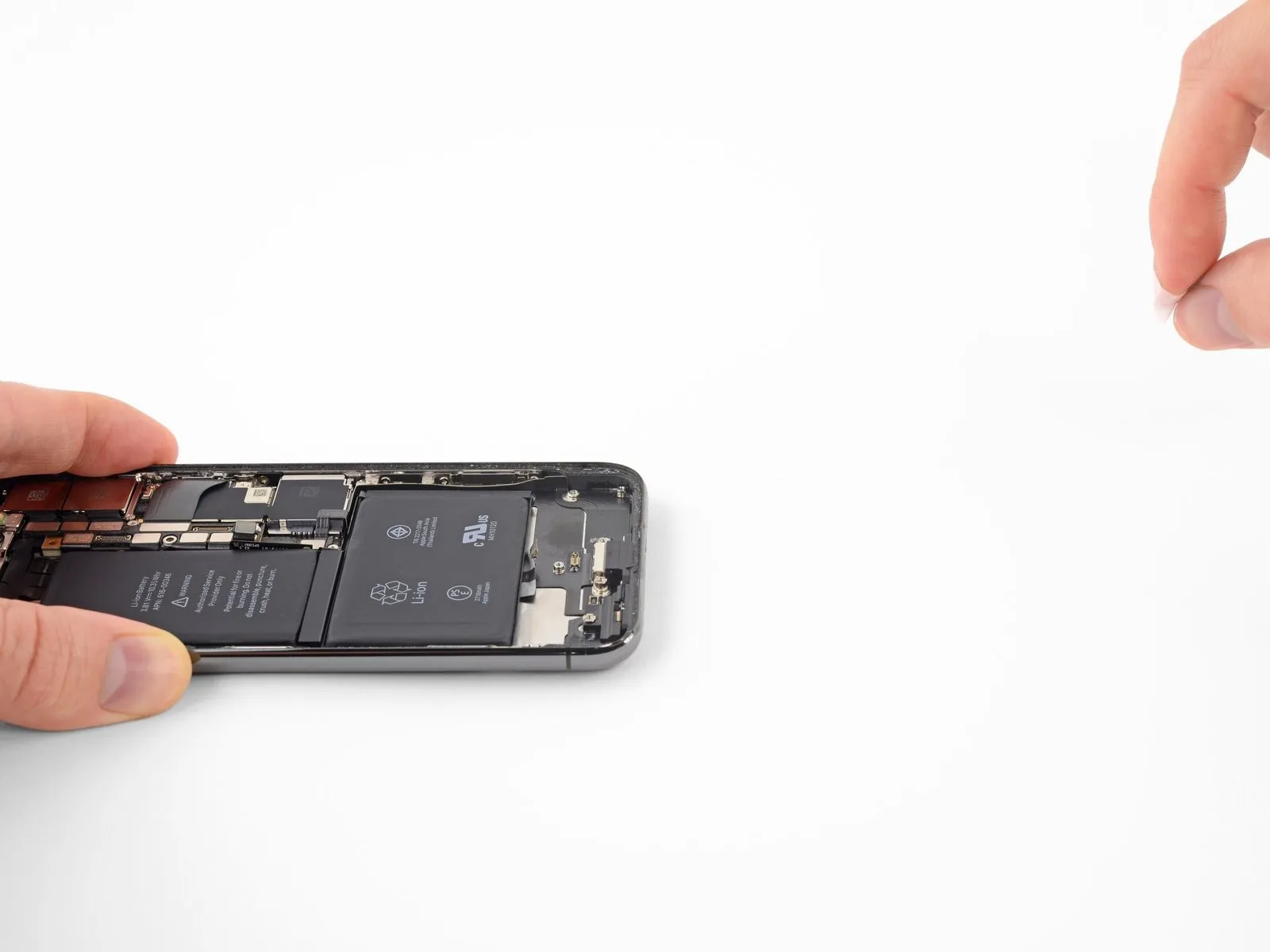
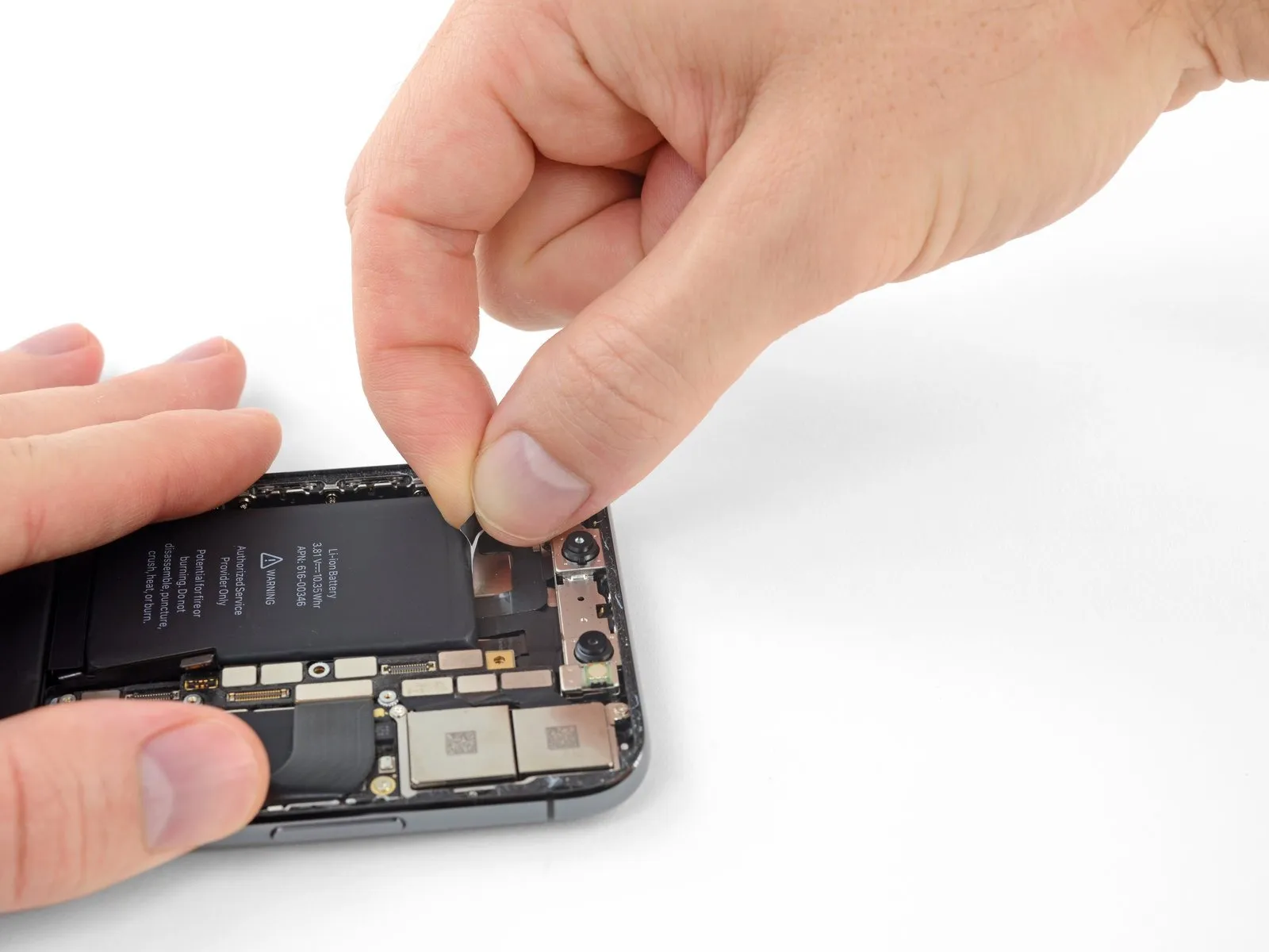
Step 43
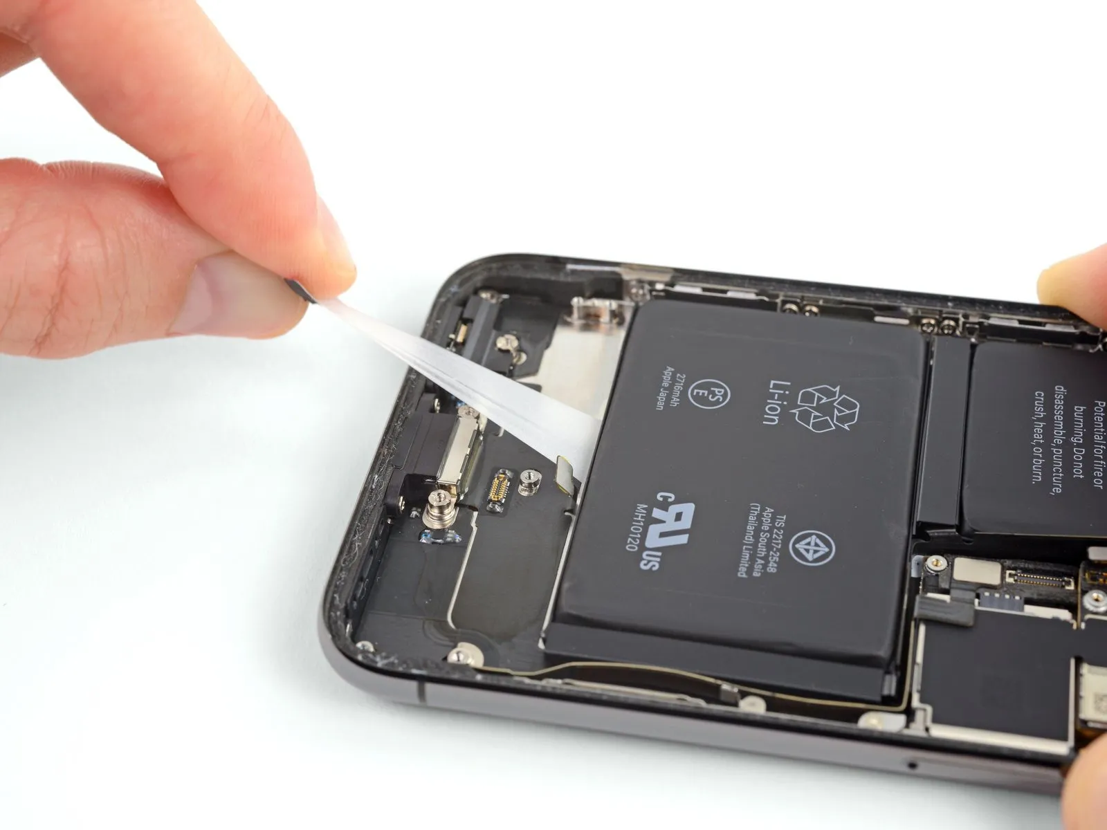
Gently separate the adhesive securing the battery by extending each tab, which will cause the underlying stretch-release adhesive to lose its grip and detach as a cohesive piece, facilitating battery removal.
Should the adhesive strips fracture, proceed calmly, as this is not an uncommon occurrence. Continue with the following instructions to properly remove the damaged strips.
Employing these practices will significantly improve the likelihood of a favorable outcome.
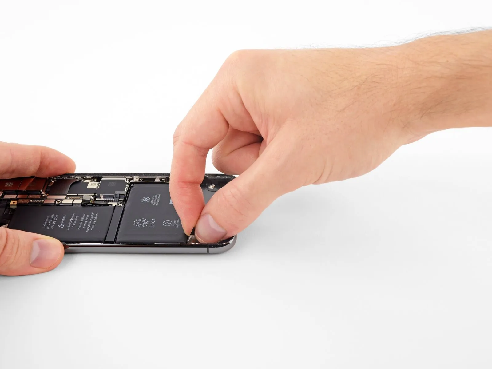
Avoid applying pressure to the battery; instead, maintain a secure grip on the iPhone's lateral edges.
Maintain a smooth, wrinkle-free condition of the strips while applying tension.
Apply gentle, gradual force, allowing approximately 15 to 30 seconds for each strip to extend and detach.
To prevent the strip from catching on the battery's lower edge, exert a pulling force at a shallow angle.
Should a strip fracture and become inaccessible beneath the battery, proceed to the remaining strips and then follow the subsequent instructions.
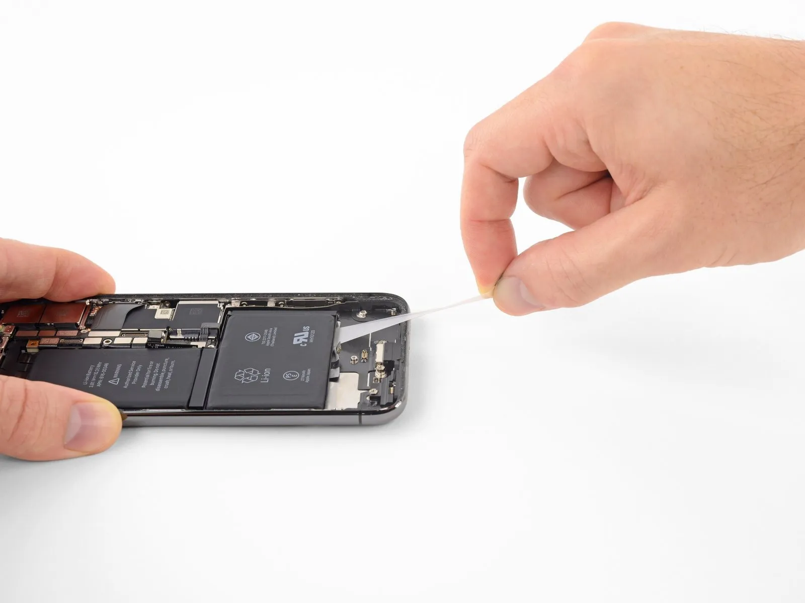
Step 44
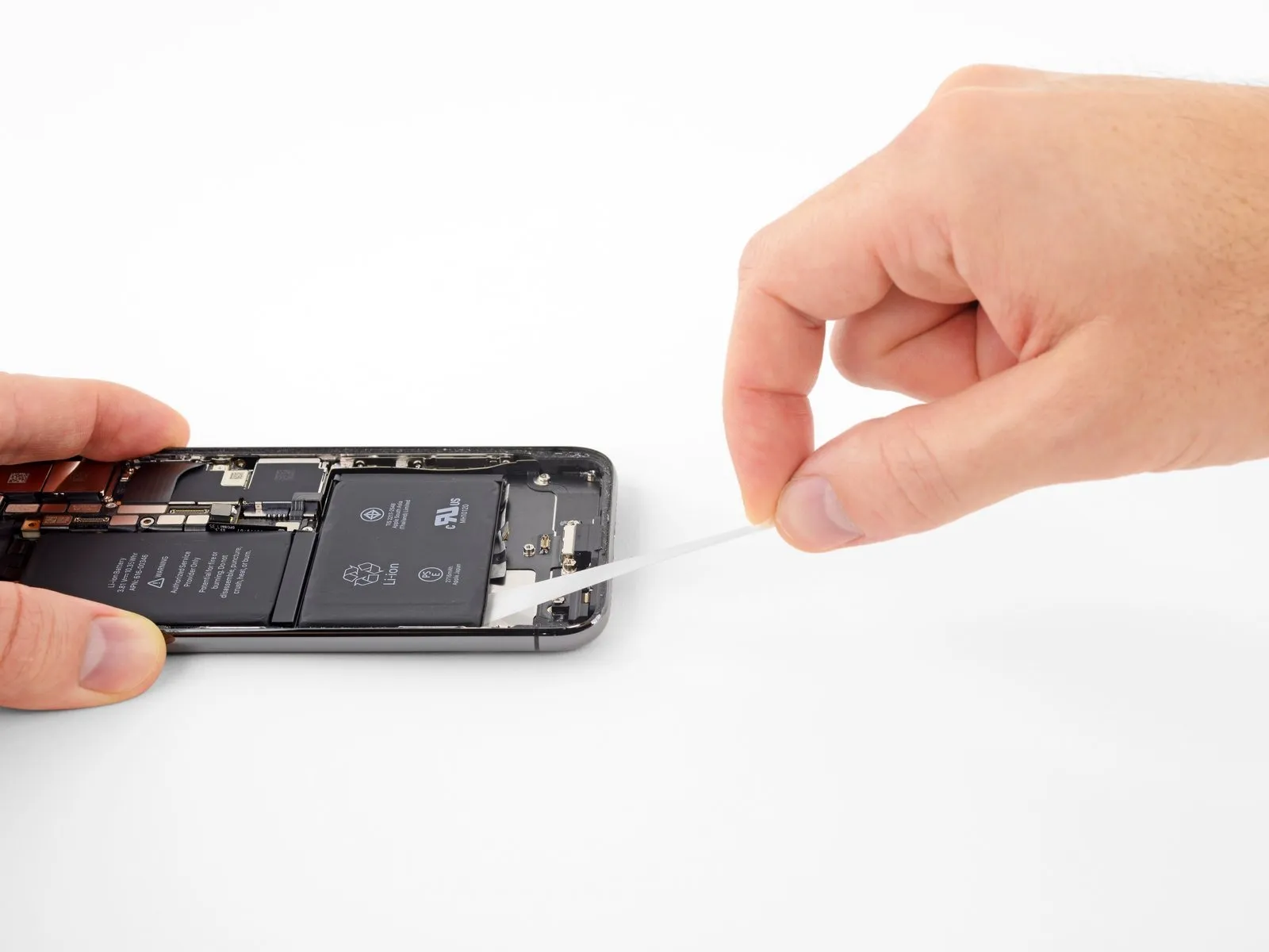
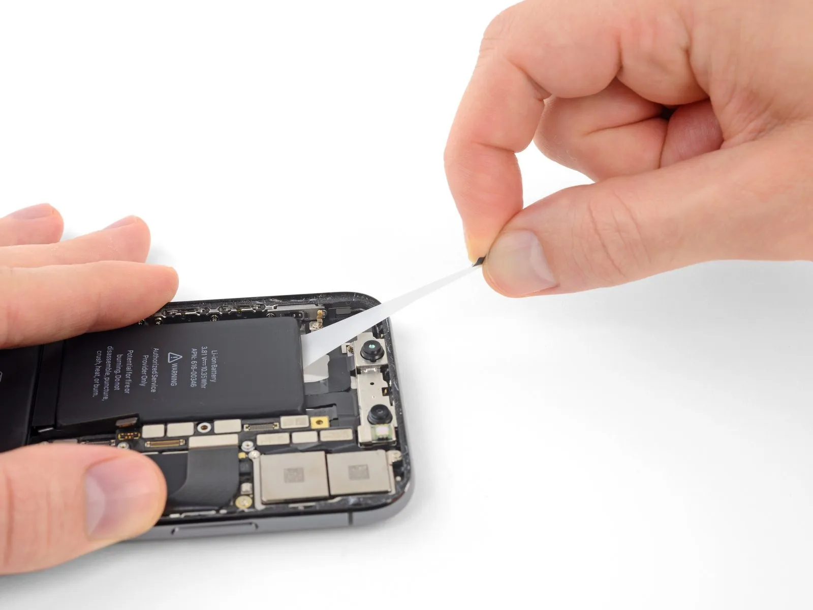
- Gently separate one of the battery's adhesive strips, drawing it downwards along the iPhone's base.
- Apply consistent, even force to the strip, ensuring continuous pressure as it disengages from the space between the battery and the rear case.
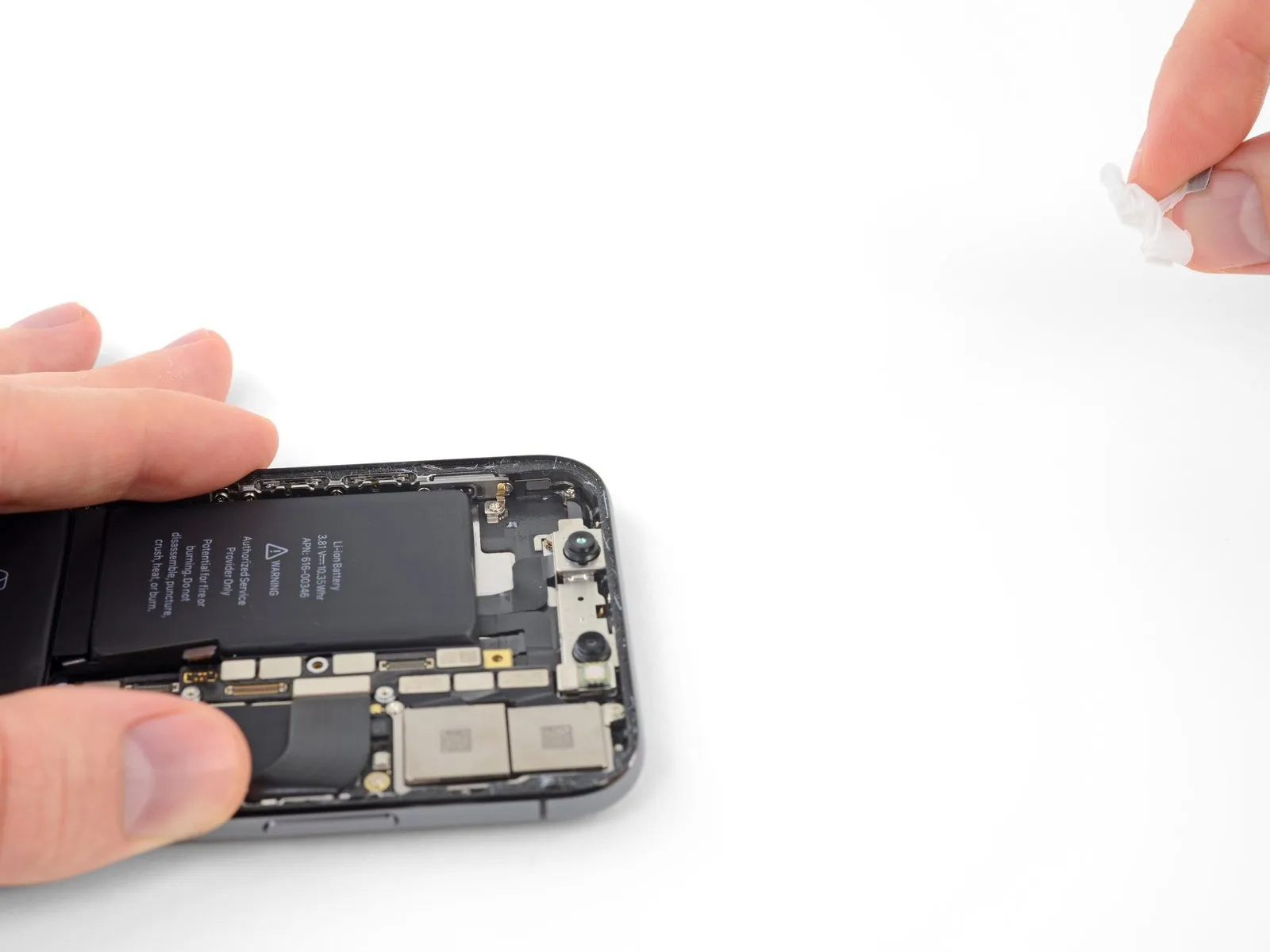
- Expect the strip to extend significantly, potentially several times its initial measurement. To maintain tension and progress, reposition your grip closer to the battery as needed while continuing to pull.
- Should the battery's adhesive strips tear apart while removing it, carefully extract any detached adhesive fragments using your fingers or a tool with a rounded, non-sharp tip, then proceed with the removal.
- Should the adhesive securing the battery tear or become inaccessible during removal, carefully detach any visible portions of the strips and continue with the subsequent steps.
Step 45
Step 46
- Carefully detach the central section.
Step 47
- Carefully inspect the Face ID components, as the final pull tab is situated in immediate proximity and any damage to it could affect functionality.Apple is the sole authorized provider for Face ID repairs.Exercise caution during this procedure.
- Carefully remove the protective pull tab from the adhesive strip, which is positioned along the top edge of the upper battery cell.
Step 48
- Carefully detach and discard the last strip of adhesive.
- To prevent the battery from being ejected during separation of the strip from the iPhone, position your hand above it for stability; however, avoid applying direct pressure to the battery's surface, as this could damage the underlying adhesive strip.
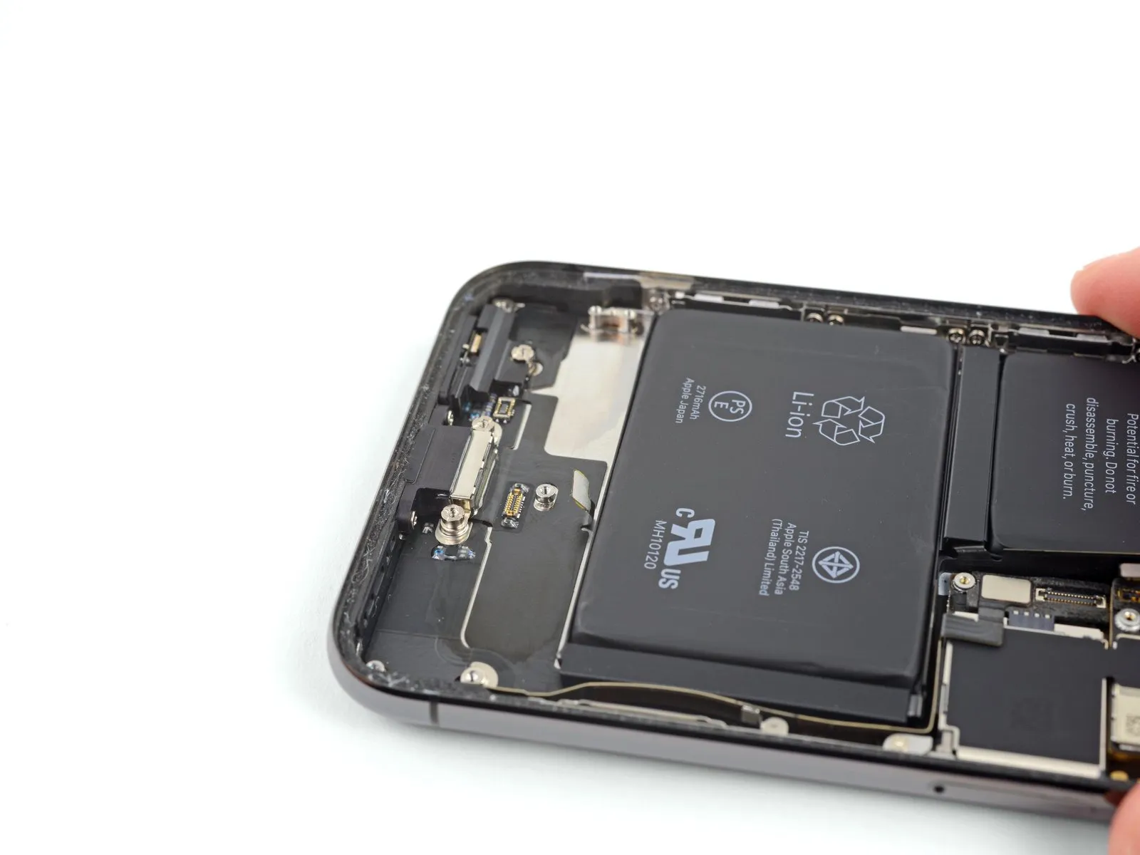
- Having detached all four adhesive strips without issue, proceed to the subsequent instruction.
- To reattach a detached battery adhesive, carefully dispense a small quantity—several drops—of adhesive directly beneath the battery.Isopropyl alcohol with a purity exceeding 90% is required.Locate the battery's lower edge, specifically the region where the damaged adhesive strip(s) are situated.
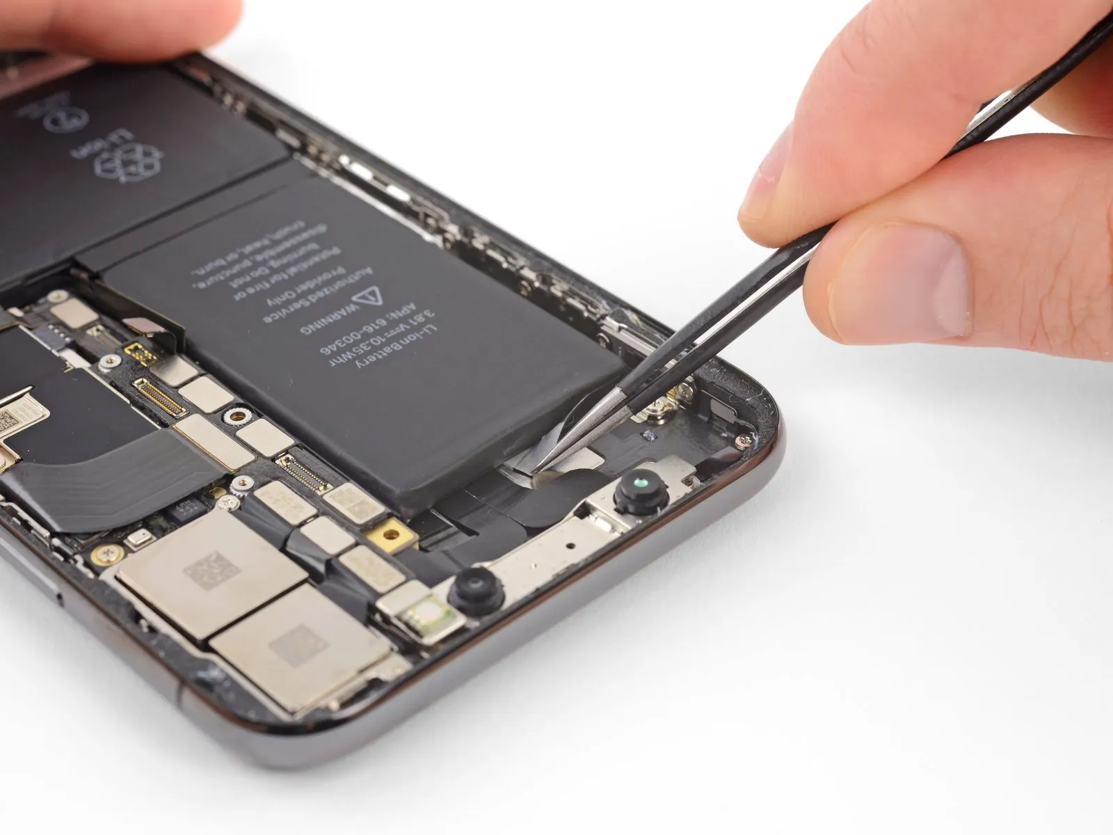
- Allow approximately one minute for the alcohol to dissolve the adhesive securing the battery, then carefully separate the battery from the device casing using the spudger's flat edge.
- To prevent damage, avoid using excessive force when removing the battery. Should the battery remain stuck, add additional alcohol to dissolve more of the adhesive. Ensure the pry tool does not damage or penetrate the battery's casing during the release process.
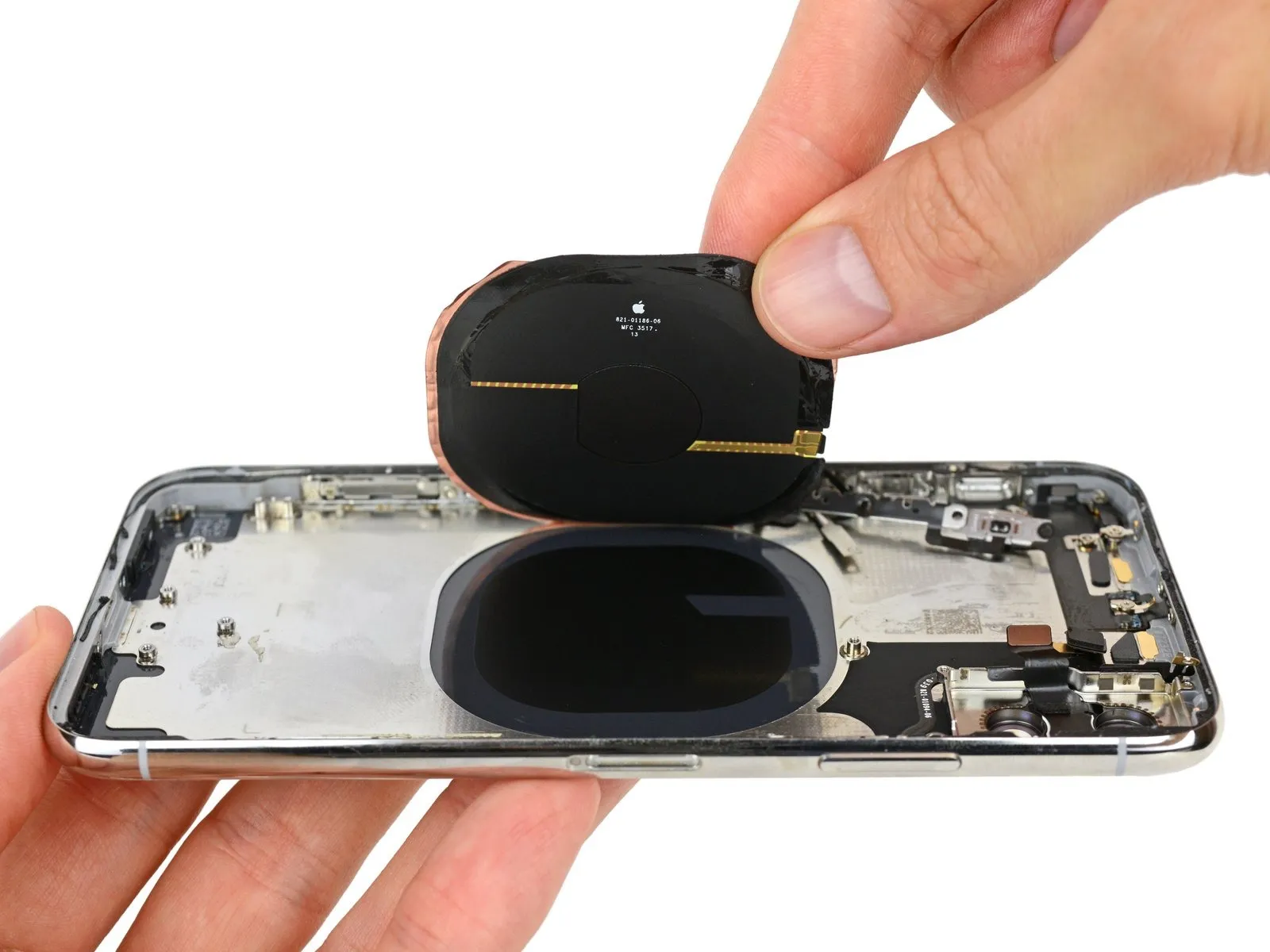
- Exercise caution to prevent harm to the flexible ribbon cables and the wireless charging coil located immediately beneath the battery.
Step 49 | Alternative method to unstick the battery from the case
- To detach a battery adhered to the rear case when adhesive strips are damaged, apply heat to the case's rear surface, positioned directly behind the battery, using either an iOpener or a hair dryer.
- Apply warmth to the iPhone's back surface, ensuring it reaches a temperature just beyond comfortable skin contact; avoid excessive heat to prevent battery ignition.
- Carefully turn the iPhone over, then slide a durable string—like dental floss or a similarly thin guitar string—beneath the battery.
- To safeguard your fingers from potential abrasion, use a piece of fabric to cover the string ends, or alternatively, wear gloves.
- Using a back-and-forth, sawing movement, gently work the string along the entire length of the battery to release the adhesive bond. The adhesive requires careful manipulation and may take a while to loosen, so exercise patience to avoid stressing the battery. Prevent any physical damage or distortion to the battery itself.
- Exercise significant care when employing prying implements to release the battery, as underlying ribbon cables and the wireless charging coil are susceptible to damage.
Step 50
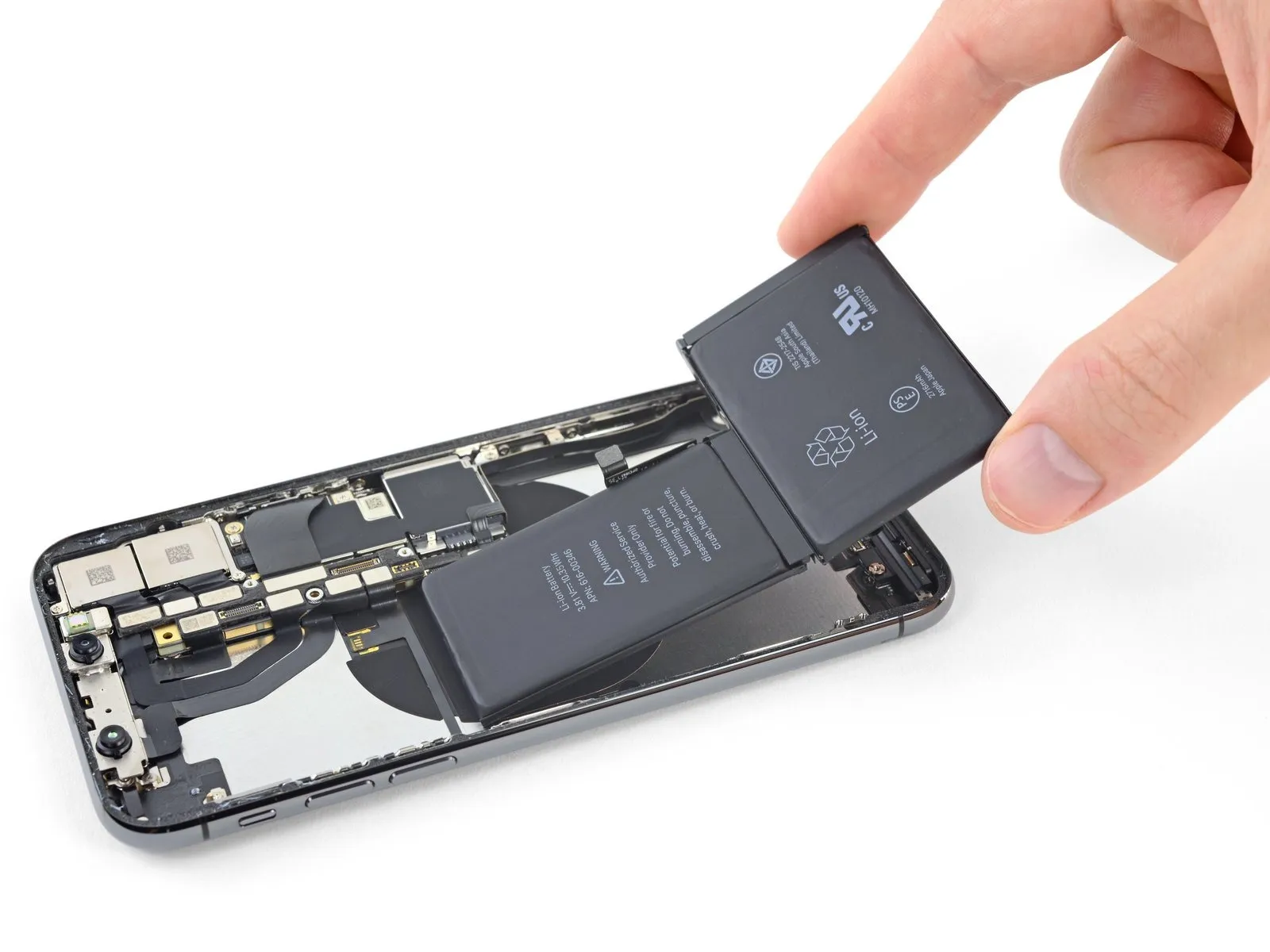
- Using a firm grip, lift the battery upwards from its lower edge to detach it from the iPhone.
- To prevent damage, ensure any residual alcohol solution is completely removed by wiping with a clean cloth or by permitting it to evaporate fully prior to battery installation.
- To ensure proper battery alignment during replacement, first reattach the Taptic Engine and speaker components.
- To confirm correct positioning within its designated space, briefly plug the battery connector back into the logic board's socket prior to securing the new battery.
- Secure the battery in place, then sever its electrical connection before proceeding with the remaining assembly steps.
- To secure a battery lacking factory-applied adhesive, follow the instructions in this guide for adhesive strip replacement.
- Following reassembly, execute a forced restart to proactively resolve potential problems and streamline any subsequent diagnostic procedures.
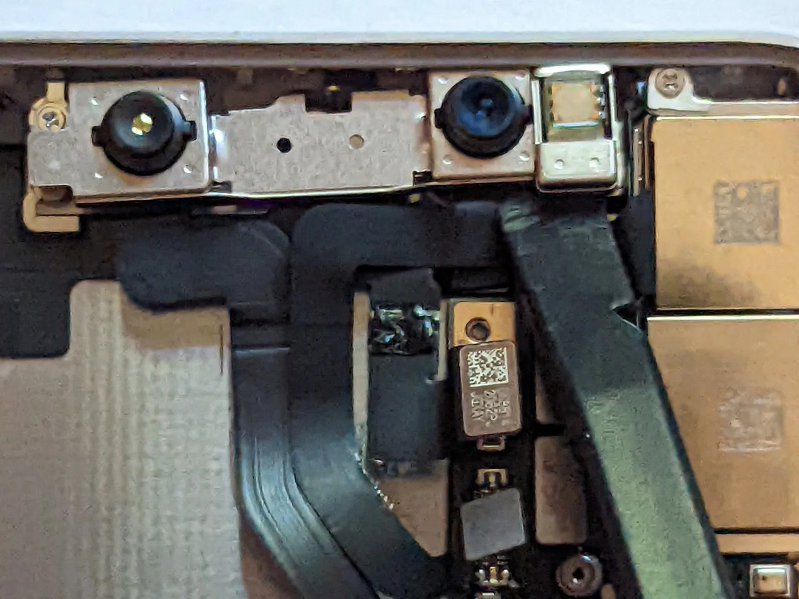
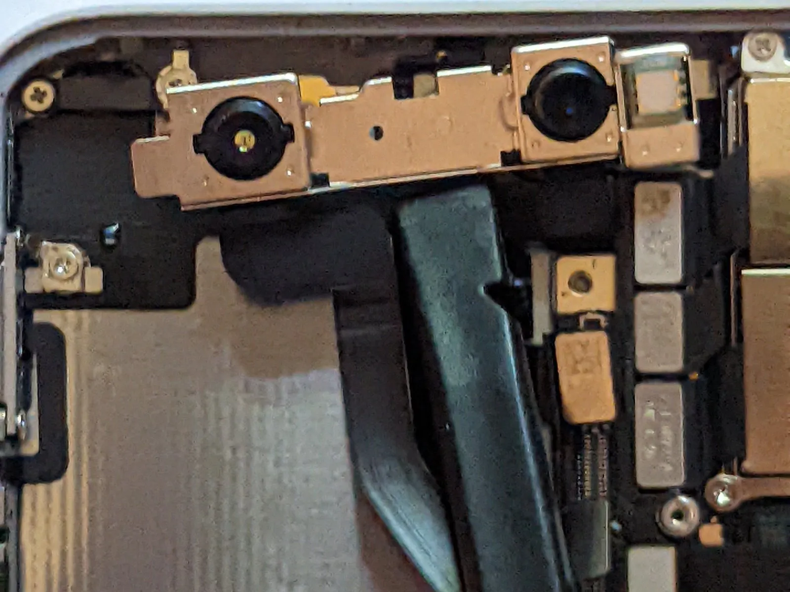
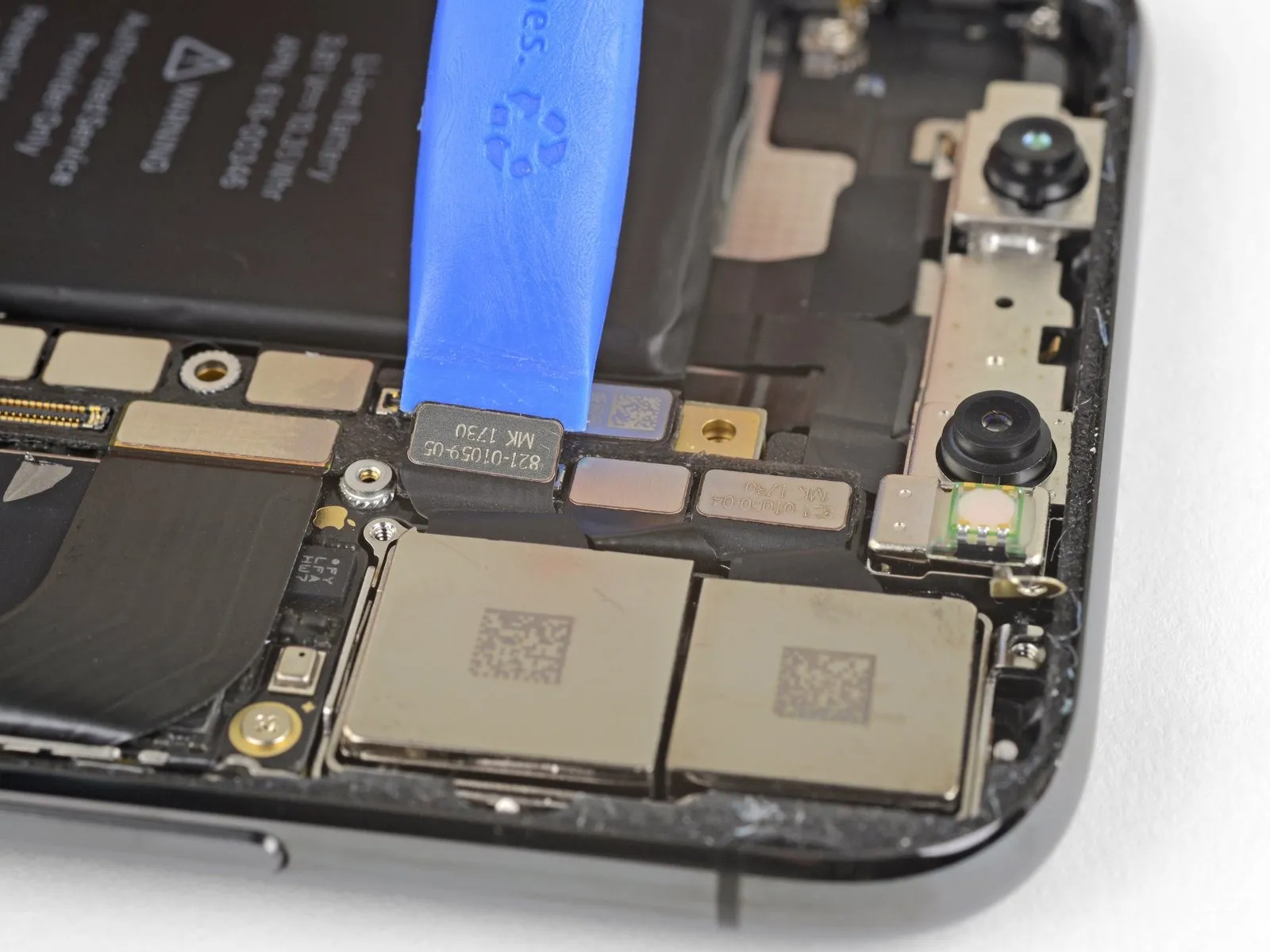
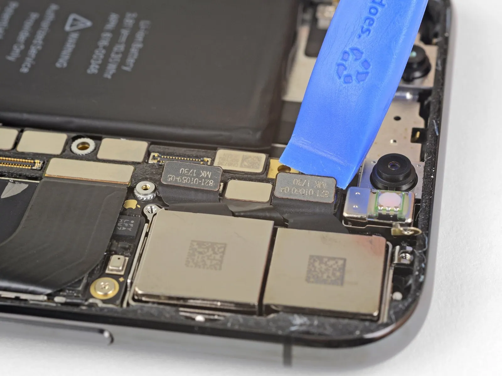
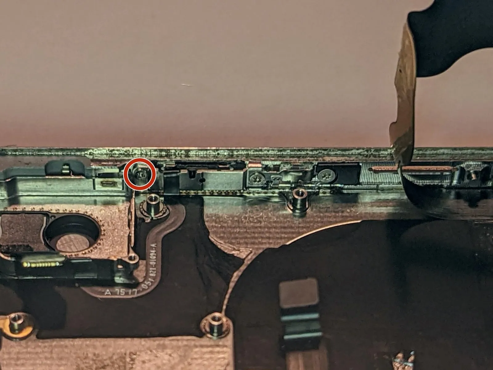
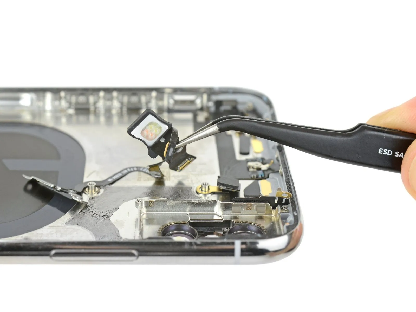
Step 51 | Front Camera Assembly


- Carefully separate the three front camera assembly connectors from their sockets using the flat spudger.
Employ the provided projector to display a reference point.
The camera module located on the device's front face.
Utilize the provided infrared camera.
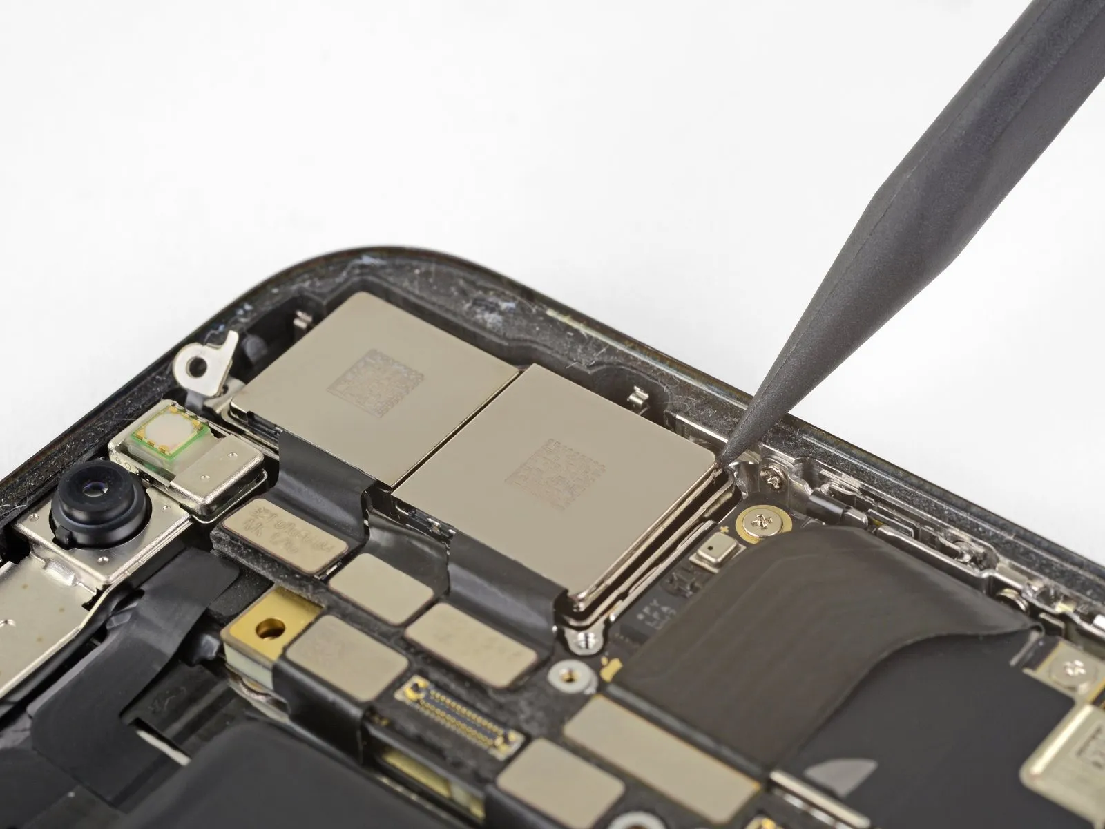
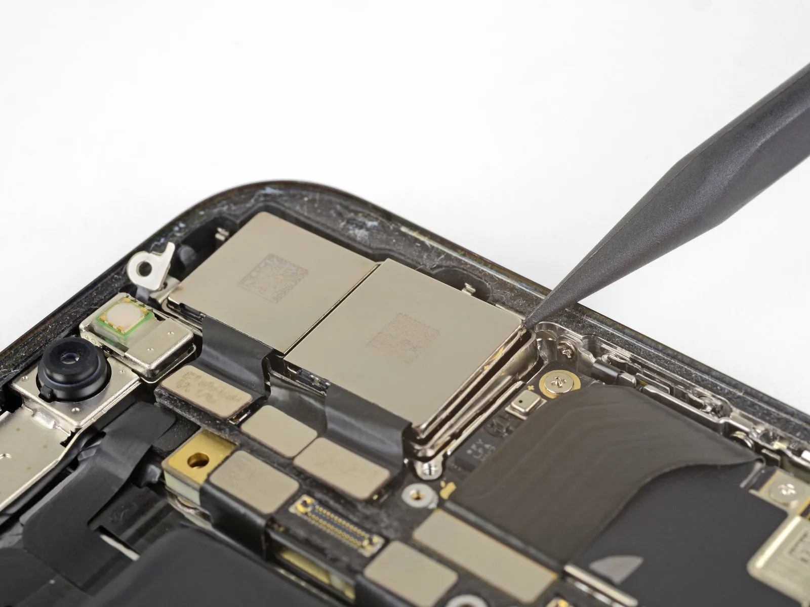
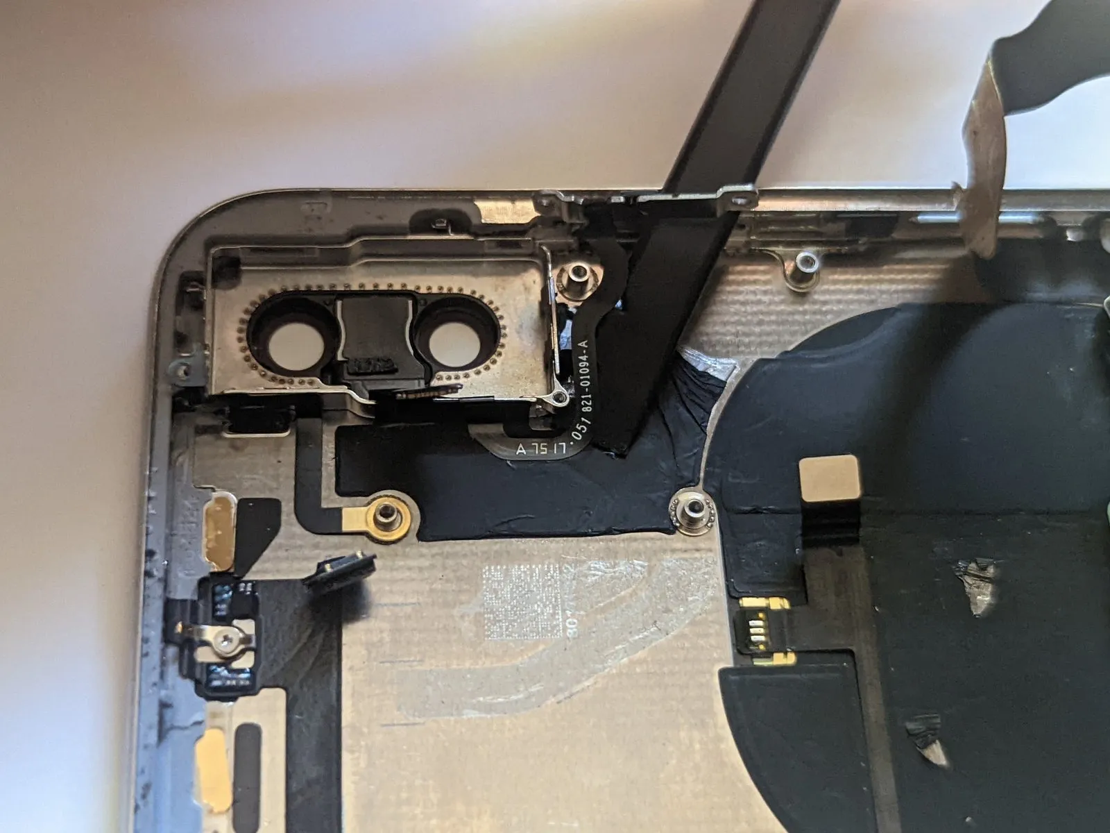
Step 52
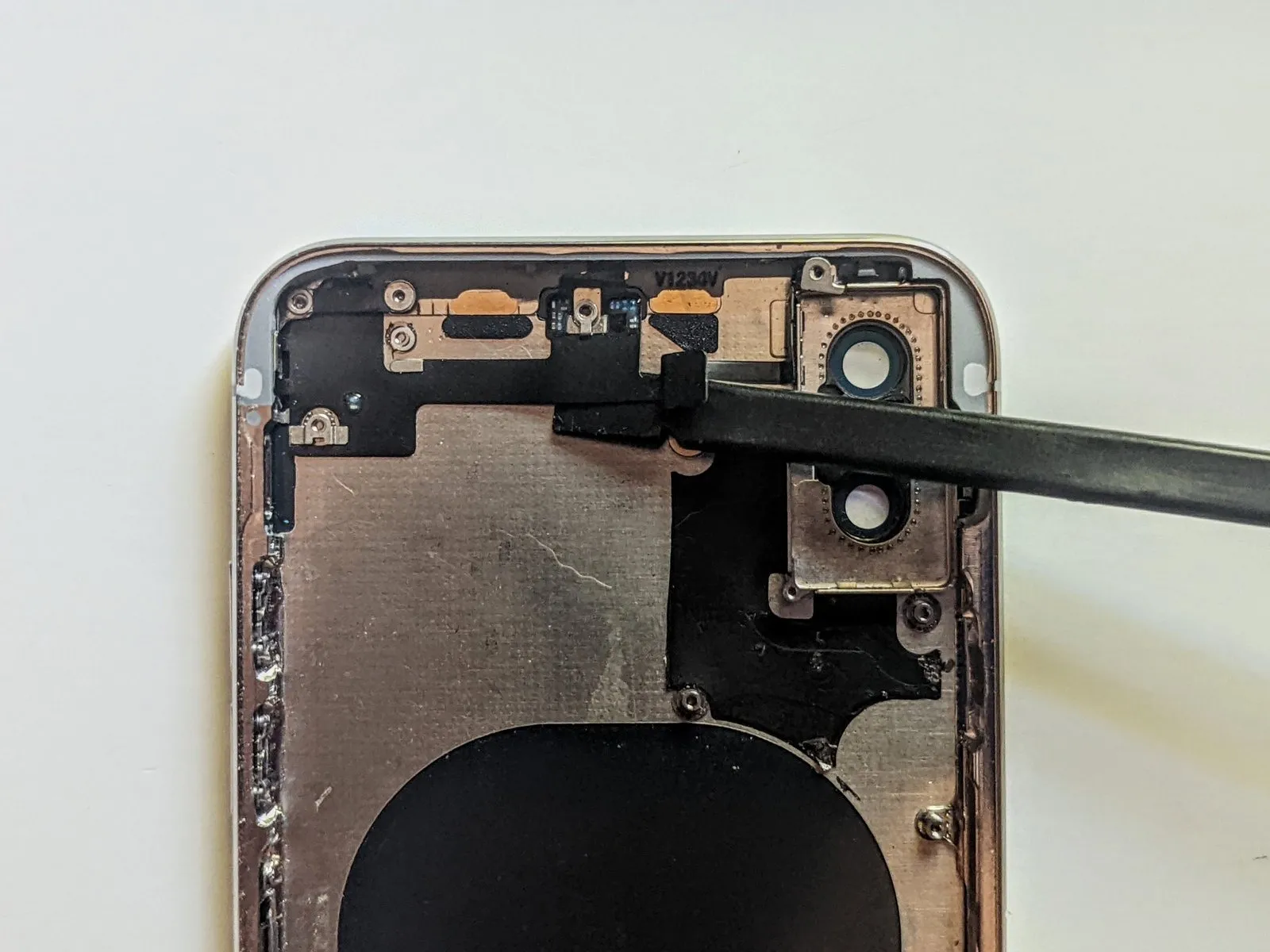
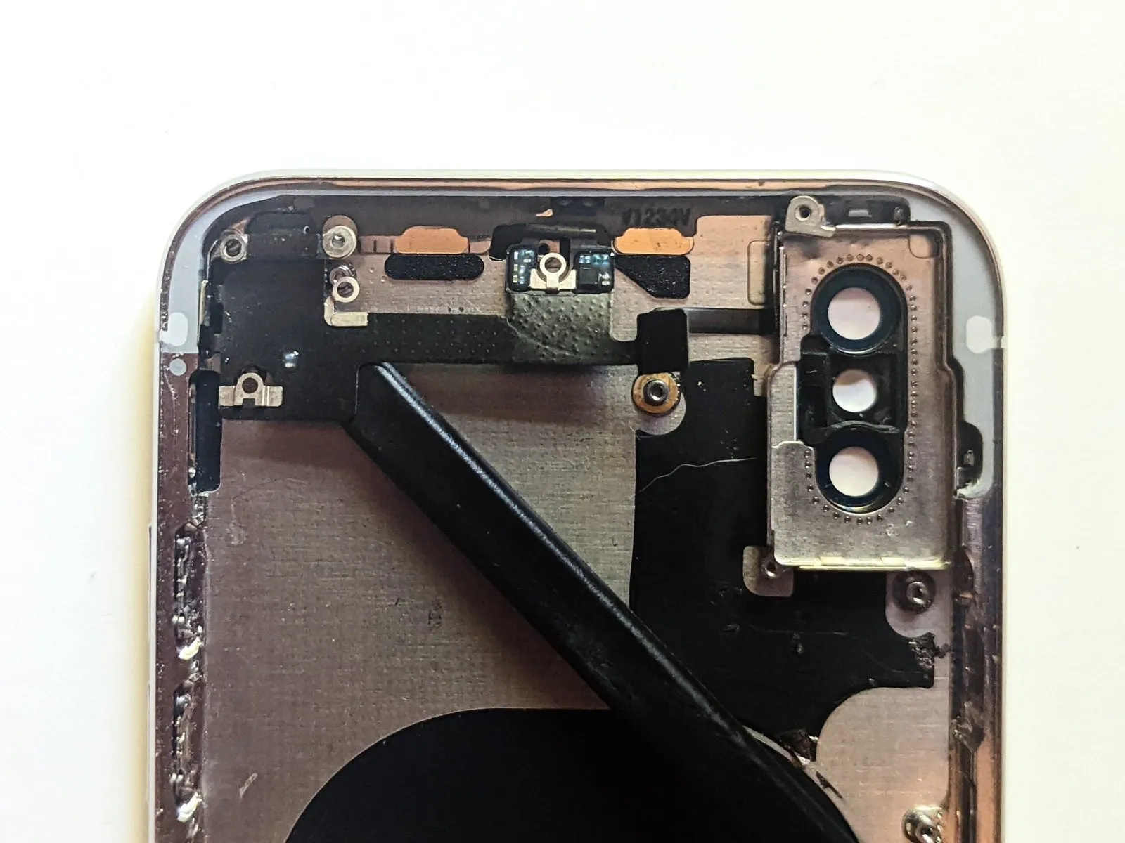
Use gentle pressure to position the camera cables, as they are secured to the midframe with a mild adhesive.
Carefully insert the spudger tip, beginning at the connector, and gently slide it between the infrared camera cable and the device casing to release the cable.
Perform the same procedure on the front camera cable.
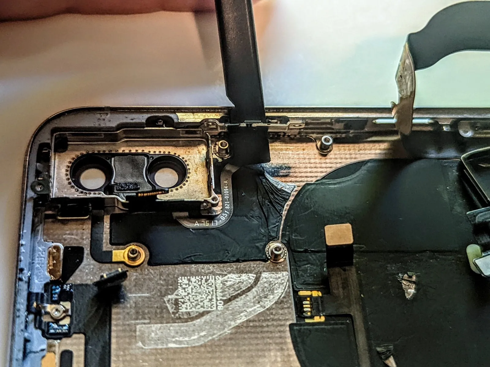
Step 53
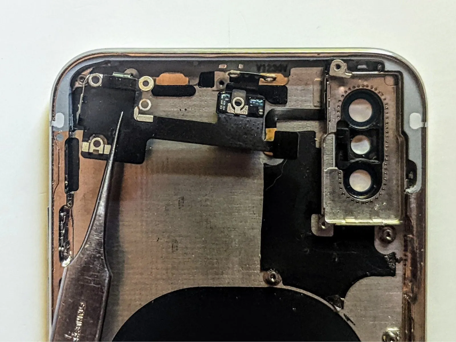
Use heat to soften the adhesive securing the front camera assembly.
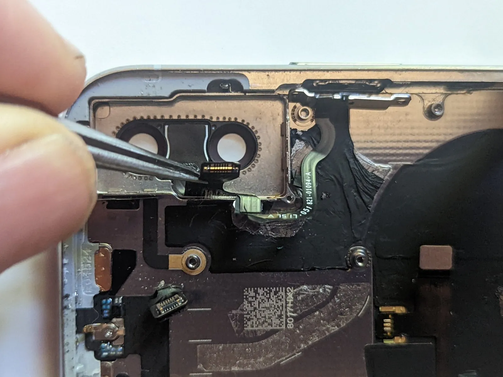
Step 54
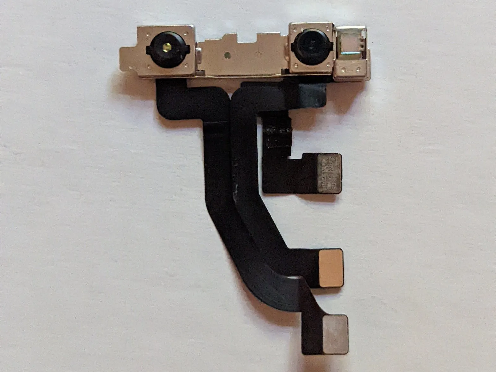
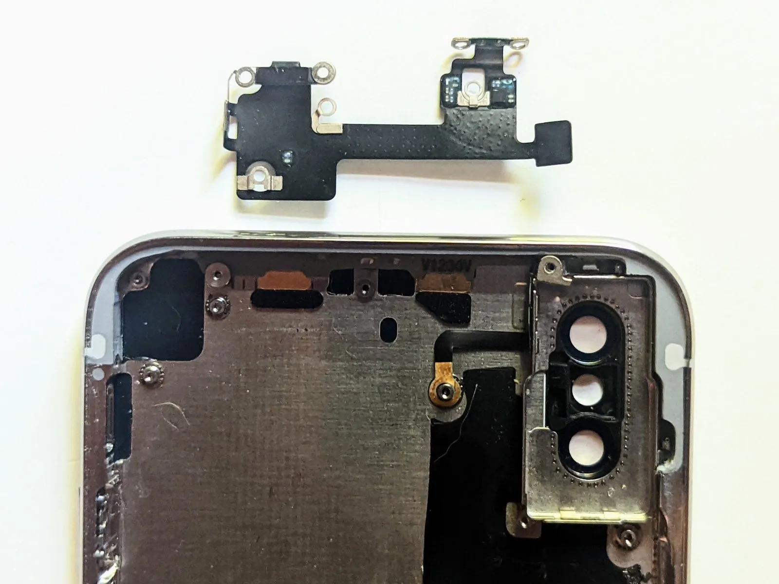
Carefully detach the front-facing camera module.
Step 55 | Logic Board
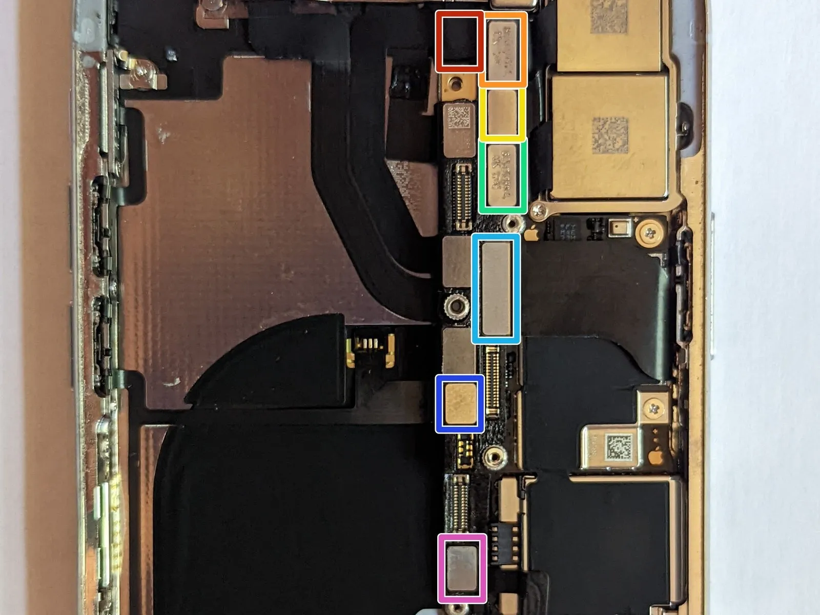
- Carefully detach the connectors from these cables:
Please provide the original text you want me to rewrite. I need the sentence or instruction to be able to fulfill your request.The device incorporates a WiFi antenna.Ensure proper alignment and secure fastening of the component.
Please provide the original text you want me to rewrite. I need the sentence or instruction to be able to fulfill your request.Employ the designated wide-angle lens.Ensure the electrical connector is properly seated and secured.
Please provide the original text you want me to rewrite. I need the sentence or instruction to work with.Locate the power button, flash, and microphone.Secure the electrical coupling.
Please provide the original text you want me to rewrite. I need the sentence or instruction to work with.Employ the zoom lens designed for capturing distant subjects.Ensure the component is properly connected.
Please provide the original text you want me to rewrite. I need the sentence or instruction to be able to fulfill your request.Secure the flexible connector.Ensure the electrical connector is properly seated and secured.
Please provide the original text you want me to rewrite. I am ready when you are.Activate the power button or utilize the wireless charging capability.Ensure the electrical connector is properly engaged.
Please provide the original text you want me to rewrite. I need the sentence or instruction to be able to fulfill your request.The device responsible for wireless communication is the cellular antenna.Ensure the electrical connector is properly seated.
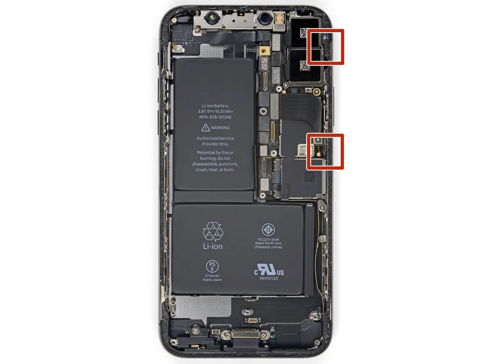
Step 56 | WiFi Antenna Connector

Carefully detach theConnect the WiFi antenna, ensuring it is securely fastened to the designated connector and aligned per the manufacturer's specifications, using a torque of 8 in-lbs with a 5mm wrench, and observing the ESD warning to prevent damage.Attach the cable to the connector.
Step 57 | Wide-Angle Camera Connector

Step 58 | Power Button / Flash / Microphone Connector

Step 59 | Telephoto Camera Connector
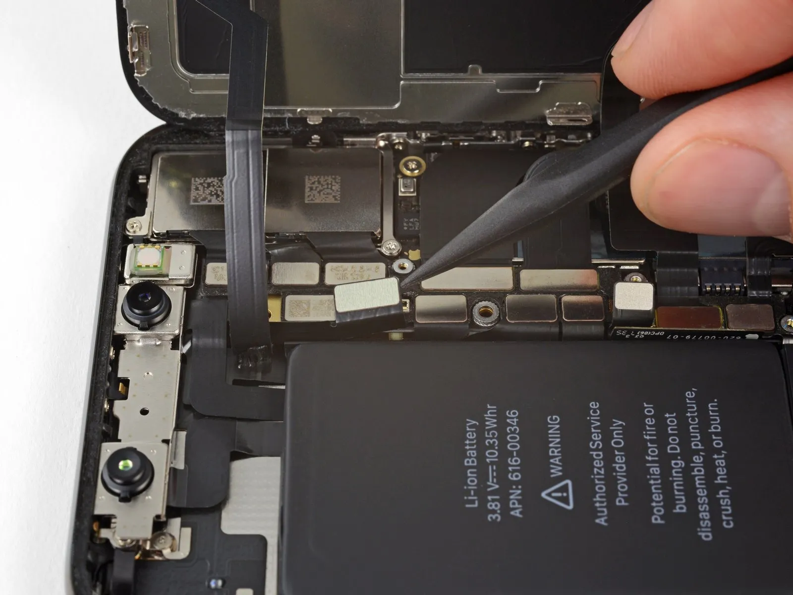
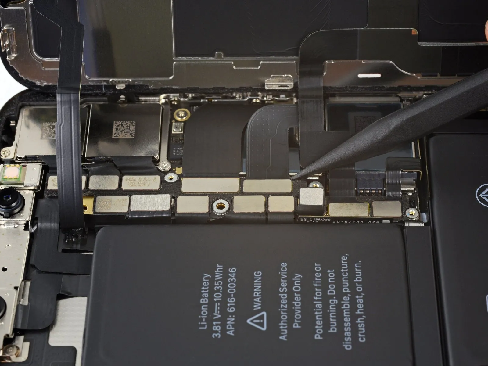
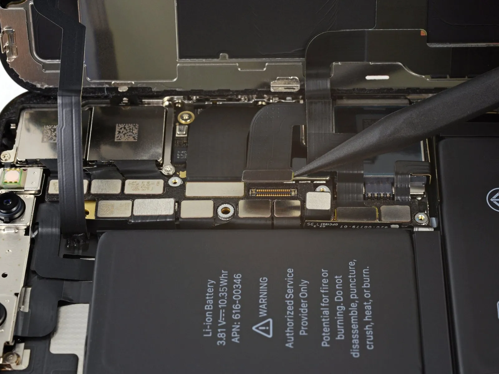
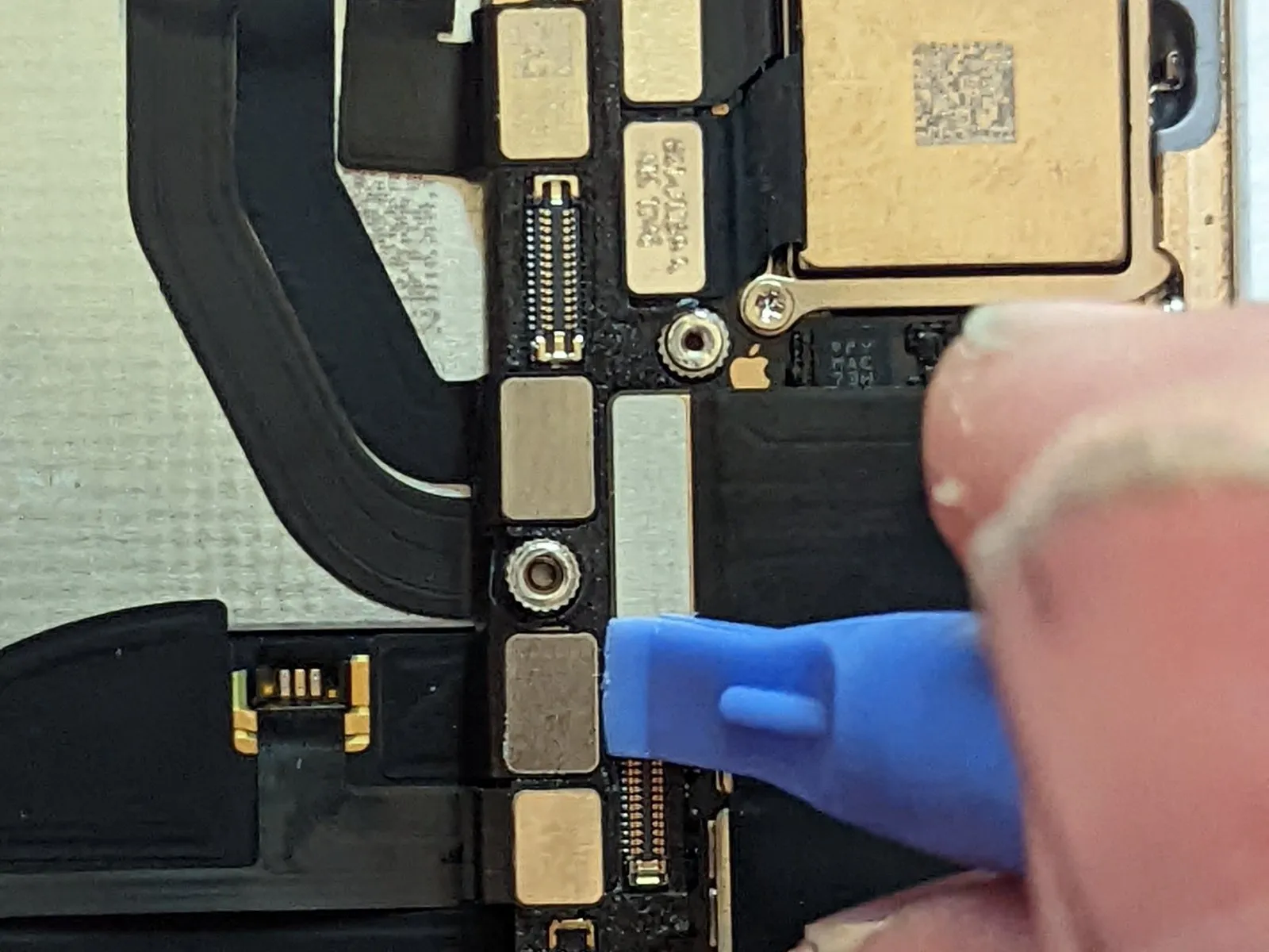
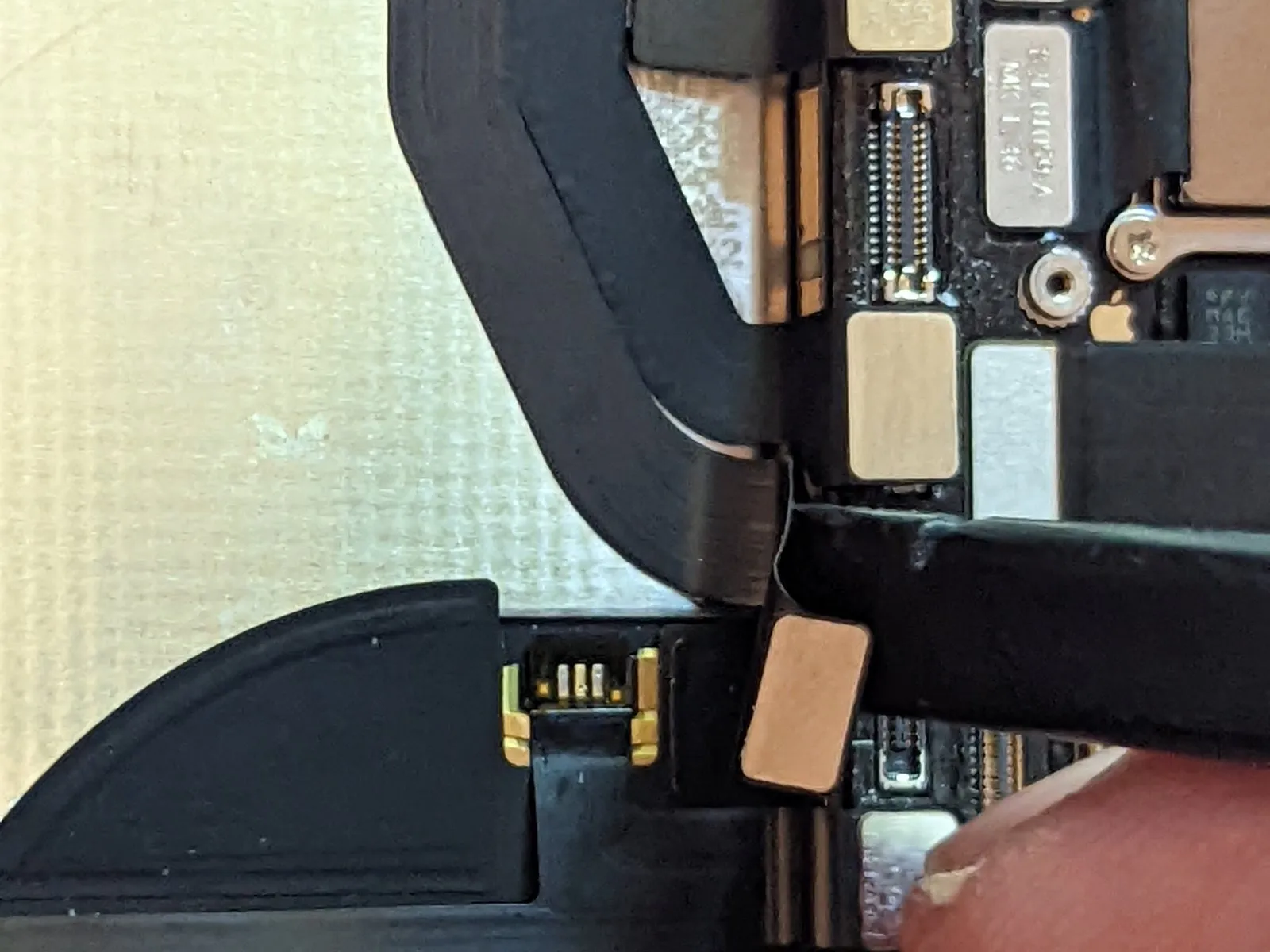
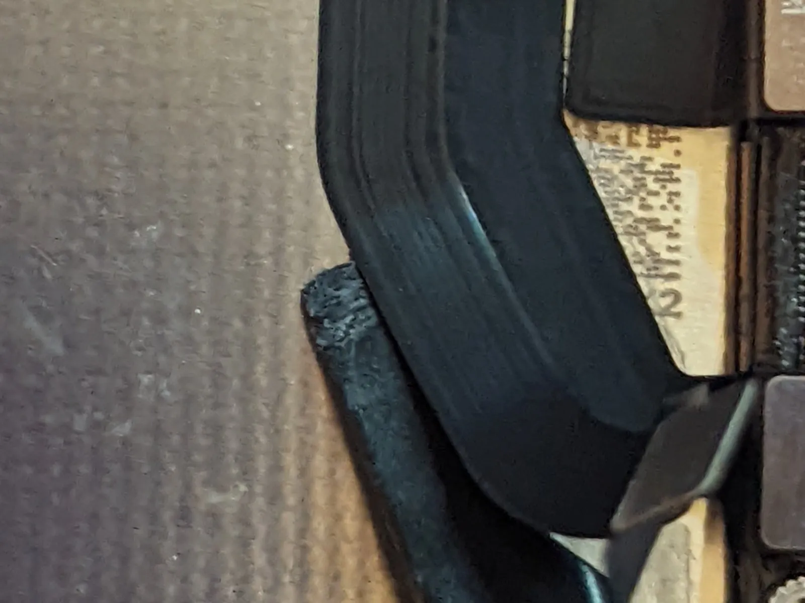
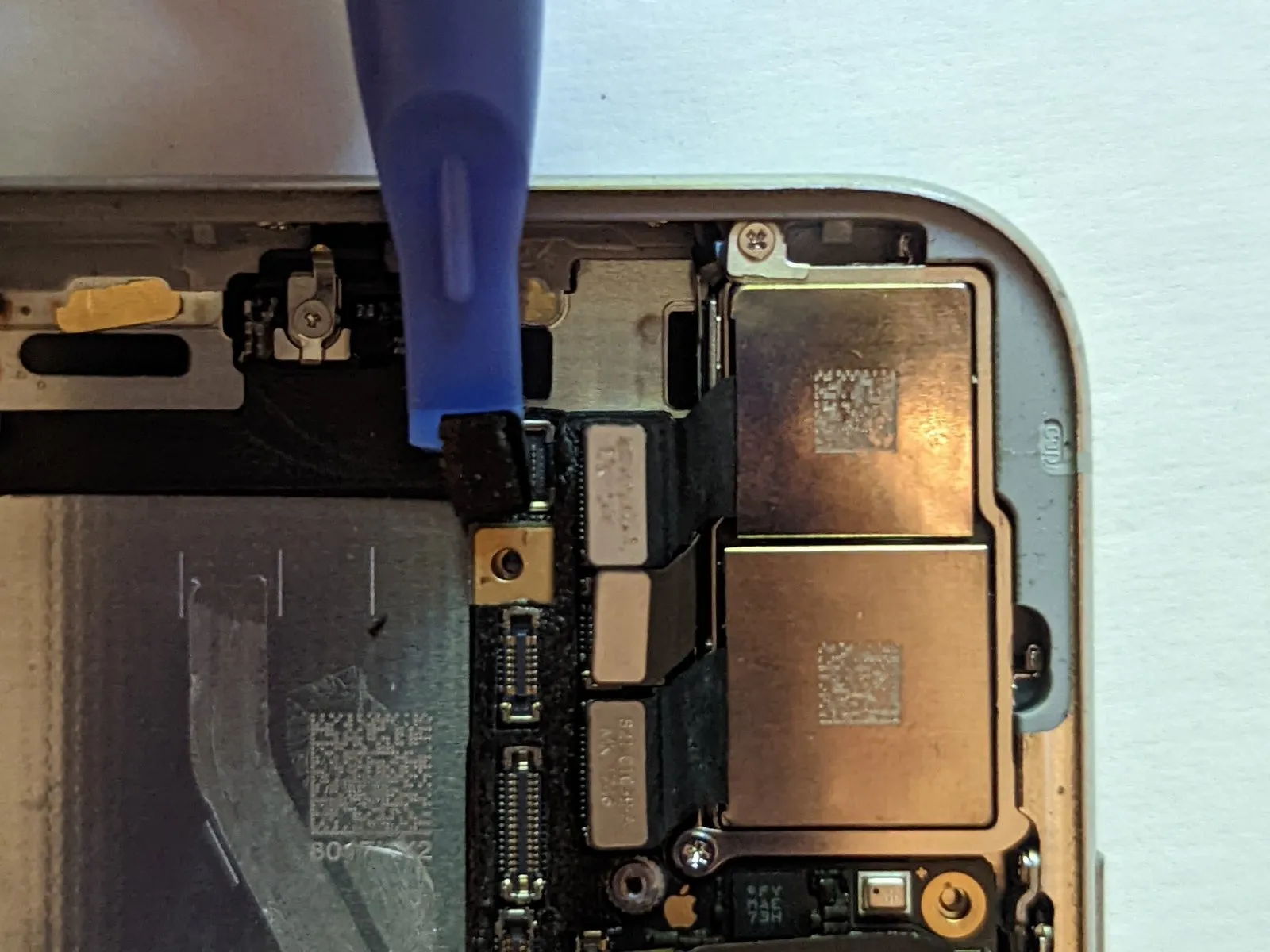
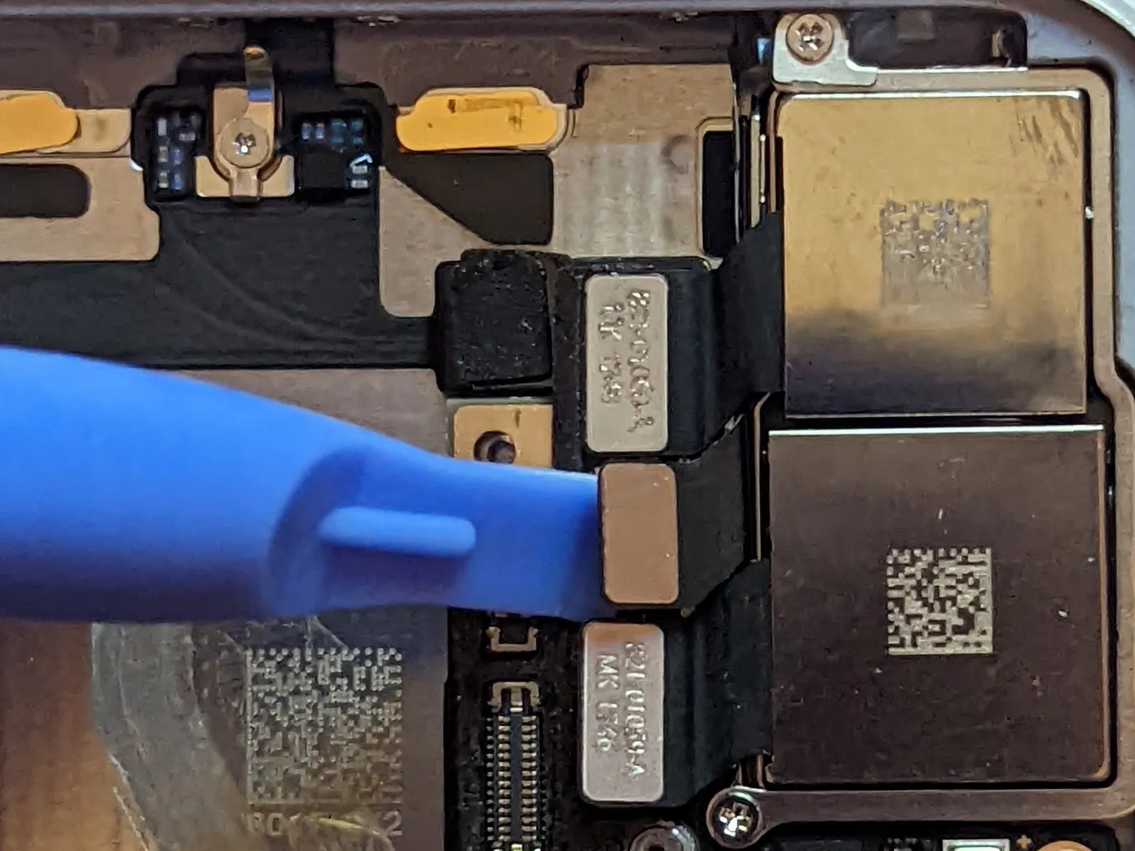
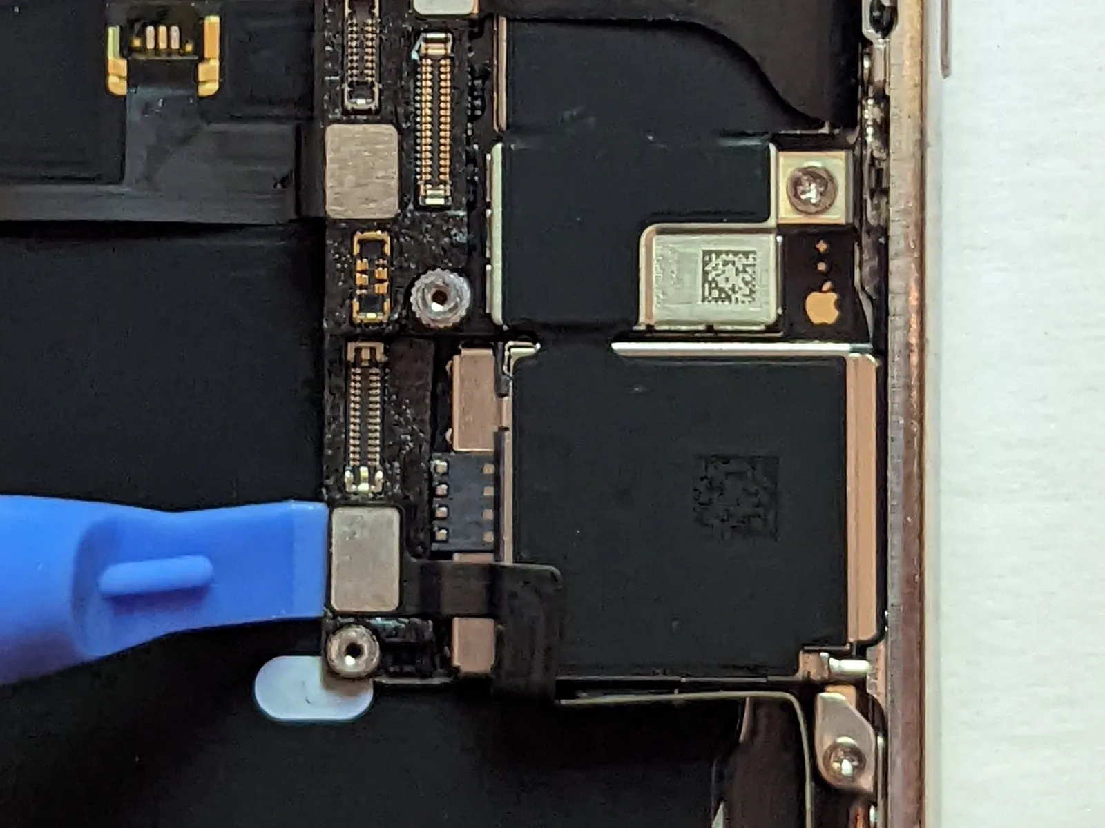
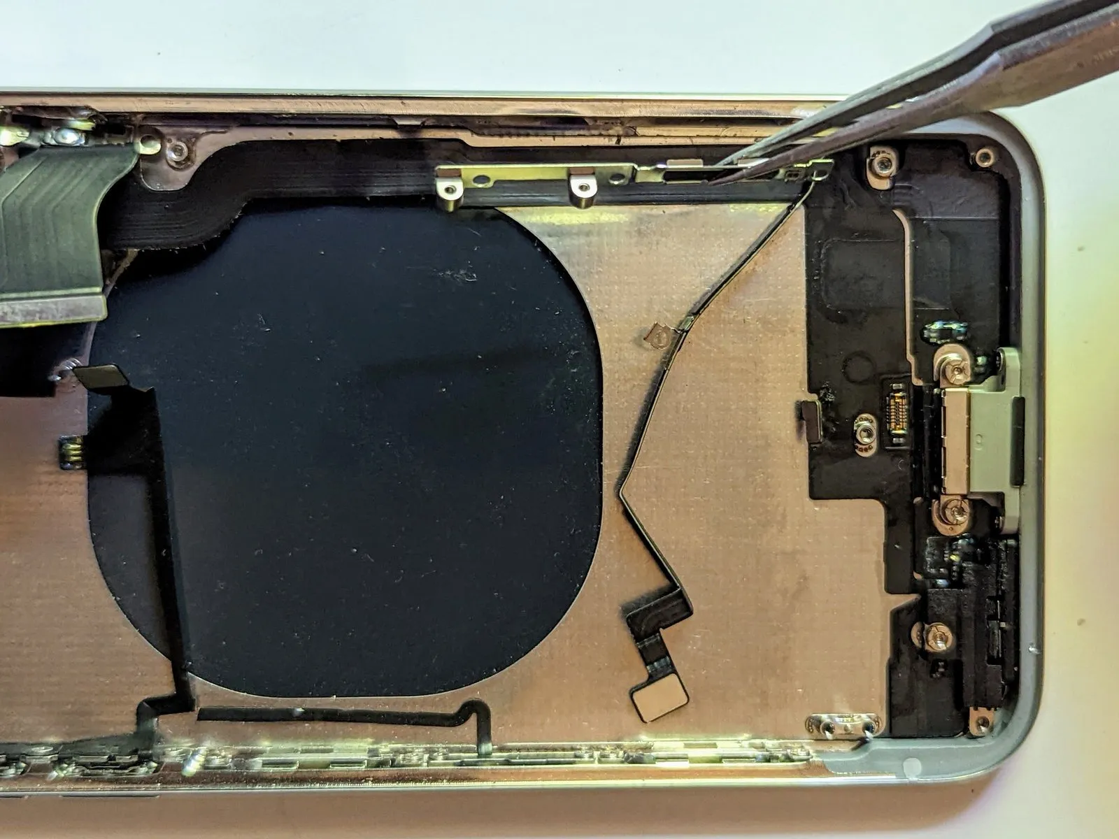
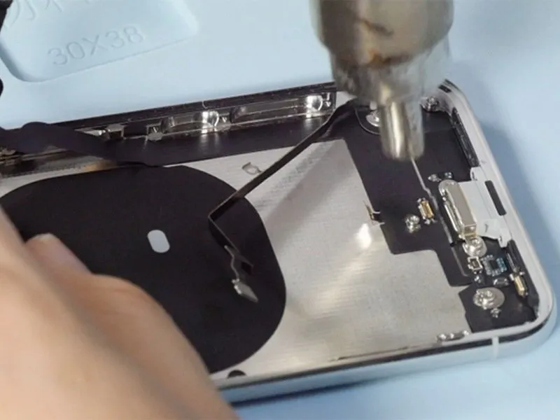
Step 60 | Dock Flex Connector
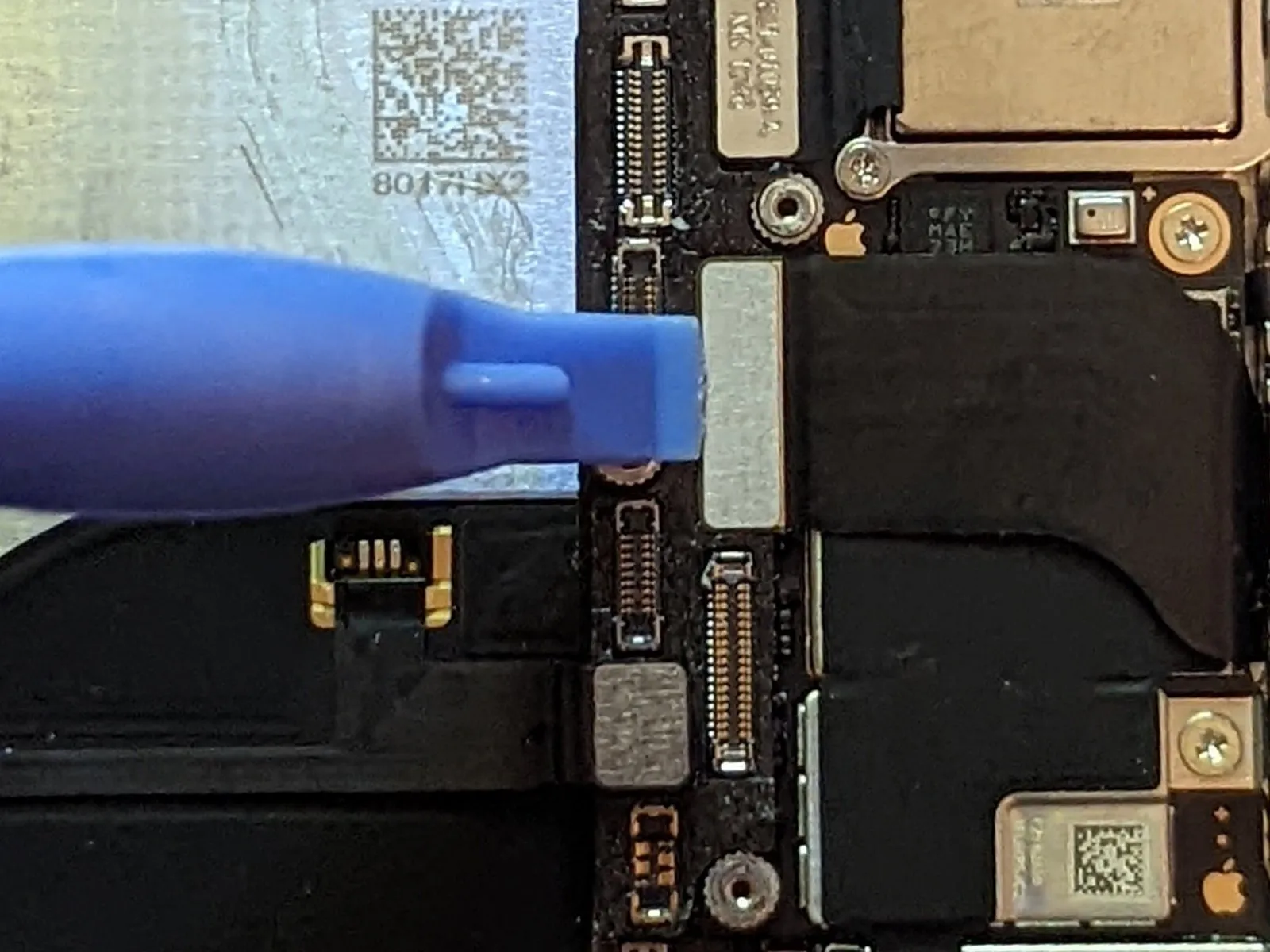
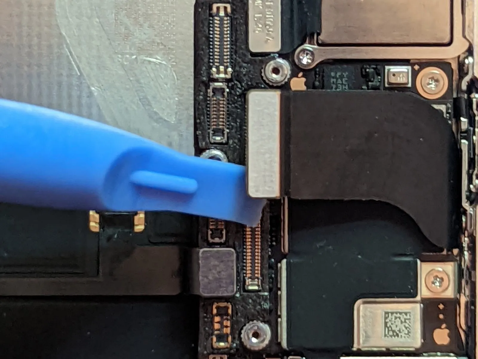
- Carefully detach the Dock Flex cable connector.
- Carefully flex the cable.Ensure the angle is precisely 90 degrees.Raise the component vertically to provide sufficient space for logic board removal.
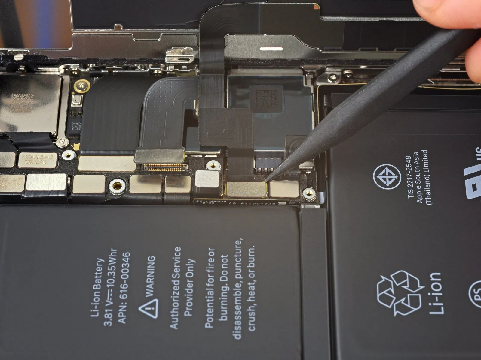
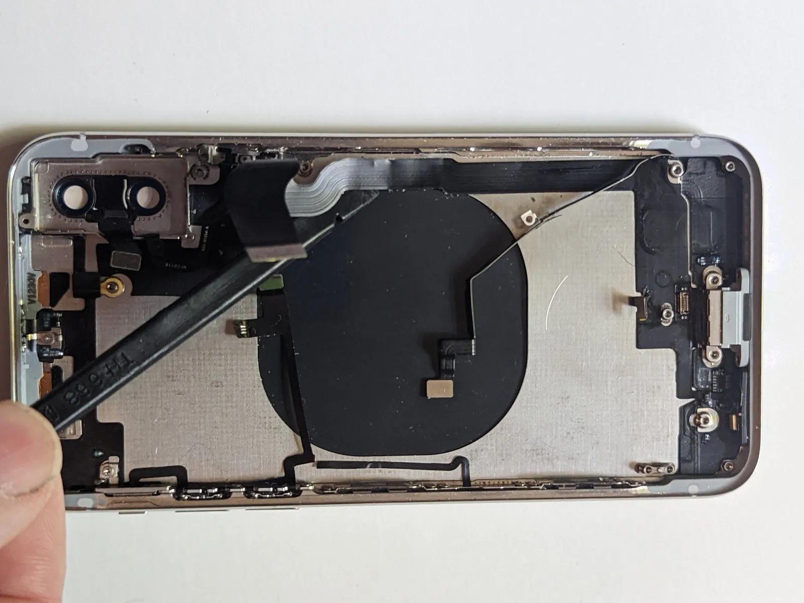
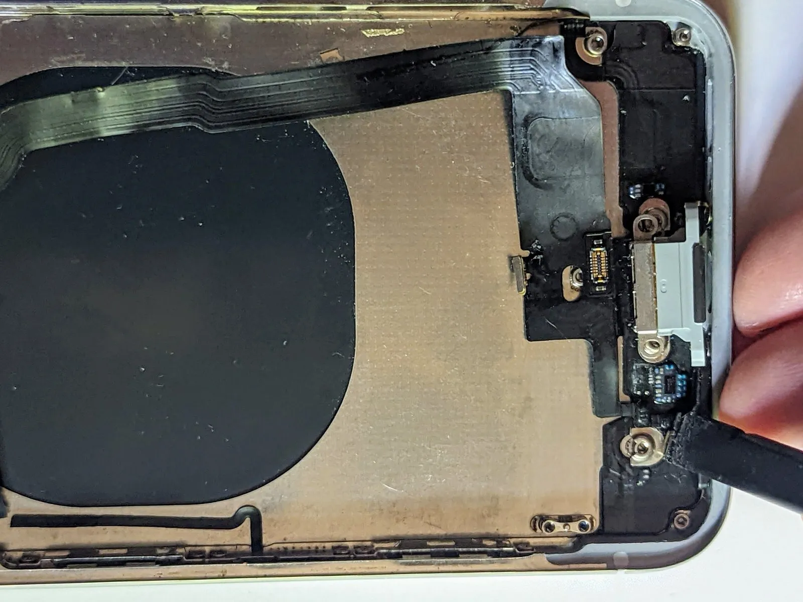
Step 61 | Button / Wireless Charging Connector
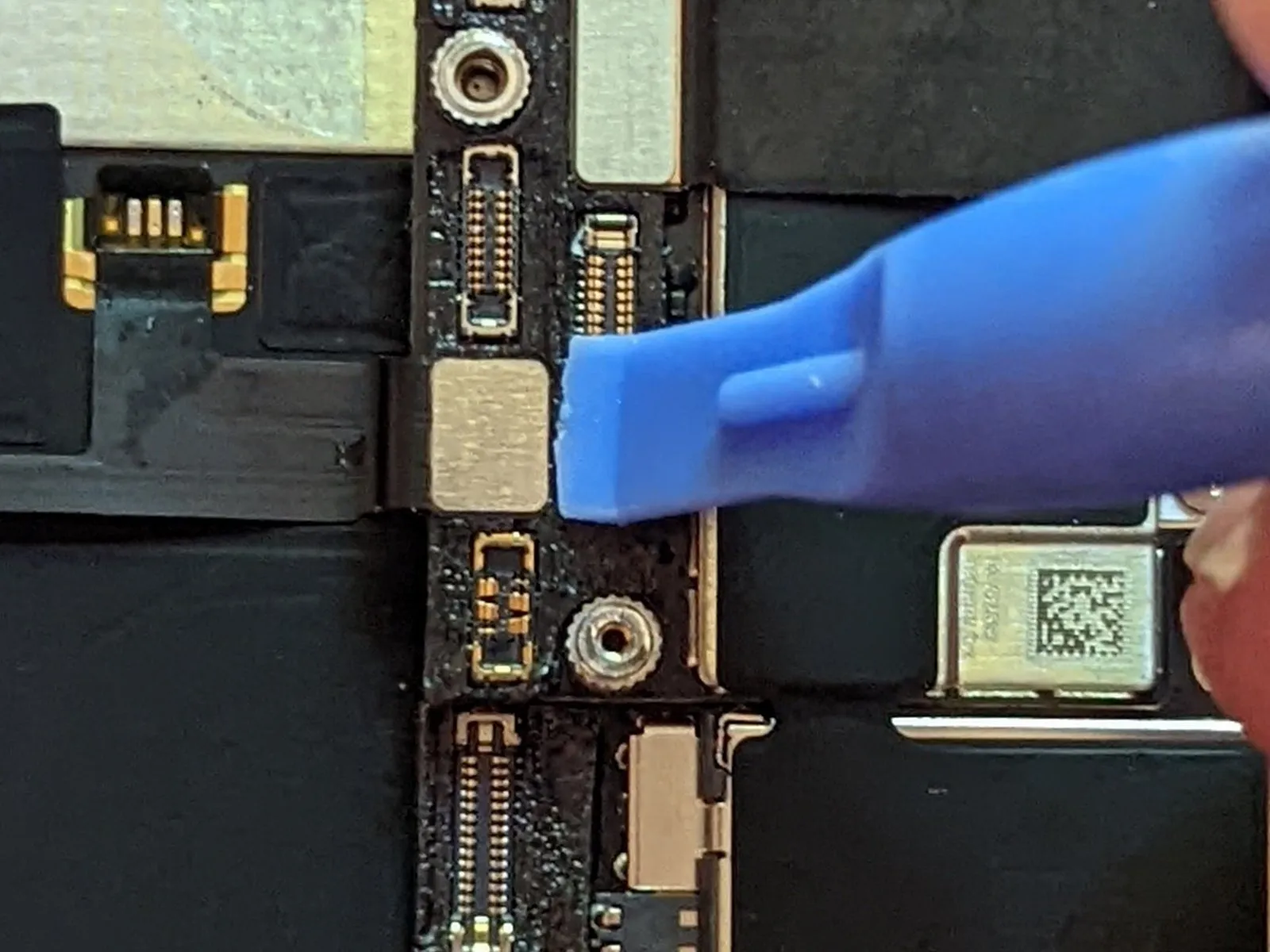
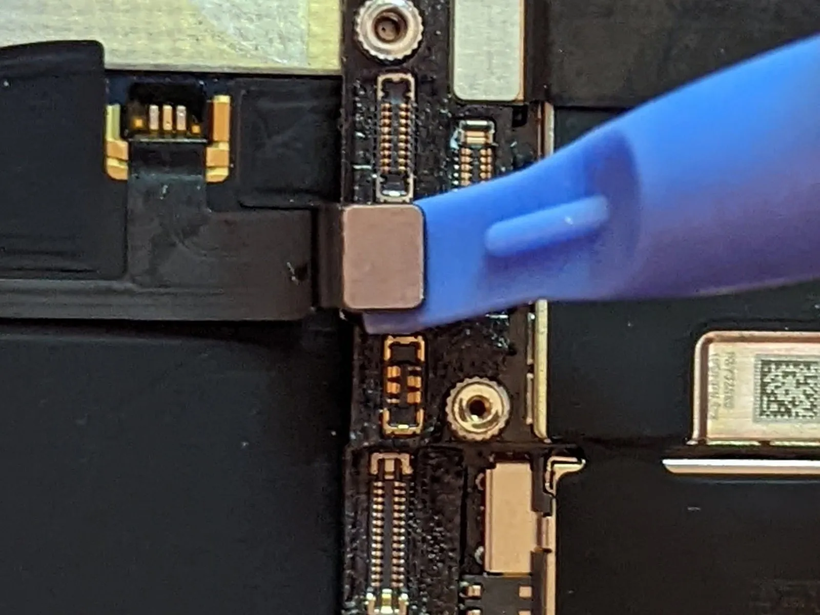
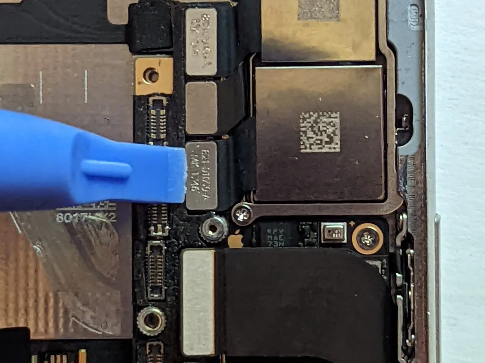
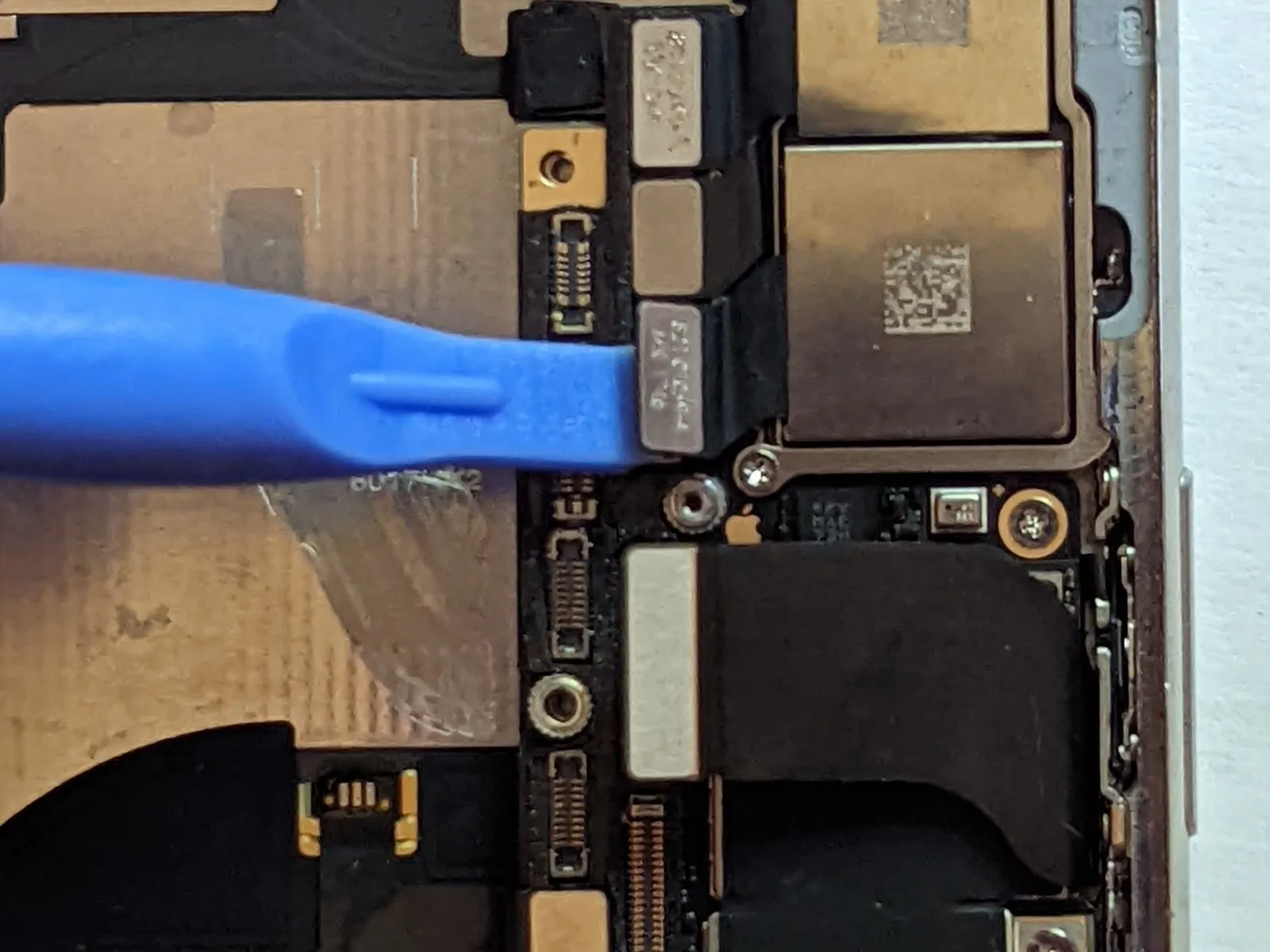
Step 62 | Cellular Antenna Connector

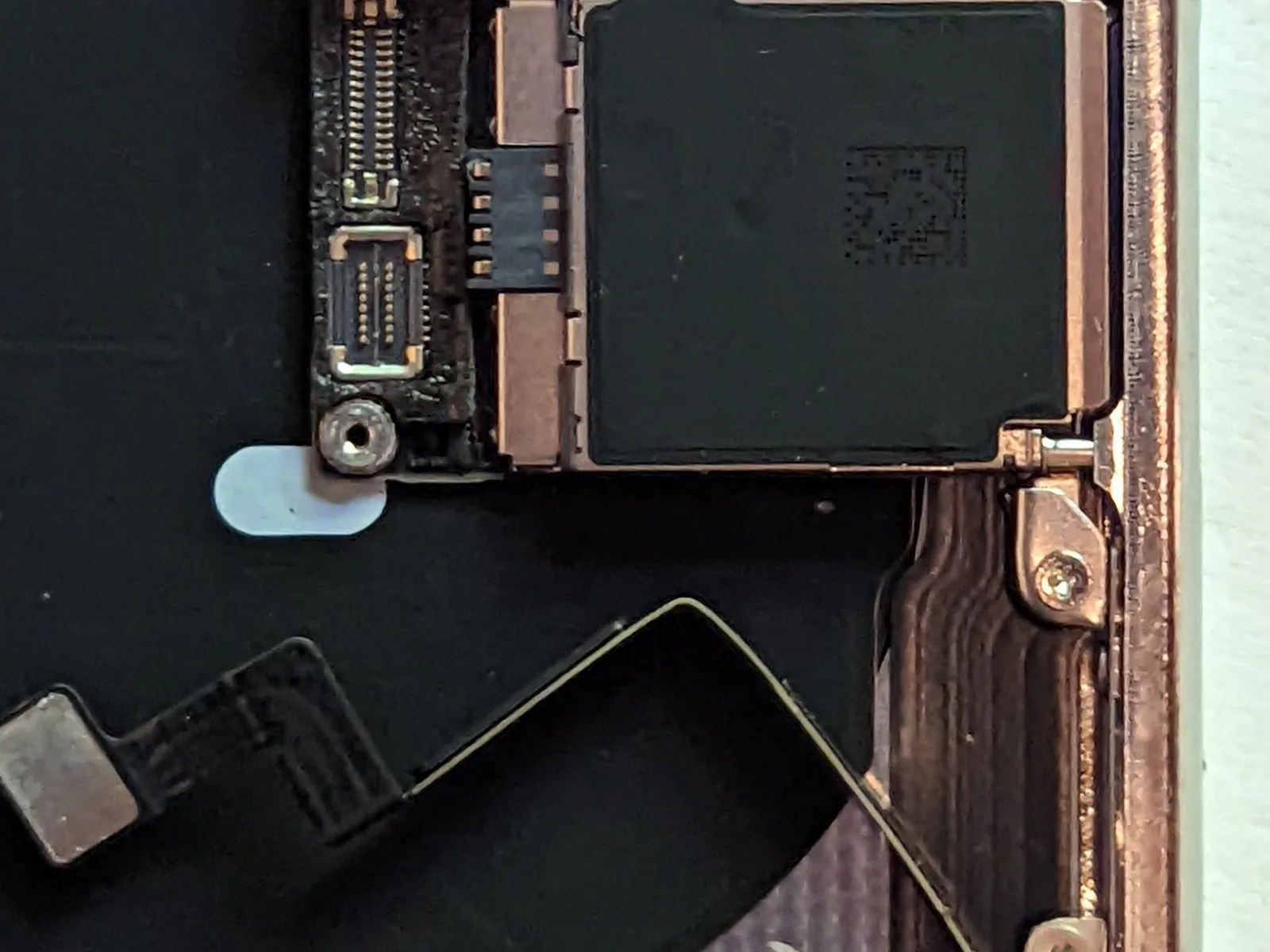
- Carefully detach the Cellular Antenna cable connector.
- Carefully reposition the cable to prevent interference with subsequent steps.
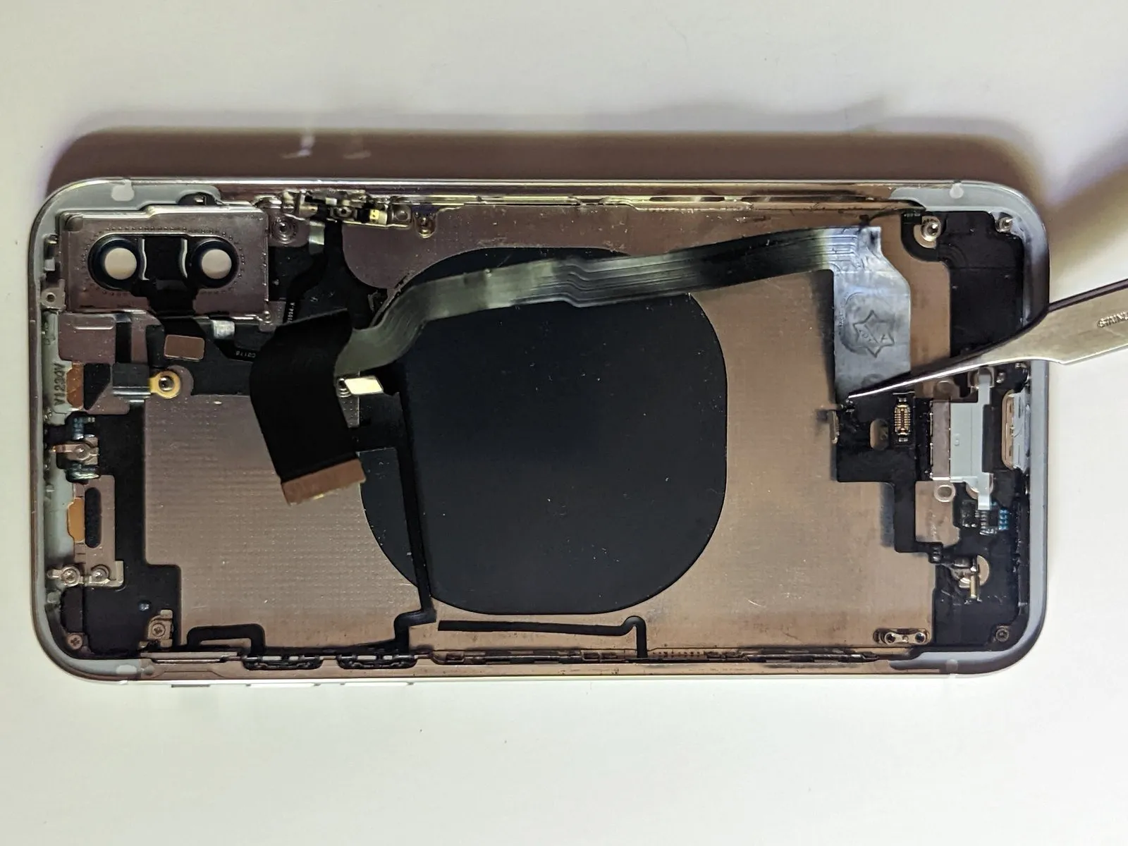
Step 63
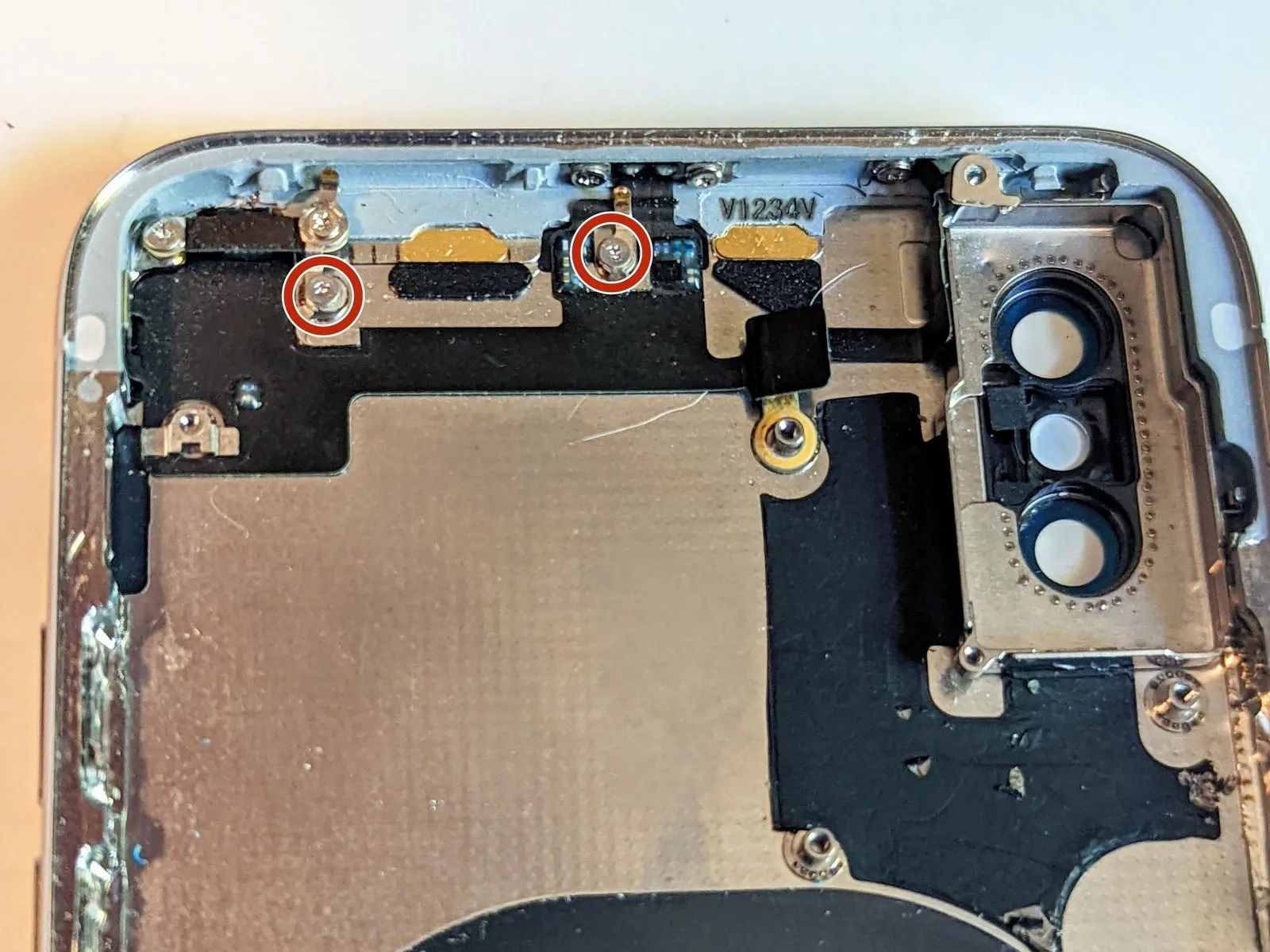
Before proceeding, ensure the SIM card tray is extracted, as its presence will prevent logic board removal. If this step was not completed previously, perform it now.
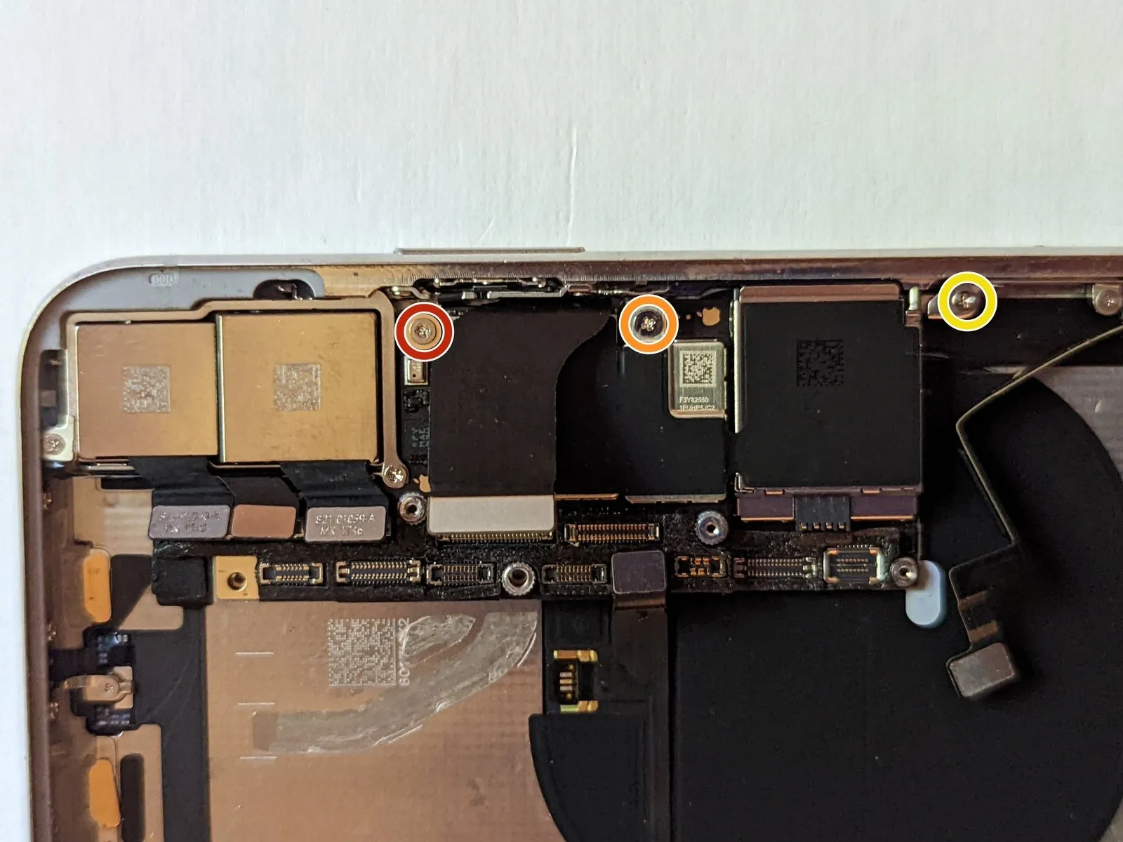
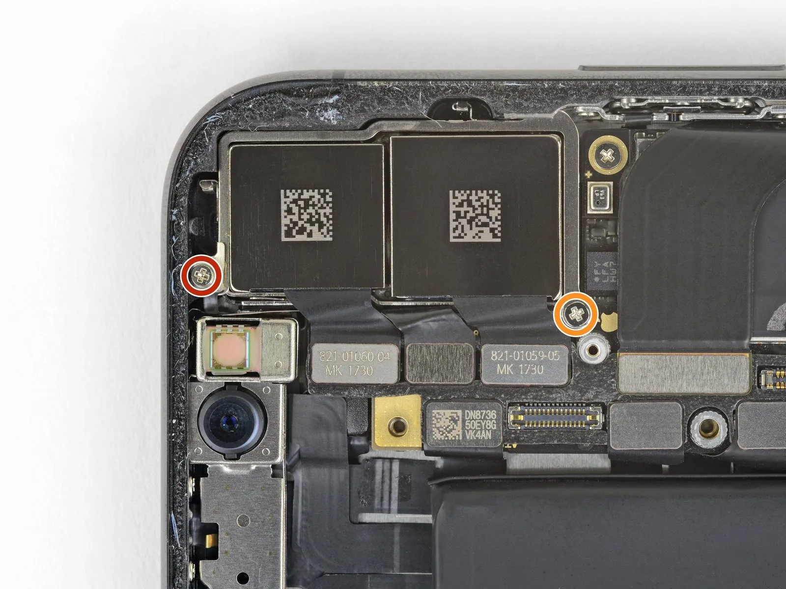
Using a Phillips screwdriver, detach the two screws that secure the component in place.
Use a Phillips screwdriver to tighten a screw with a 2.7 mm head.
Secure the component with a Phillips screwdriver, using a 2.1 mm head.
Carefully detach the component, ensuring all associated fasteners are released and no damage occurs during the process.Use a Phillips screwdriver to tighten the screw, which has a 2.0 mm head..
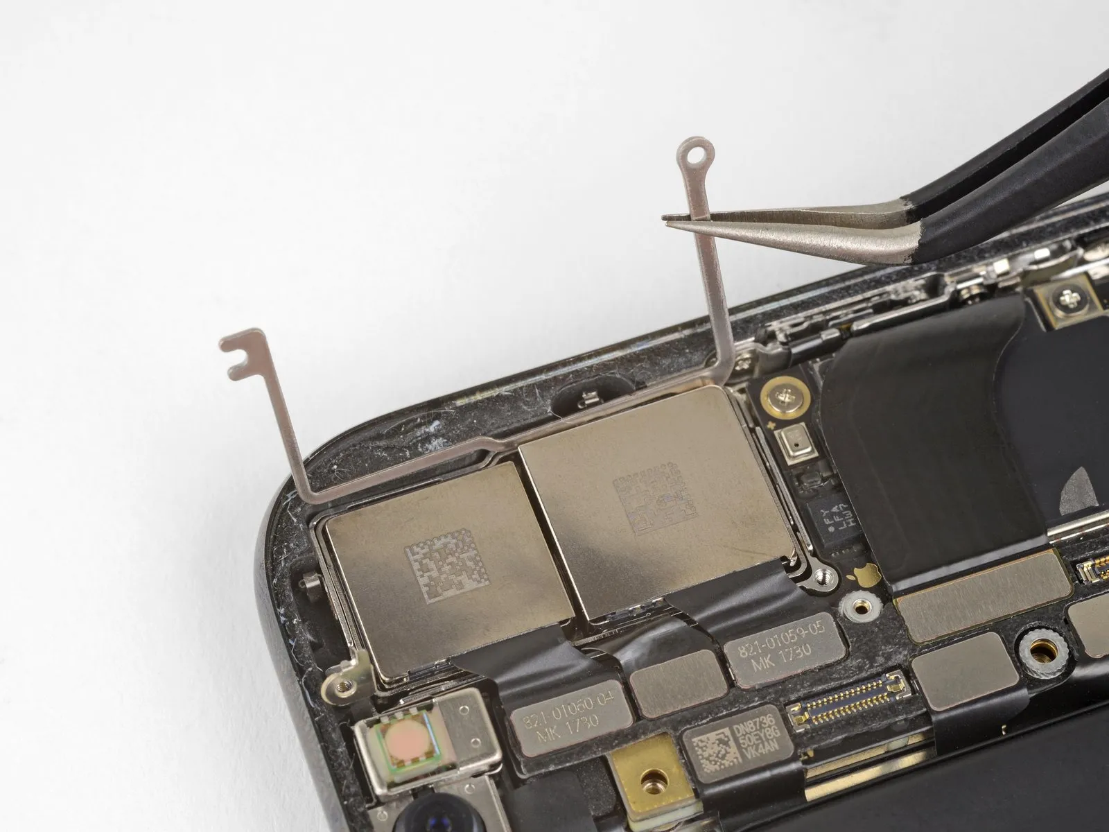
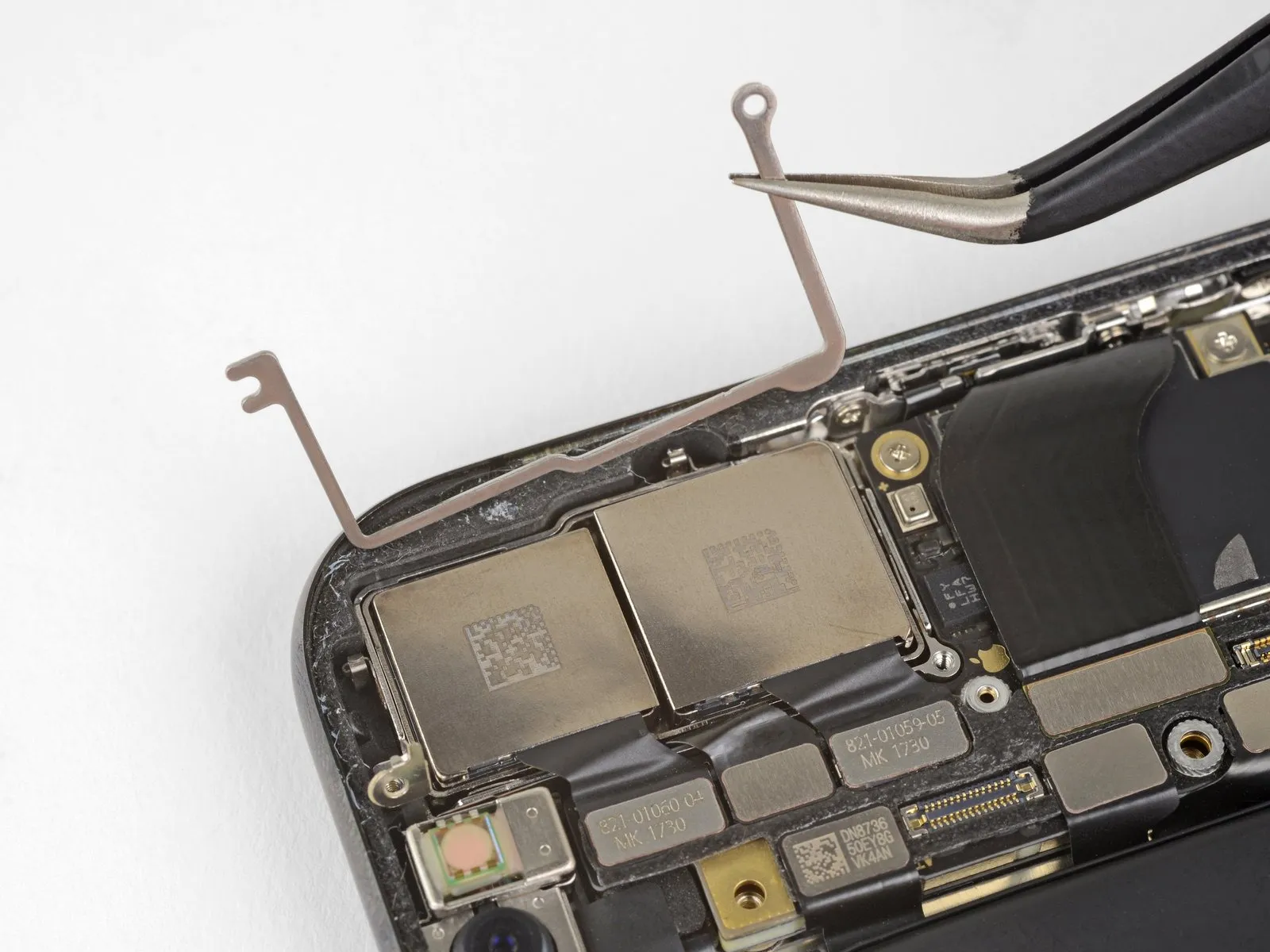
Carefully detach the grounding tab.
Ensure the metal grounding tab is reinstalled with the identical positioning it held previously.
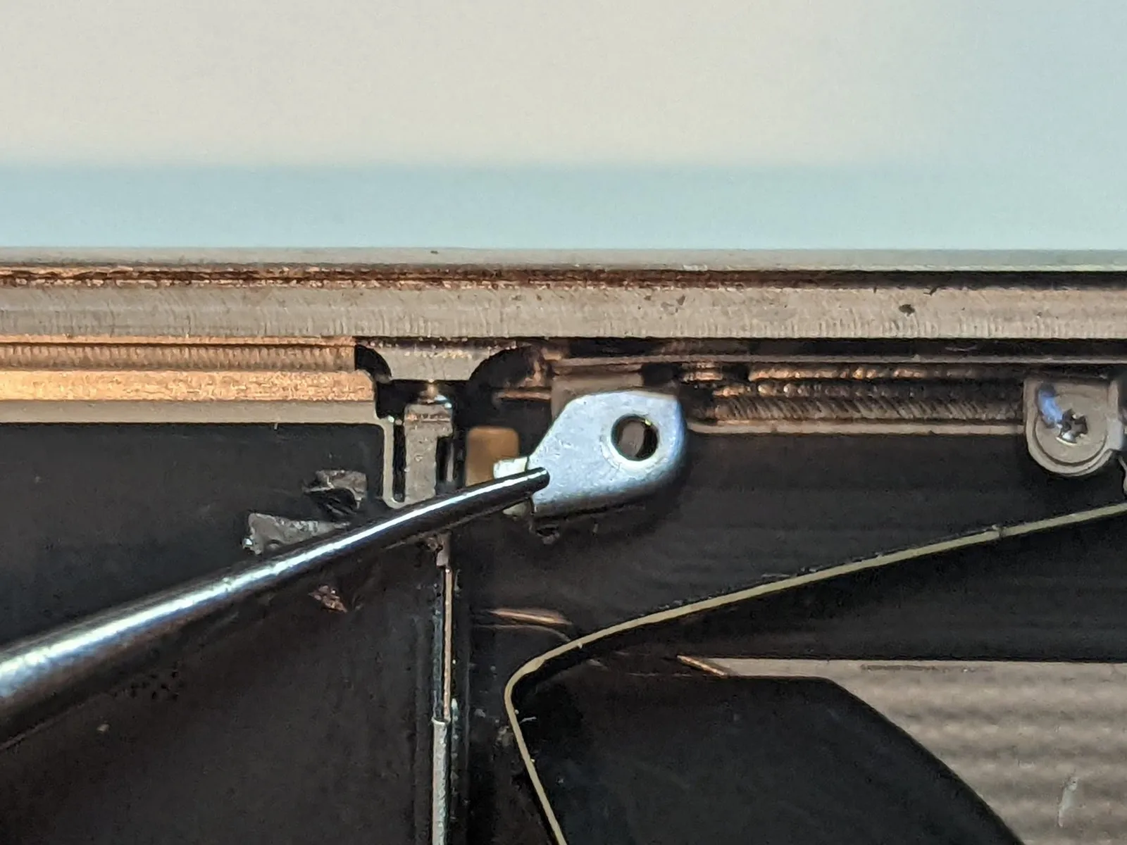
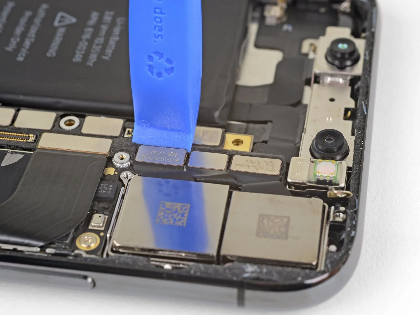
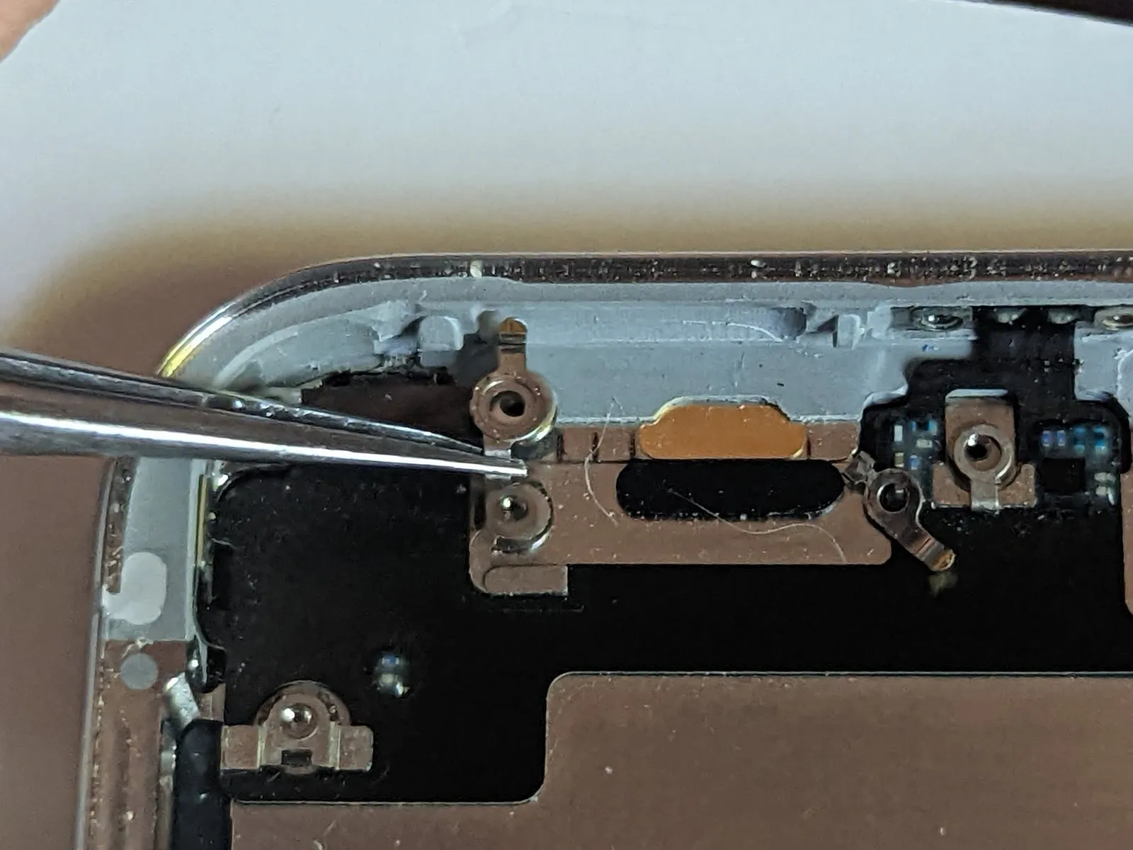
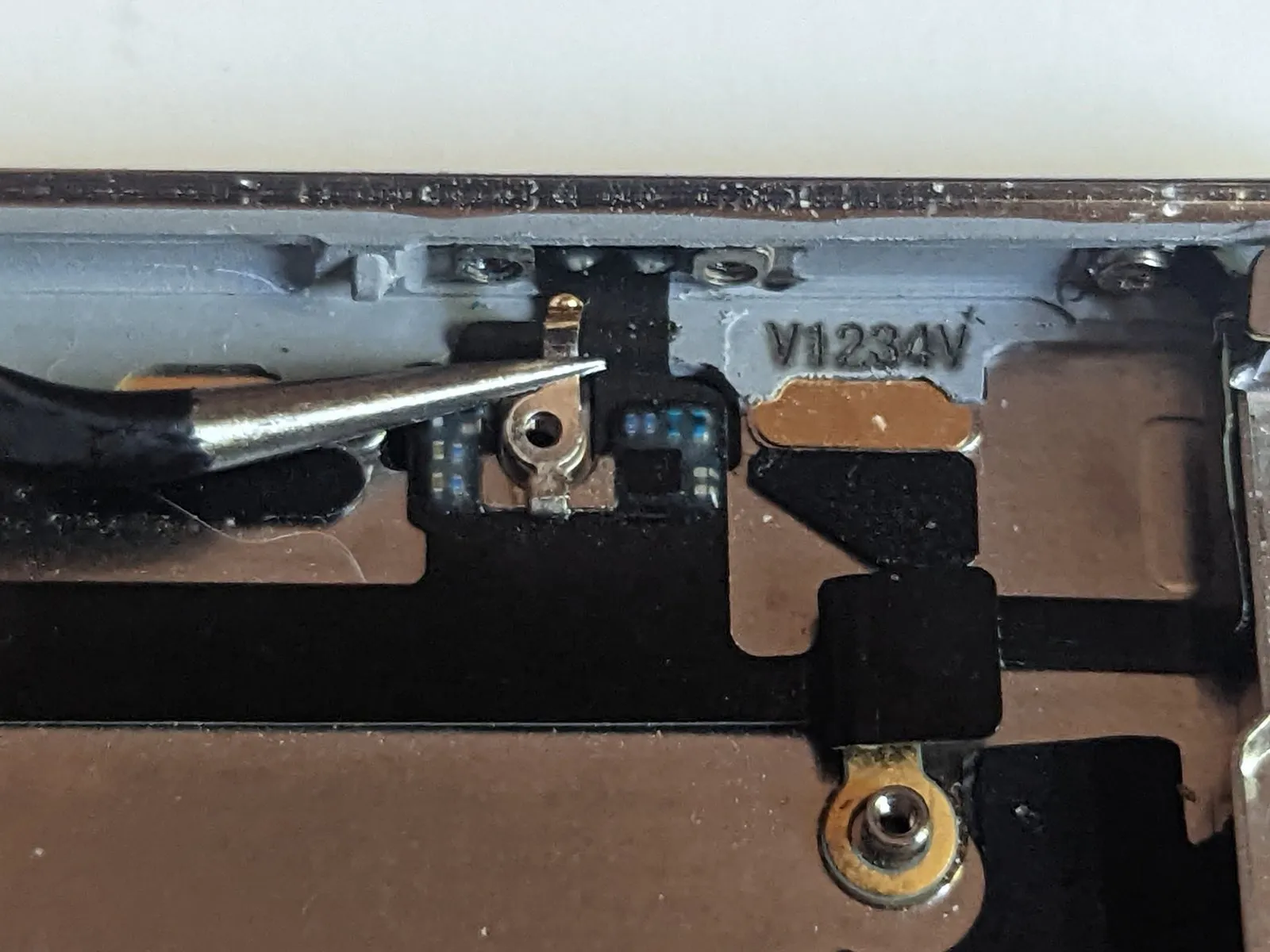
Step 64 | Retract the SIM Eject Pin
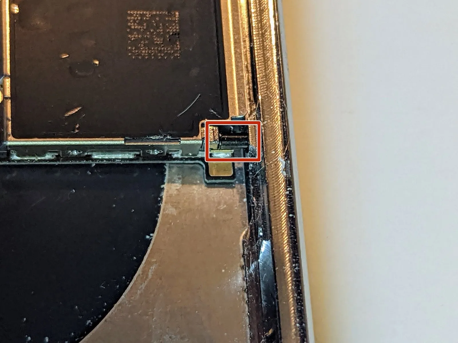
To allow logic board removal, ensure the ejection pin, which extends from the frame when the SIM card is removed and engages the SIM card carrier's lever, is manually retracted and fully seated within the frame.
Step 65
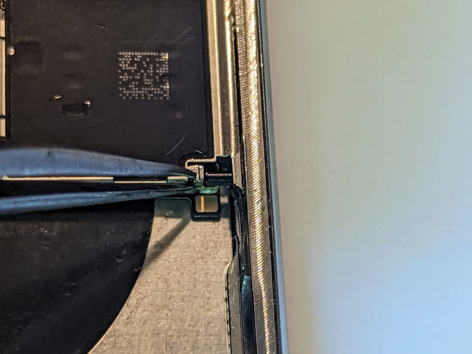


- Employ the specified tool to perform the action.Utilize two tweezers with a precision tip.Push the SIM card eject lever in the direction of the device's side.
- Following completion, the eject lever's position will confirm proper adjustment, allowing the logic board to be detached as the pin is no longer an obstruction.
Step 66

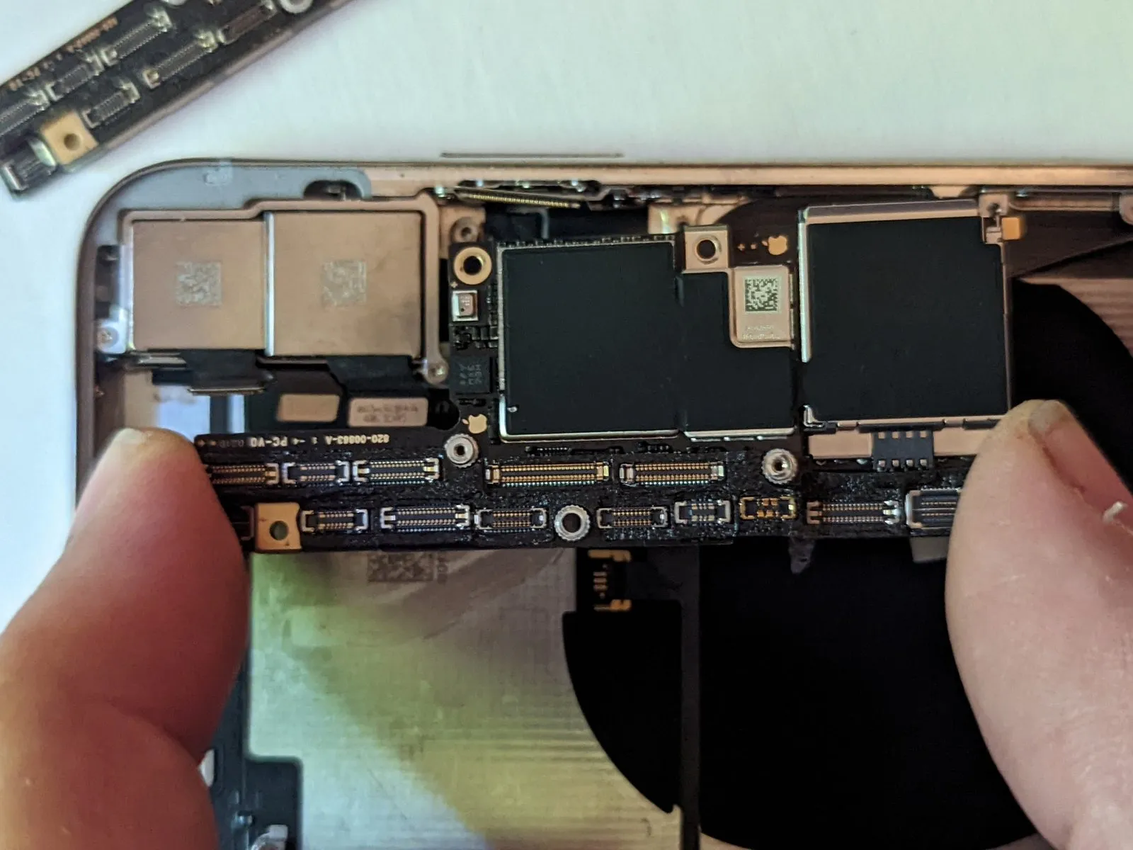
To detach the logic board assembly, raise it vertically, ensuring evenness, as it's affixed to the upper board via two stand-offs that pass through the lower board.
Step 67 | Rear-Facing Cameras
- Detach two.Use a Phillips head screwdriver.Using a 5mm Allen wrench, tighten the four M4x10 screws to 4.5 Nm, ensuring the camera bracket is firmly affixed.
- Begin the process by executing the action designated as "One."Use a screw with a diameter of 2.3 millimeters.
- Begin the process with the number one.Use a screw with a diameter of 2.0 millimeters.
Step 68


Carefully maneuver the small metal grounding bracket aside using tweezers, avoiding upward force because it's affixed to a delicate flex cable.
Step 69

- Detach the camera bracket by raising it upwards from the side nearest the battery.
- Begin reassembly by positioning the bracket’s outer edge so the right-side tab aligns with the space separating the phone’s case and the camera module, then rotate the bracket downwards to secure it over the camera module.
Step 70
- Employ a 3/8-inch socket wrench to loosen the retaining bolt, ensuring you maintain a firm grip and avoid excessive force to prevent damage to the threaded section.Use a specialized prying tool.Use a fingernail or similar tool to carefully separate the two camera connectors by applying upward pressure directly on each connector to release them from their respective sockets.
Step 71
- Using a pointed tool, apply pressure to the designated location.Use a plastic pry tool to gently separate.Align the camera module's lower-right edge with a tiny indentation located there.
Using a prying tool, carefully apply leverage to disengage the camera assembly from the iPhone.
Step 72
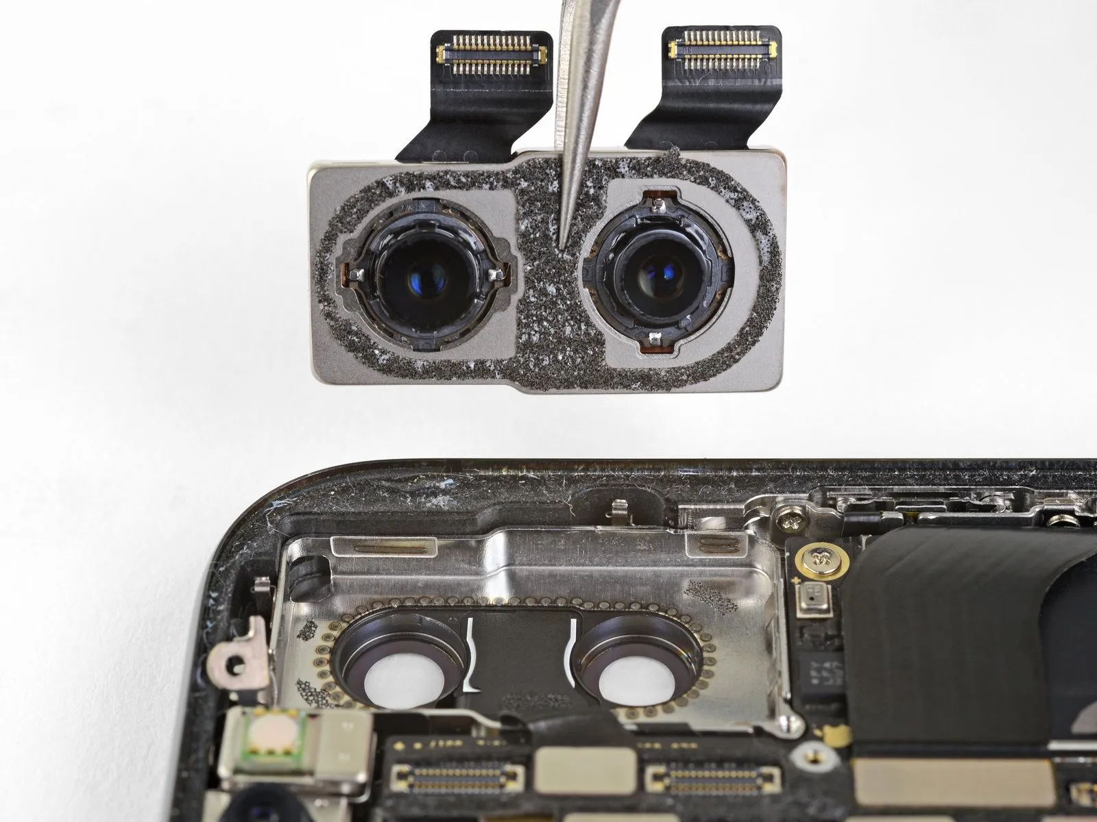
- Carefully detach the rear camera assembly.
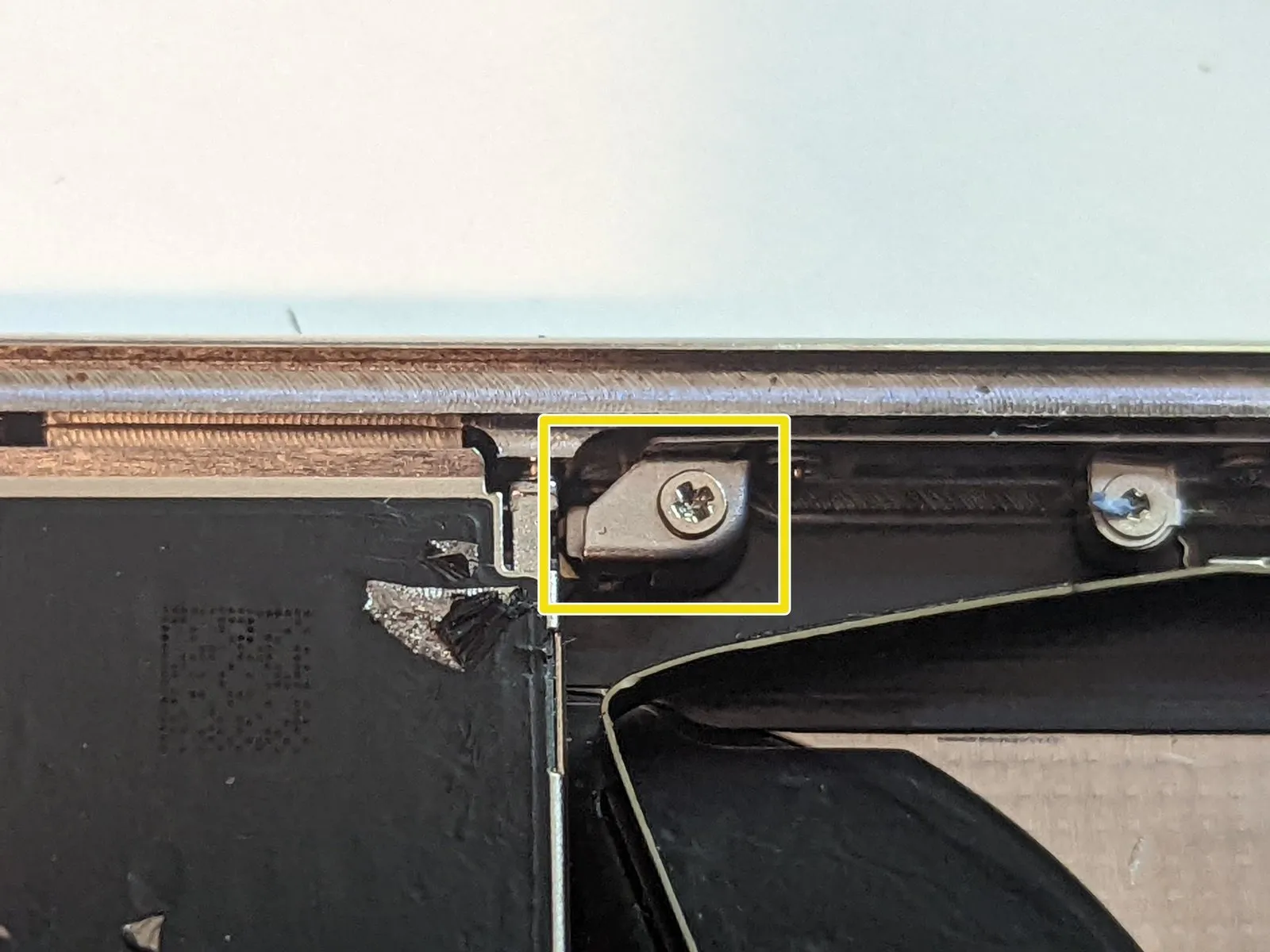
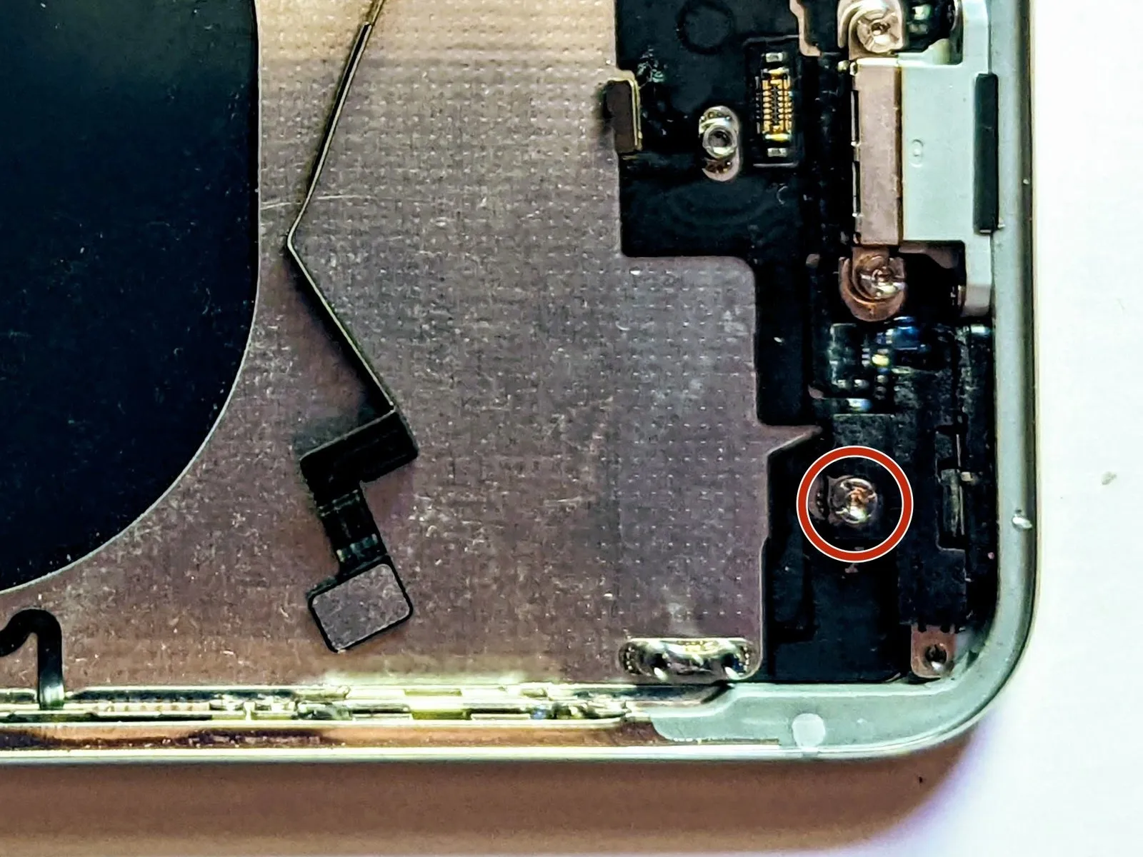
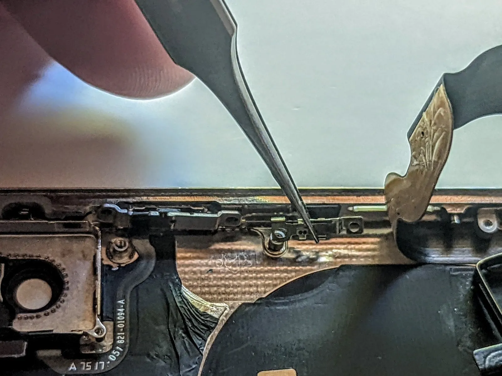
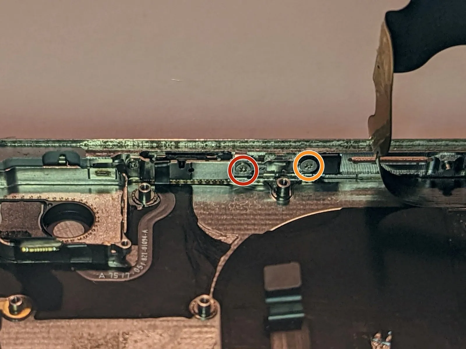
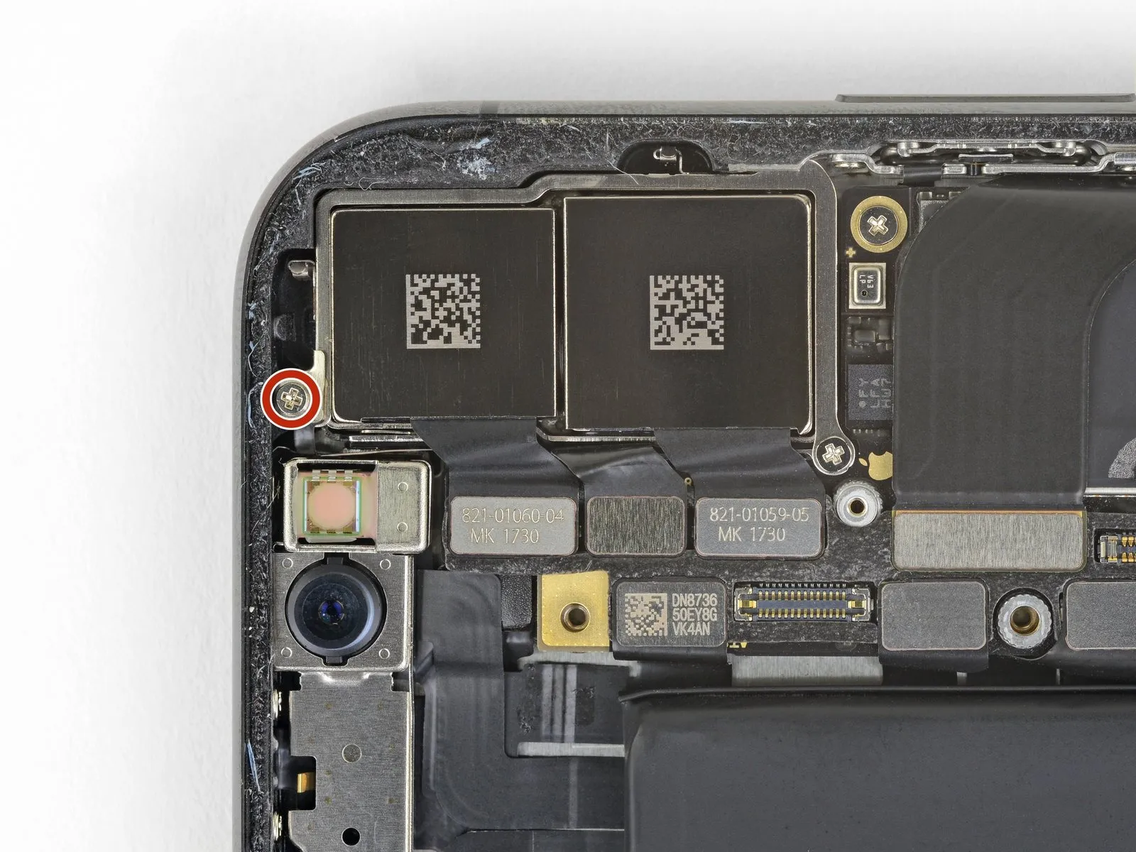
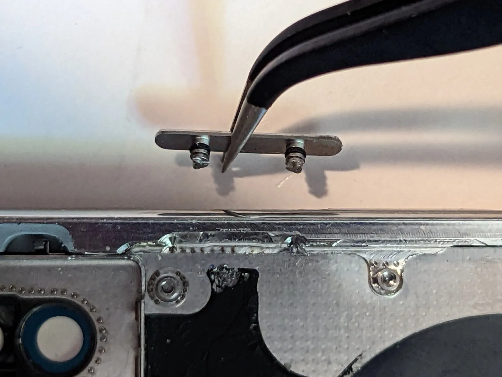
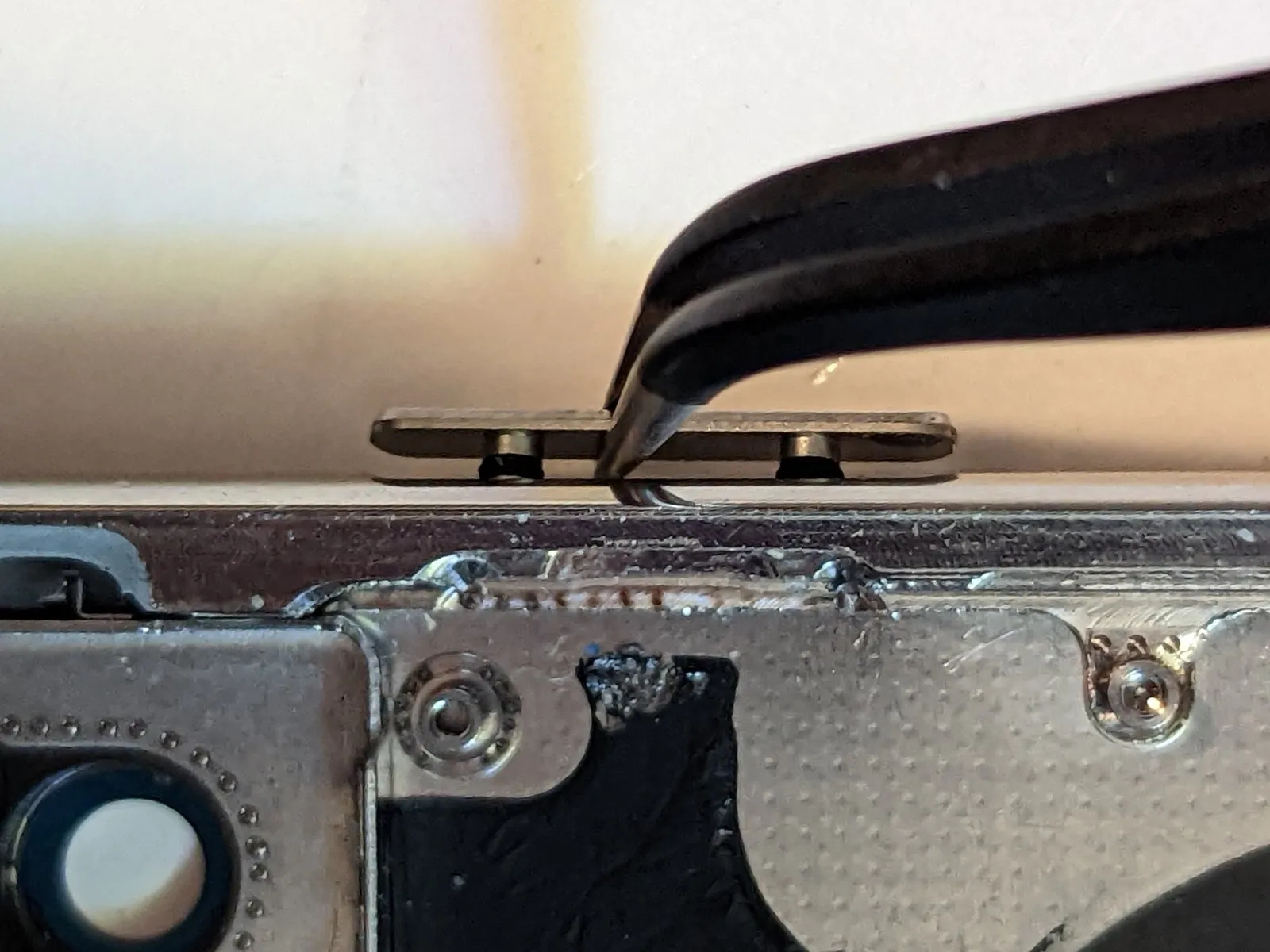
Step 73 | Bottom Right Screen Retainer
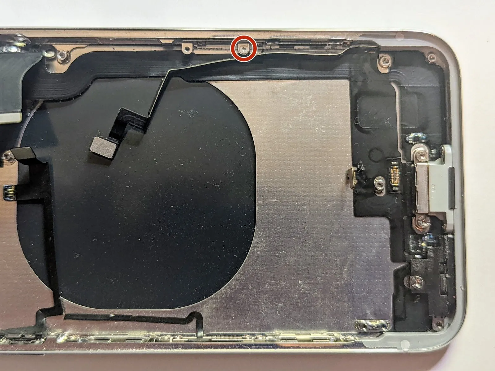
- Carefully detach the component, ensuring no damage occurs.Use a Y000 screwdriver to loosen the 1.2-millimeter screw.Attach the cellular antenna cable firmly to the screen retainer.
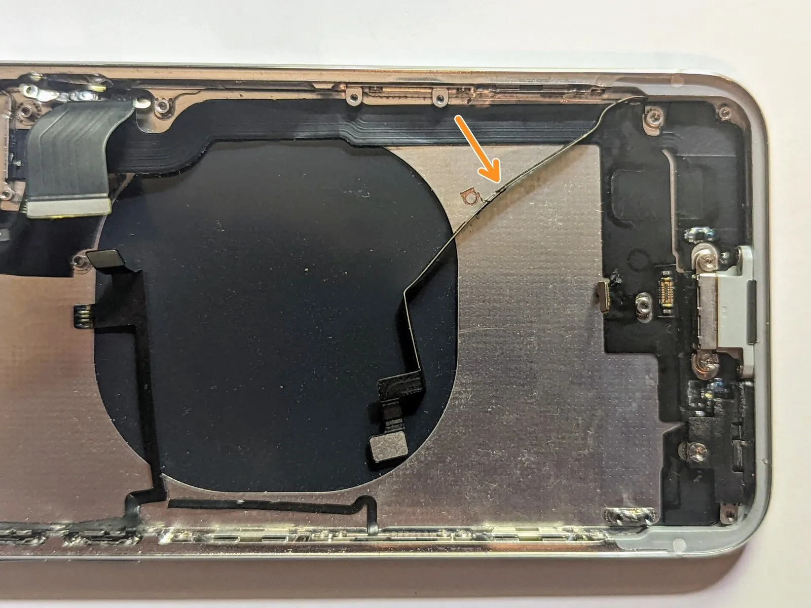
- To reach the screws that hold the retainer in place on the case's side, maneuver the antenna cable so it's not obstructing access.
Step 74
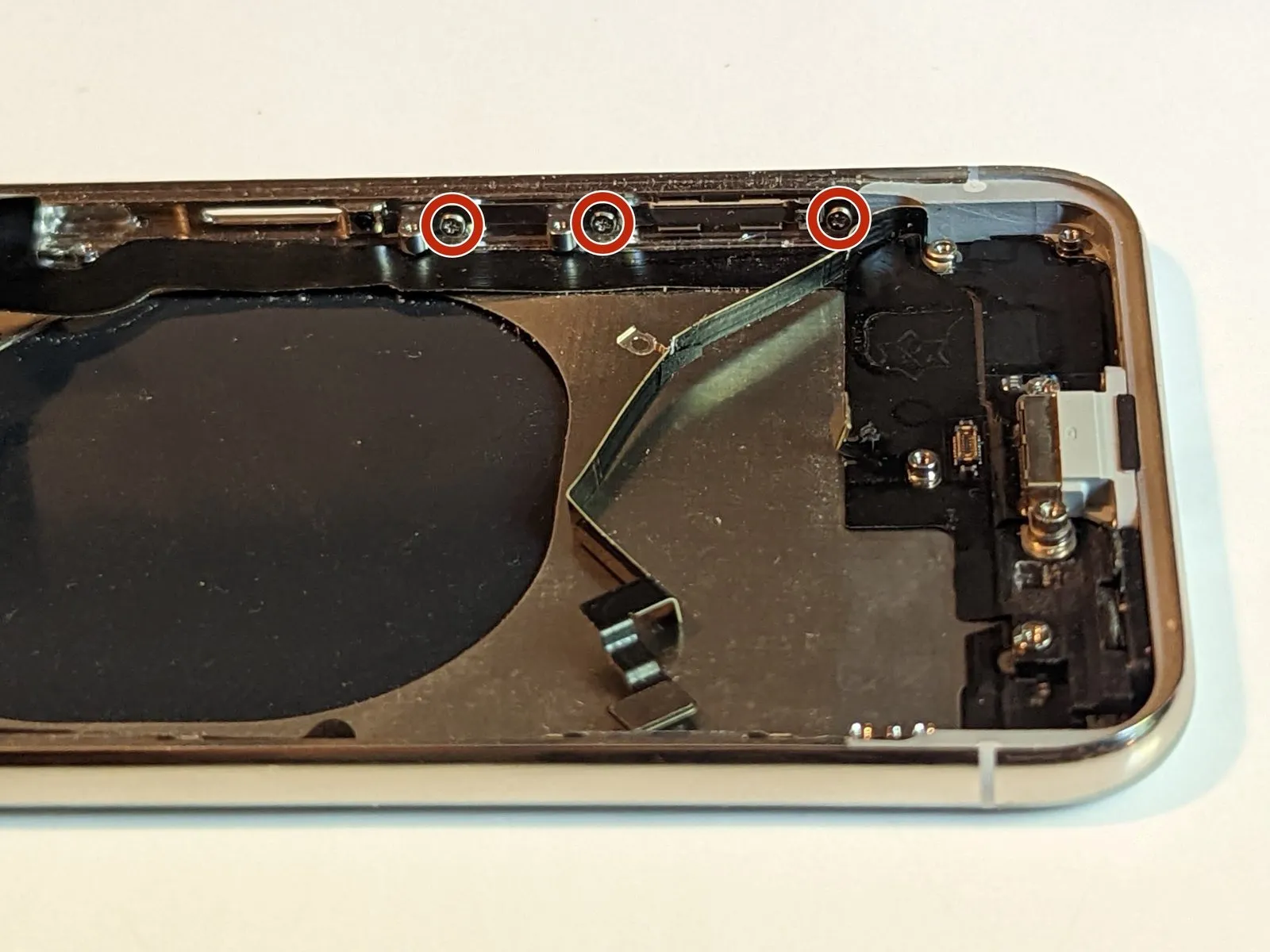
- Using the appropriate tool, detach the three.Use a Phillips screwdriver, size 1.5 mm.Secure the screen retainer in place.
- Carefully detach the securing retainer.
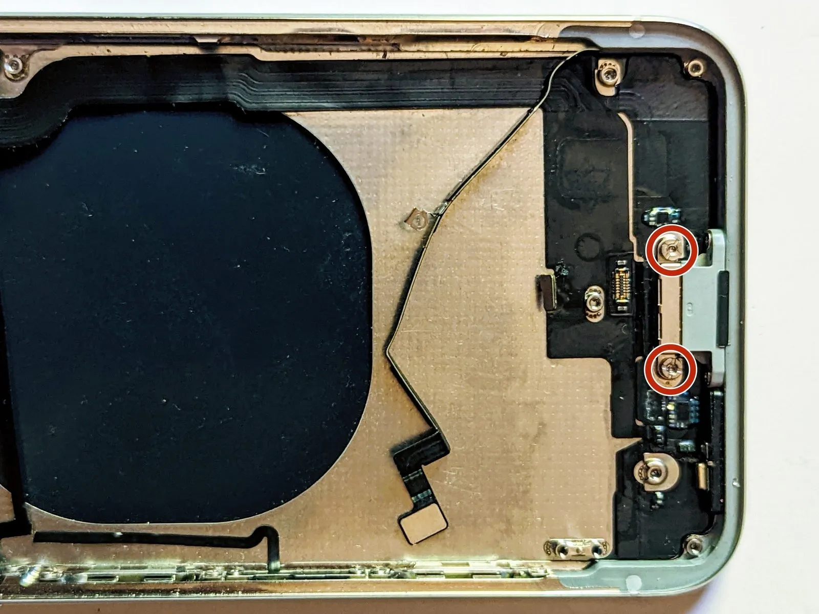
Step 75 | Lightning Connector

- Carefully detach theUse a screw with a 2.3 mm clearance height.Secure the barometric vent.
- To detach standoff screws, utilize a standoff screwdriver or a compatible bit.
- If a dedicated tool isn't available, a small flathead screwdriver can be carefully substituted; however, exercise heightened awareness to prevent slippage and potential harm to nearby parts.
Step 76
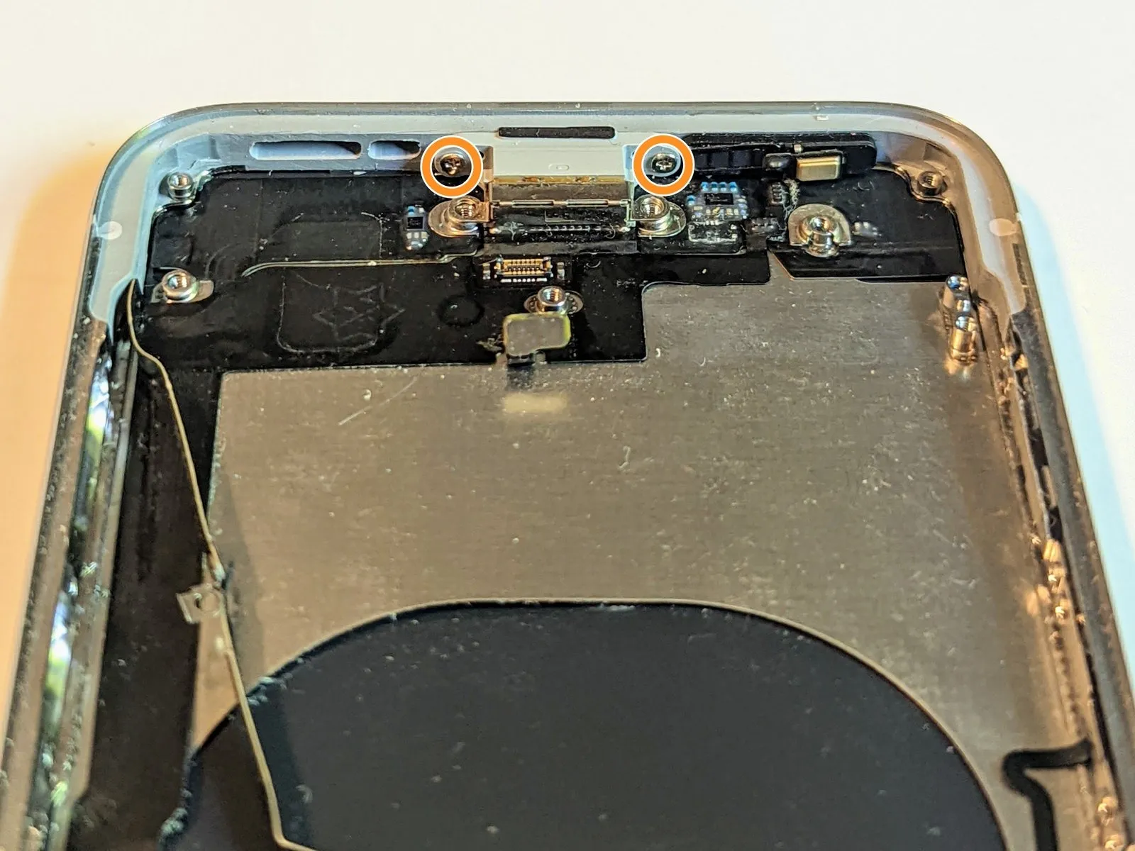
- Detach two.Use screws with a 2.6 mm length.Affix the Lightning connector to the rear case using the provided adhesive.
- Detach two.Use a Phillips screwdriver with a 2.9 mm tip.Secure the charging port in place against the case's lower surface.
Step 77

- Apply heat to the flex cable's edges where it meets the case, ensuring the temperature does not exceed 100°C using a heat gun or similar device.Apply warm air, using a hot air gun or hair dryer, to raise the temperature.Alternatively, apply warmth to the case's rear surface using an iOpener.
- Using a spudger, carefully lift the dock connector cable.
Step 78


Carefully lift the dock connector, maintaining its orientation.
Step 79

Carefully detach the dock connector.
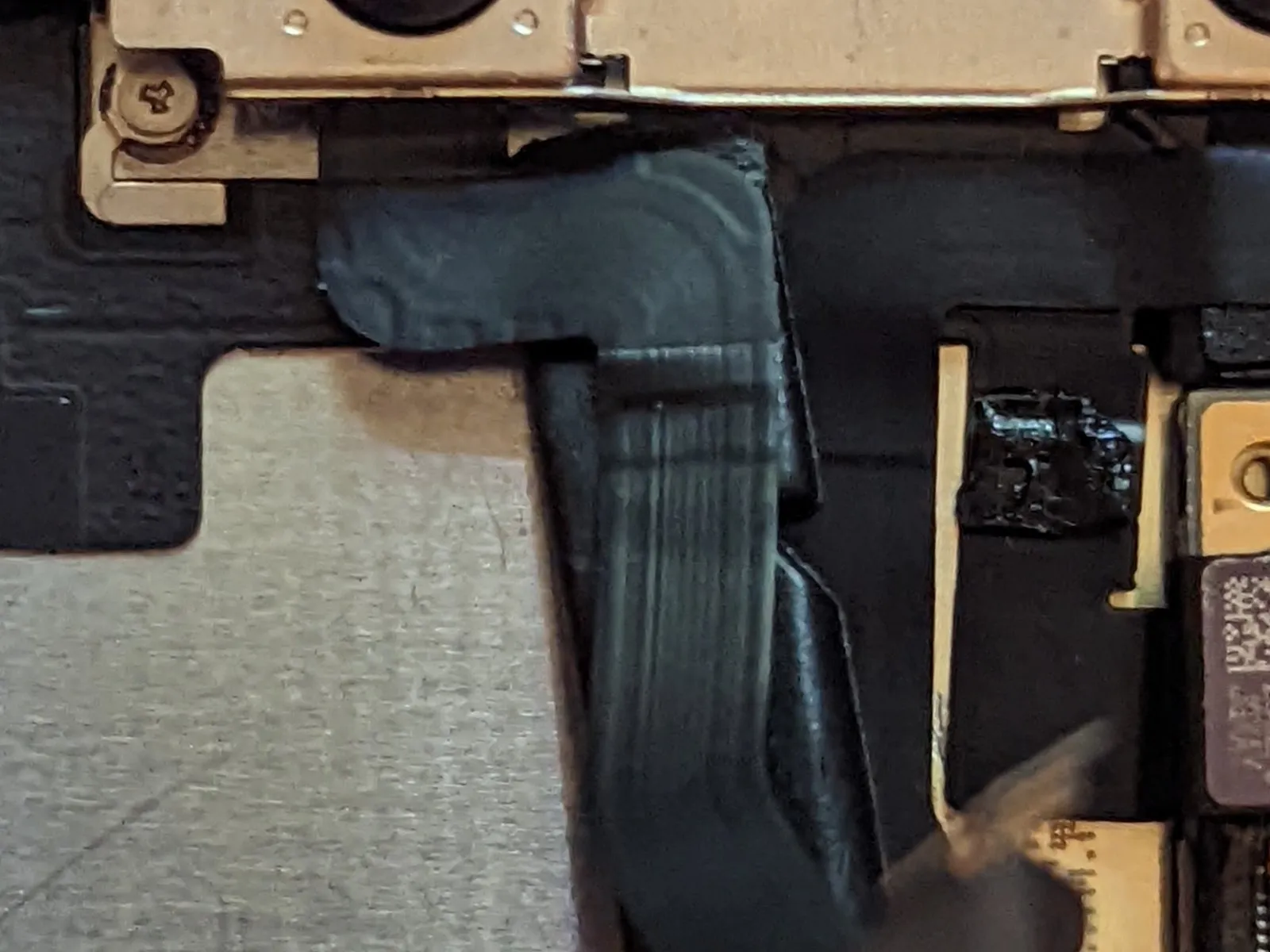
Step 80 | Interconnect Cable


- The interconnect cable is secured to the case solely by adhesive after the Lightning connector is detached.
- Apply heat using a heat gun, maintaining a temperature of 80-100°C, to loosen the adhesive securing the flex cable to the case.Apply warm air, using either a hot air gun or a hair dryer, to raise the temperature.Alternatively, apply warmth to the case's rear surface using an iOpener.
Step 81


Step 82
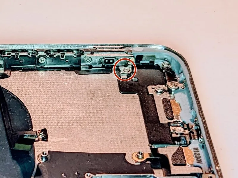
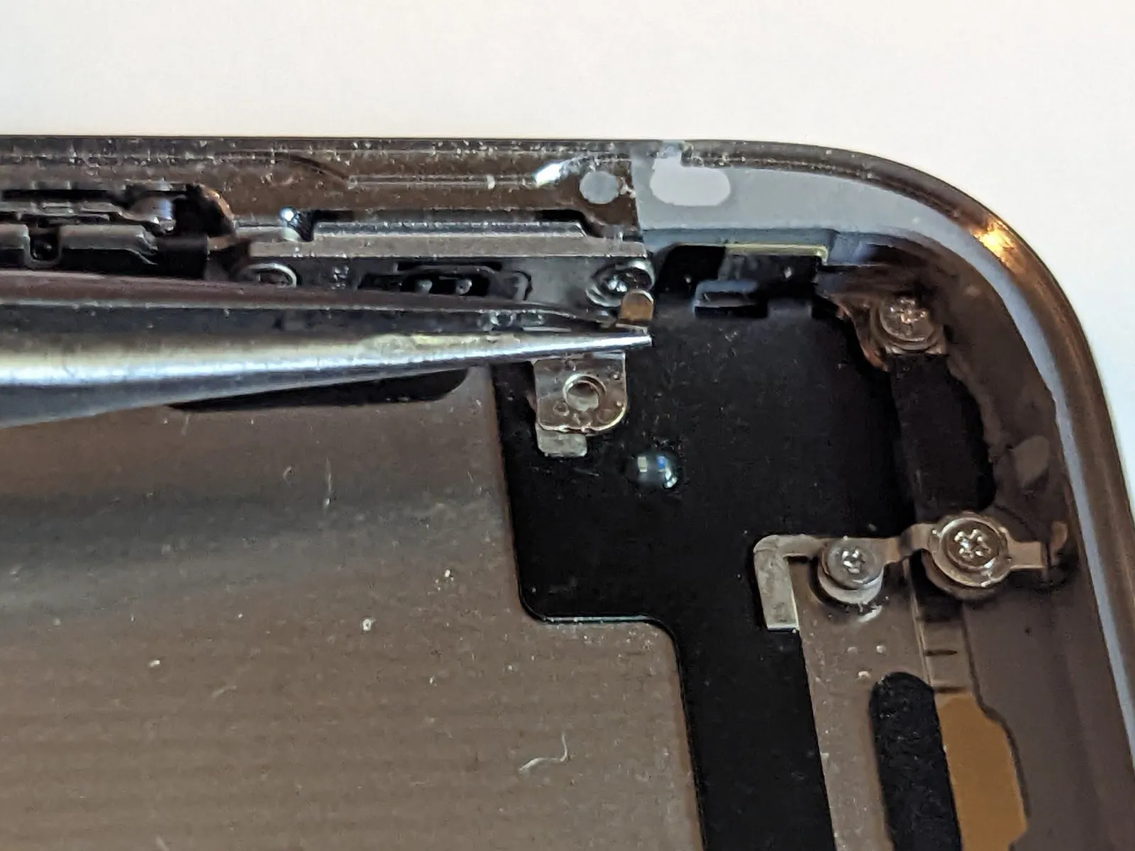
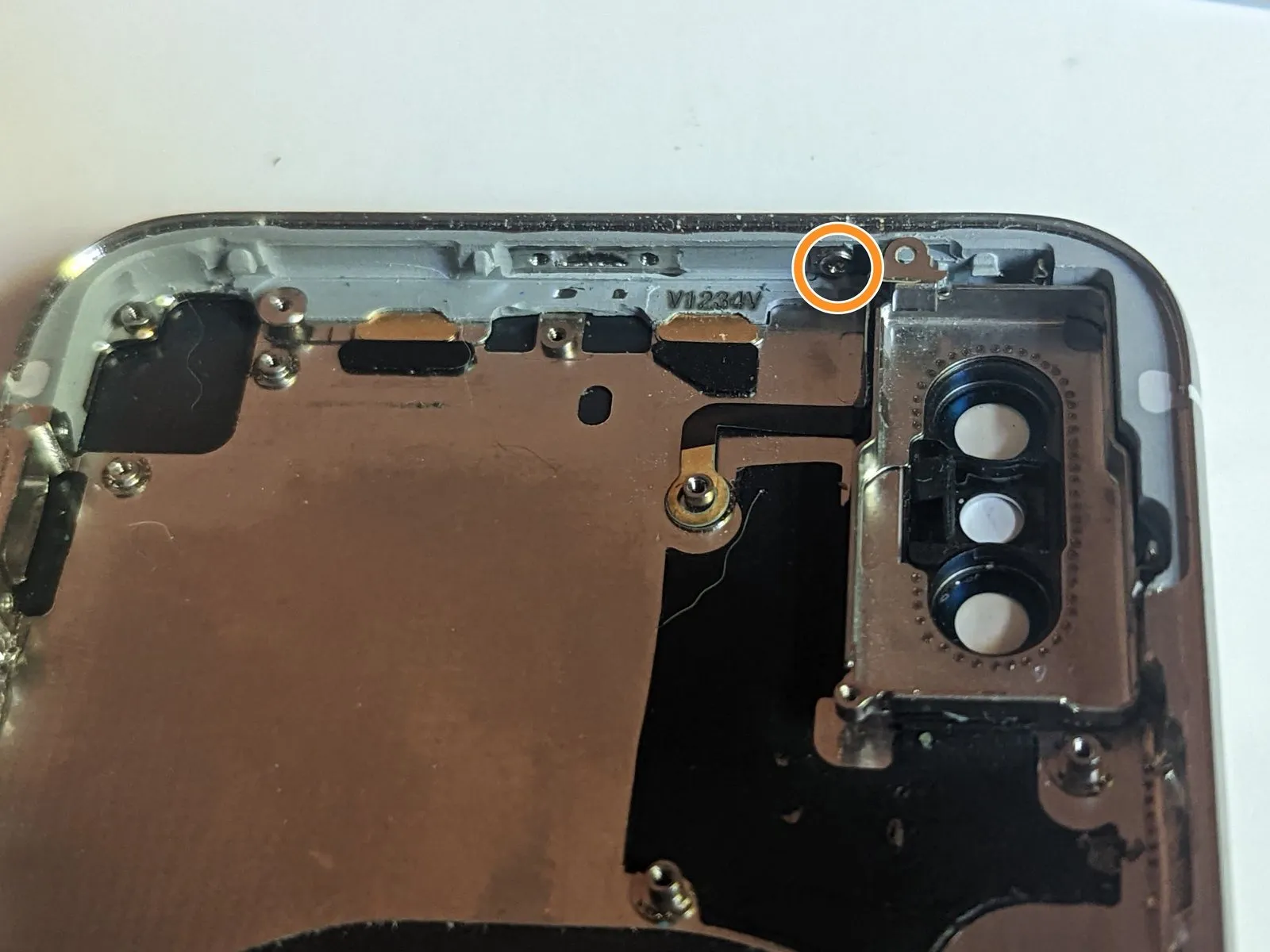
Step 83 | Upper Right Screen Retainer
Carefully lift the dock connector, angling it upwards and away from the surrounding components.
Step 84
- Begin the process by executing the action designated as "One."Use a Phillips screwdriver with a 2.1-millimeter tip..
- Begin the process by executing the action designated as "One."Use a Phillips screwdriver, size 1.9 mm..
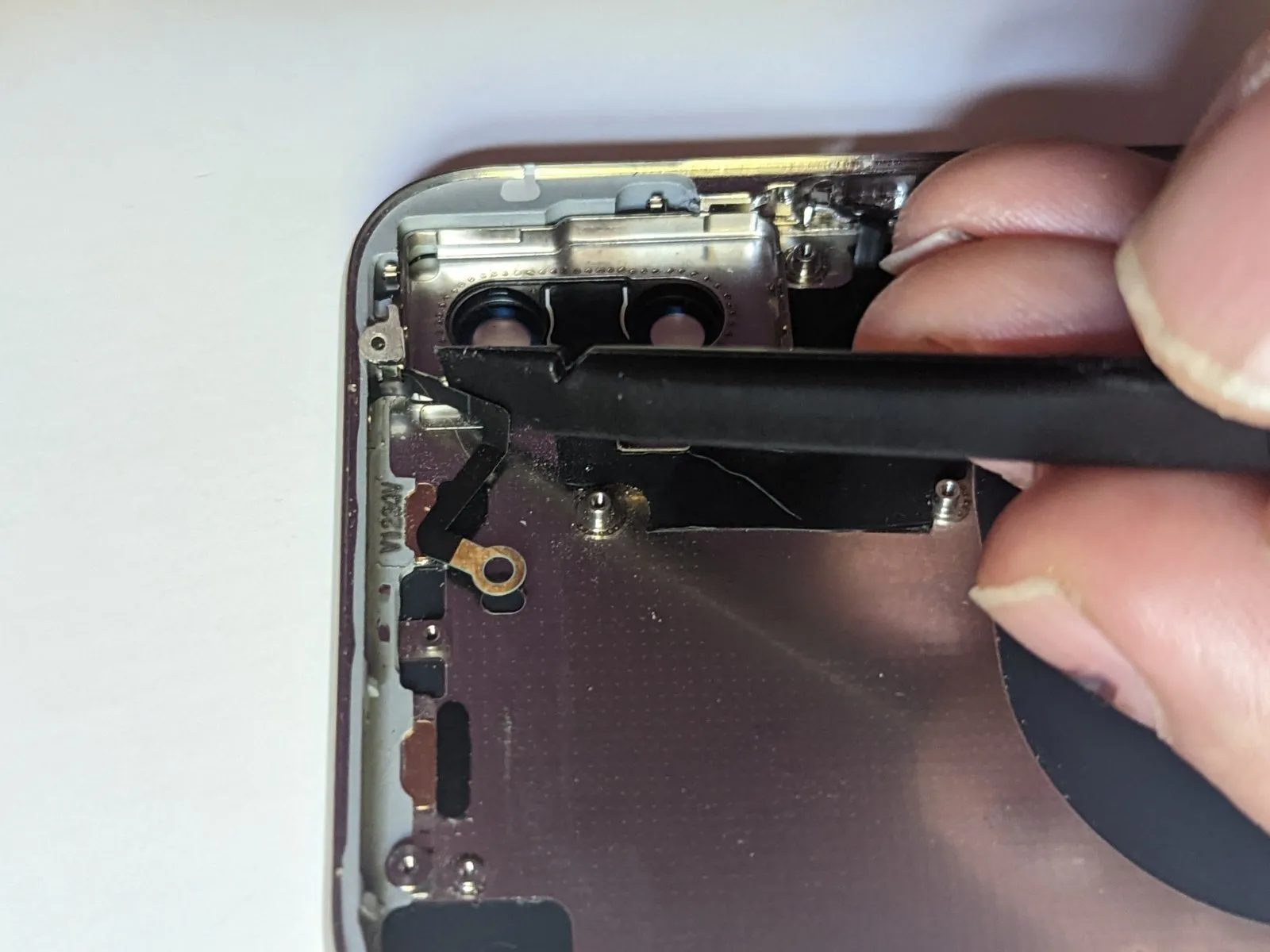
Carefully detach the screen retainer.
Ensure the retainer is positioned so it slides into place behind the black plastic component located at the end furthest from the power button.
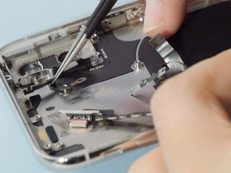
Step 85 | Power Button and Flash Cable
Step 86
Step 87
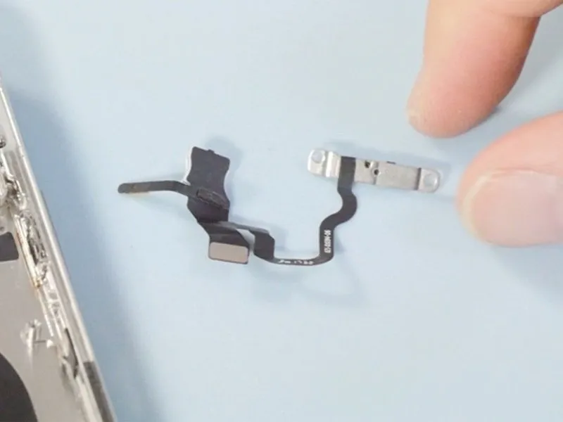

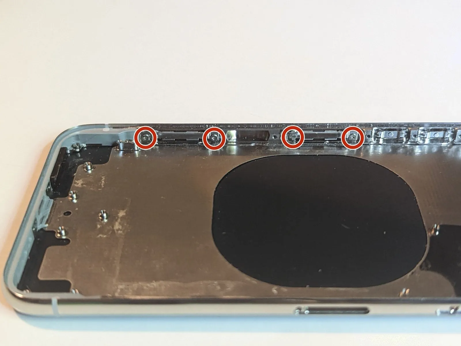
Step 88 | Volume Button Assembly
- Carefully detach the component, ensuring no damage occurs.Use a Phillips screwdriver, size 1.4 mm.Maintain contact with the grounding tab.
- Carefully detach the grounding tab.
- Ensure the tab is positioned as it was initially, paying close attention to its alignment during reassembly.
Step 89

- Using a screwdriver, detach the six screws that hold the buttons in place.
Use Phillips head screwdrivers with a 1.5 mm tip..
Use two screwdrivers with a 1.9 mm Phillips head..
Use a Phillips screwdriver, size 2.4 millimeters..
Use a Phillips screwdriver with a 1.7 mm tip..
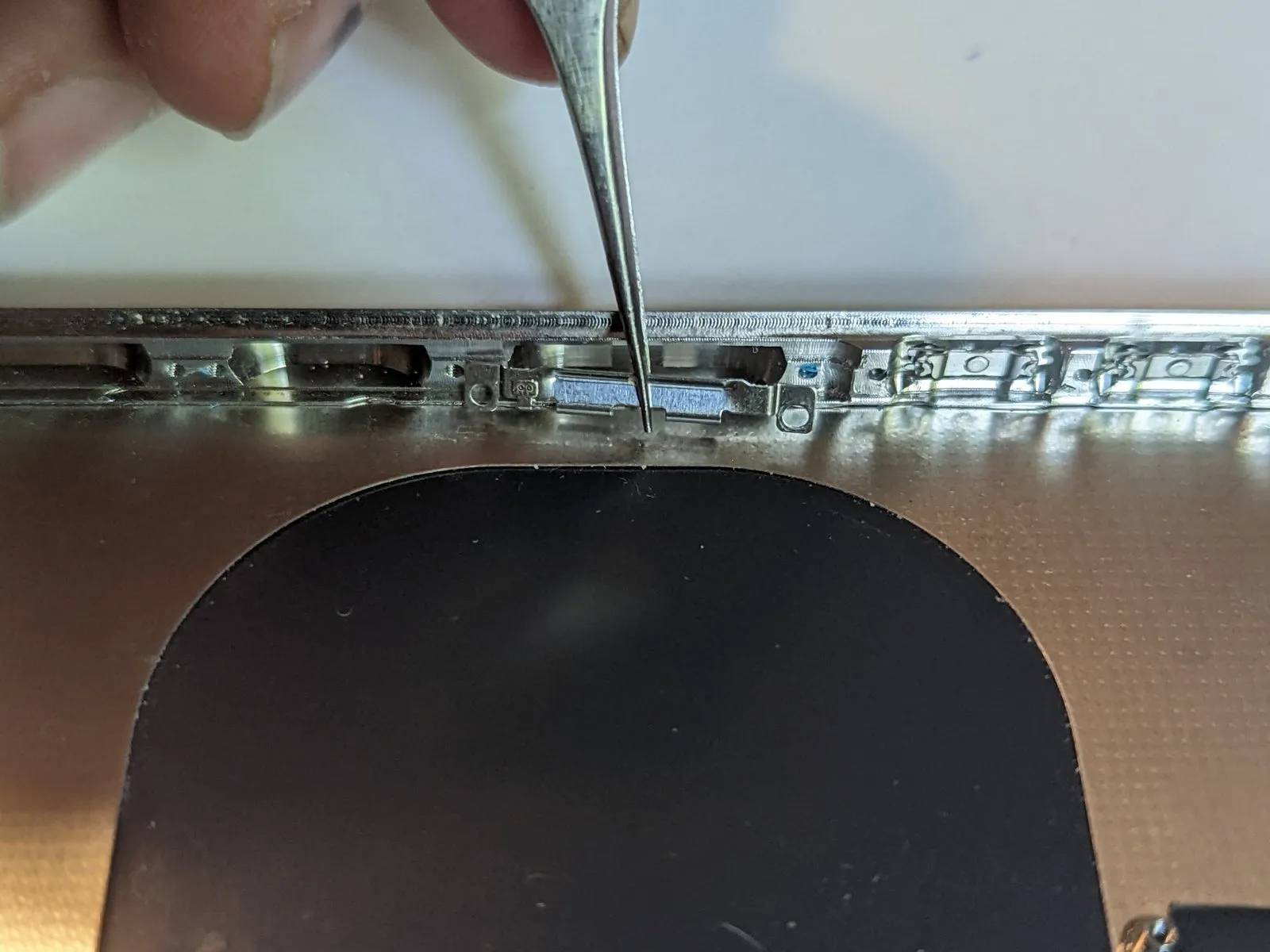
Step 90

- Carefully separate the ring/silent switch from the case's exterior.
Carefully separate the flex cable from the case's underside using a spudger.
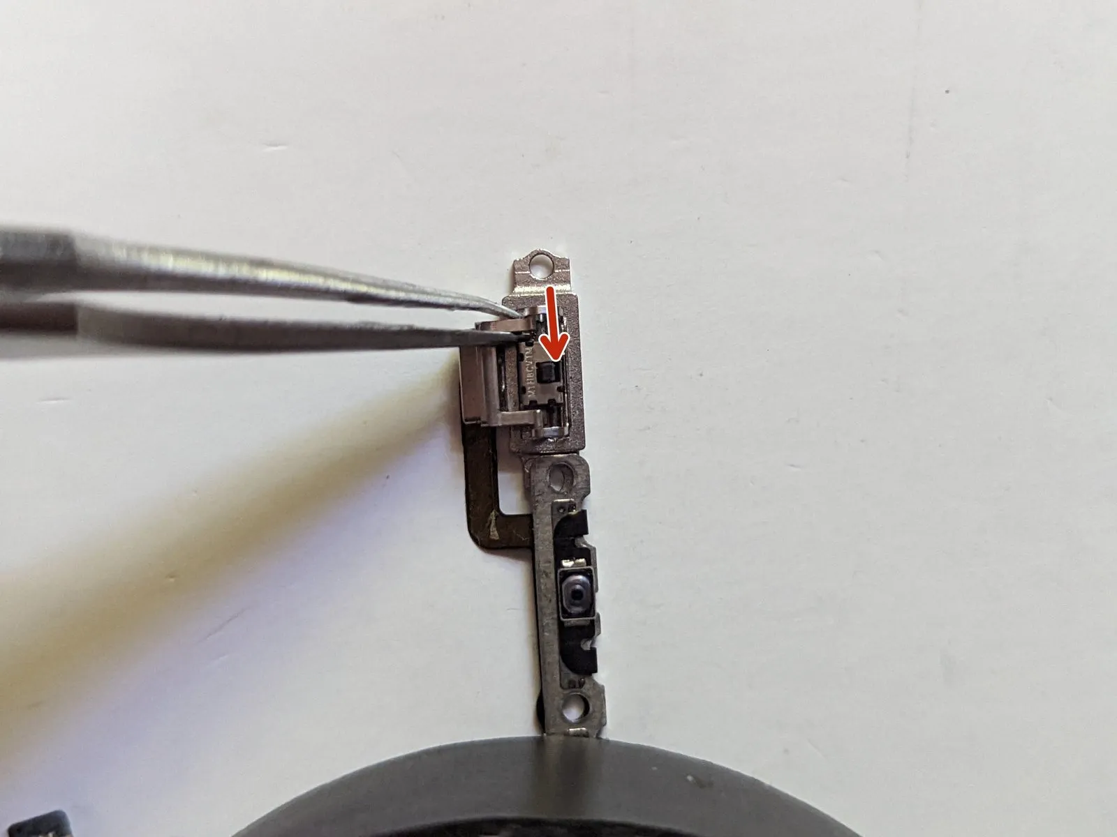
Step 91
- To facilitate adhesive separation, apply warmth to either the device enclosure using an iOpener or the flex cable with a hot air gun or hair dryer.
Carefully disconnect the button cable by separating it from its connection.
To prevent damage, exercise utmost caution when detaching this cable from the button/charging coil assembly if you intend to reuse it; the cable is exceptionally thin and delicate. Proceed deliberately, minimizing any strain applied to it.
Using tweezers to secure the cable, carefully insert the spudger between the cable and the case, then gently slide it to separate them.
Step 92 | Charging Pad / Volume Button Assembly

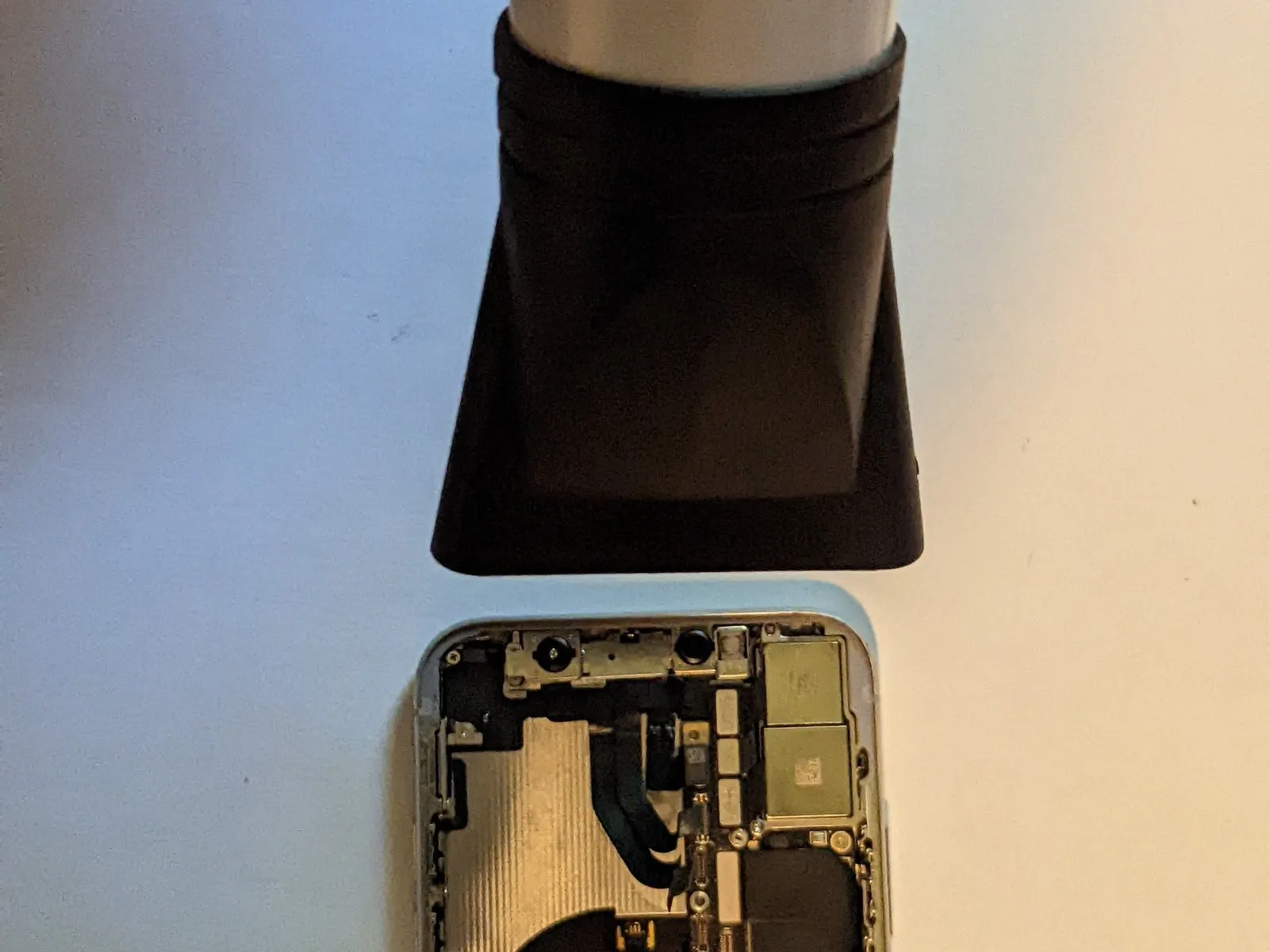
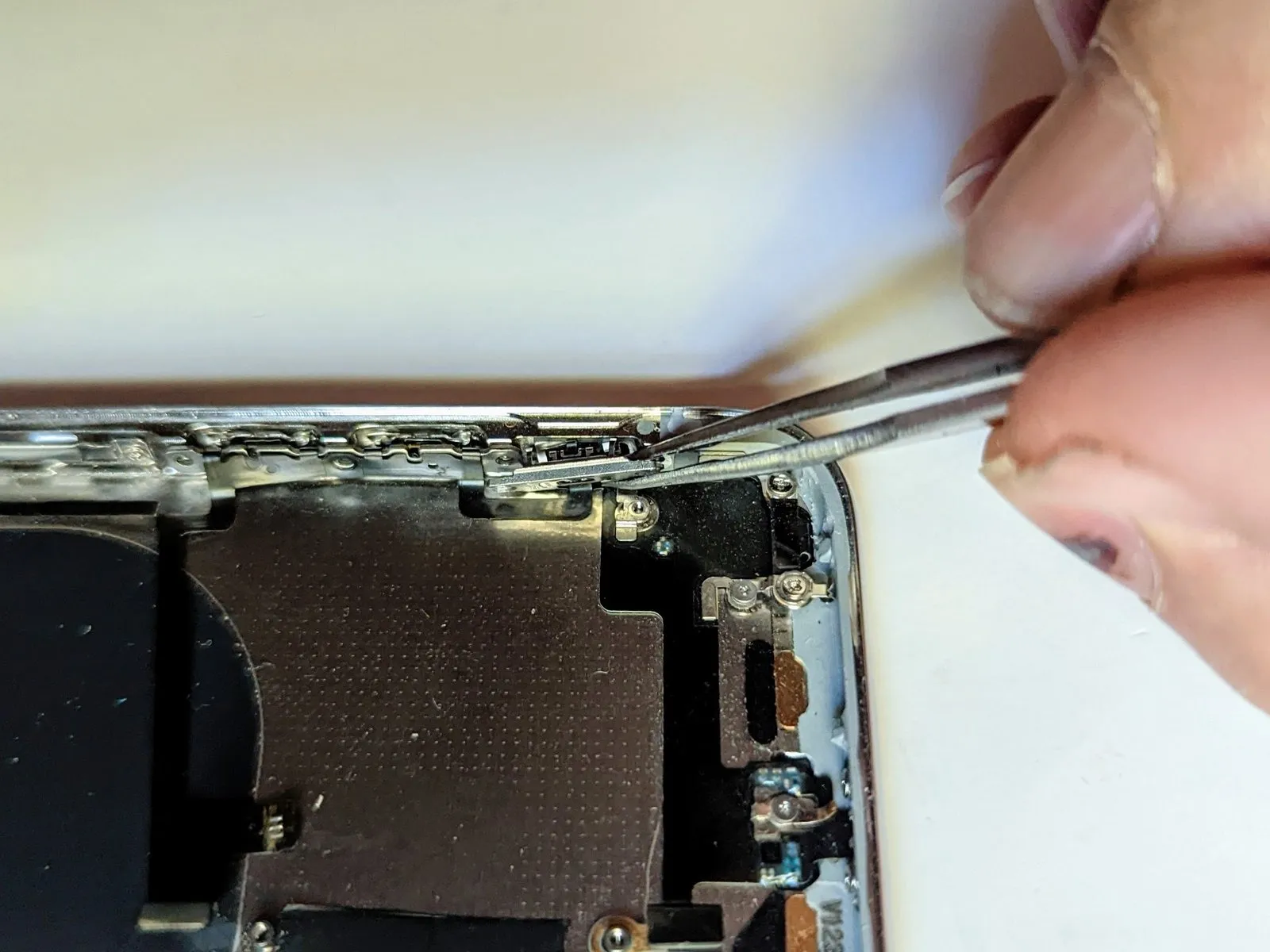
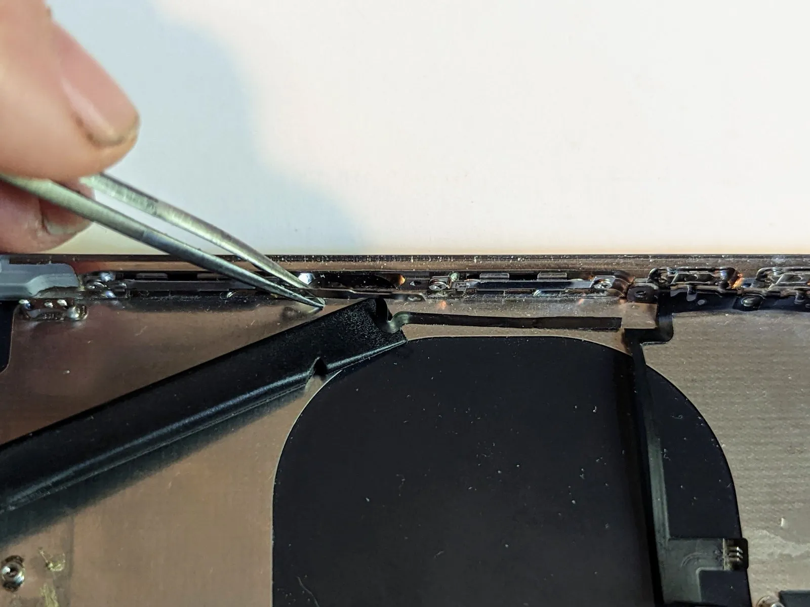
- To loosen the adhesive securing the rear casing, apply heat to the phone's back surface using an iOpener, a hot air gun, or a hair dryer.
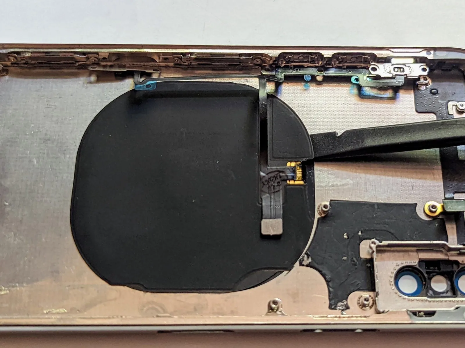
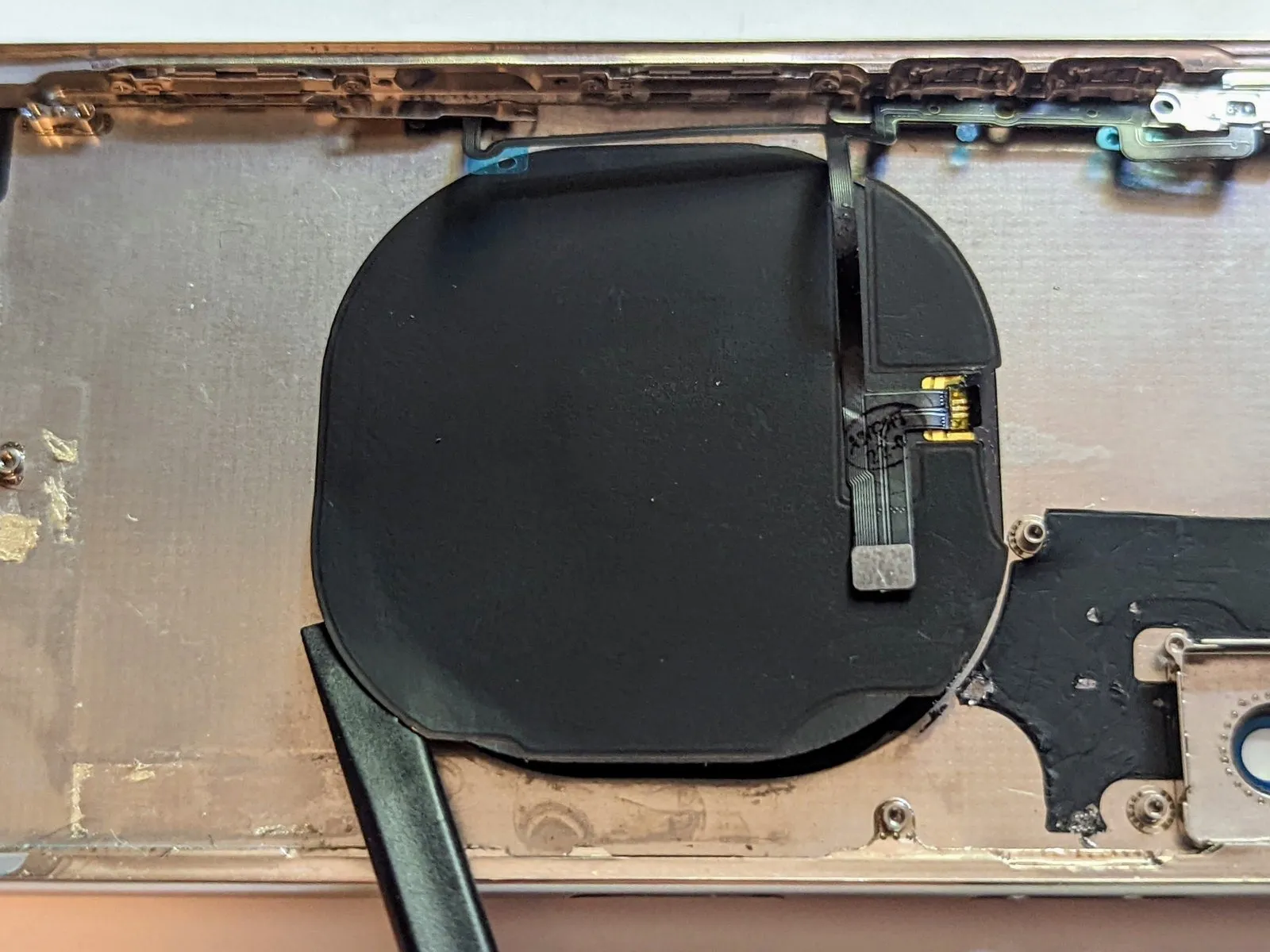
Carefully detach the wireless charging coil.
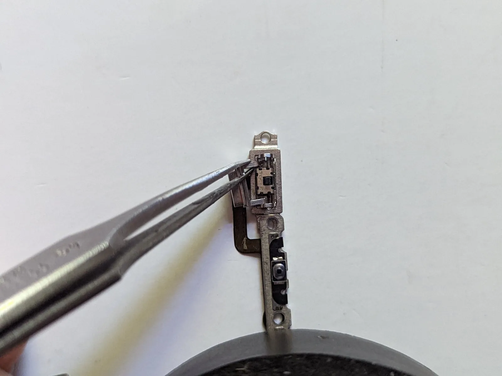
Step 93

- Detach the component from its surroundings.
Step 94 | Move the Ring/Silent Switch

- When substituting the button assembly, carefully move the ring/silent switch from the removed part to the replacement.
Refer to the dedicated iPhone X Power and Audio Exterior Buttons guide for detailed procedures on detaching the external switch component from the button assembly.
Step 95 | WiFi Antenna
- Carefully detach the component, ensuring no damage occurs.Use a Phillips screwdriver, size 1.4 mm.Maintain contact with the initial grounding tab.
Carefully detach the grounding tab.
Ensure the tab is positioned as it was originally, paying close attention to its alignment during reassembly.
Step 96

- Detach the four fasteners.Use Phillips head screwdrivers sized 1.5 mm to tighten or loosen..
Step 97
- Detach two.Use a Y000 screwdriver to loosen 1.1-millimeter screws..
- Detach the two tabs designated for grounding.
- Ensure the tabs are positioned as they were originally, paying close attention to their alignment when putting everything back together.
Step 98

- Using a heat gun, apply warmth to the rear housing to soften the adhesive.Use a specialized tool like an iOpener to gently apply heat around the perimeter of the device's casing.Apply heat to the WiFi antenna using a hot air gun or hair dryer.
- Carefully detach the WiFi antenna from the enclosure using a spudger.Use a plastic pry tool to gently separate..
Step 99
Carefully detach the WiFi antenna, ensuring no damage occurs to the connector or surrounding components.
Step 100 | Bluetooth Antenna
- Carefully detach the component, ensuring no damage occurs.Use a Phillips screwdriver with a 2.3 mm tip.Attach the antenna to the rear camera frame, ensuring a firm connection.
- Carefully detach the component, ensuring no damage occurs.Use a Phillips screwdriver with a 1.5 mm tip.Affix the antenna to the enclosure, ensuring it is firmly attached.
Step 101

- Detach the cable from the rear case connector by raising its end.
- Using a spudger, carefully separate the cable from the rear camera housing.Use a plastic pry tool to gently separate..
- Carefully detach the component, ensuring no damage occurs.The wireless communication module, specifically the Bluetooth antenna,.
Step 102 | Front Panel Screen Retainers

- Using a Phillips head screwdriver, detach the four screws.Use a Phillips screwdriver sized for 1.5 mm screws.Securely grasp the two left-side screen retaining clips.
- Detach the two fasteners.
Step 103 | Remove the Ring/Silent Switch
- Move the switch to the left position.
- Using fine-tipped tweezers, carefully move the switch's upper arm downwards to release the retaining mechanism.
- To remove it, shift the component laterally until it disengages from its mounting point.
- Ensure the orange stripe faces upward during reassembly, referencing the provided image for correct orientation.
Step 104 | Remove the Button Spring Clips
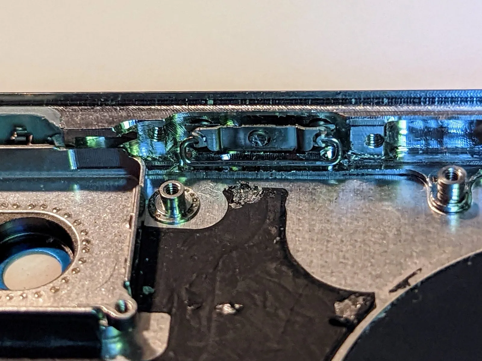
To prevent electric shock or potential injury, always disconnect the power supply and allow the device to cool completely before proceeding with any maintenance or repair procedures.To avoid potential difficulties and damage, review the video detailed in the introduction prior to disassembly; the button removal process is complex and can be challenging, therefore, closely observe and replicate iPhoneRepairGirl's techniques.
To prevent the button from protruding during clip and retainer removal, apply outward pressure with a finger against its exterior surface, pushing it inward within the frame.
Rotate theSecure the component with the spring clip.Rotate the component until it achieves a 90-degree angle.
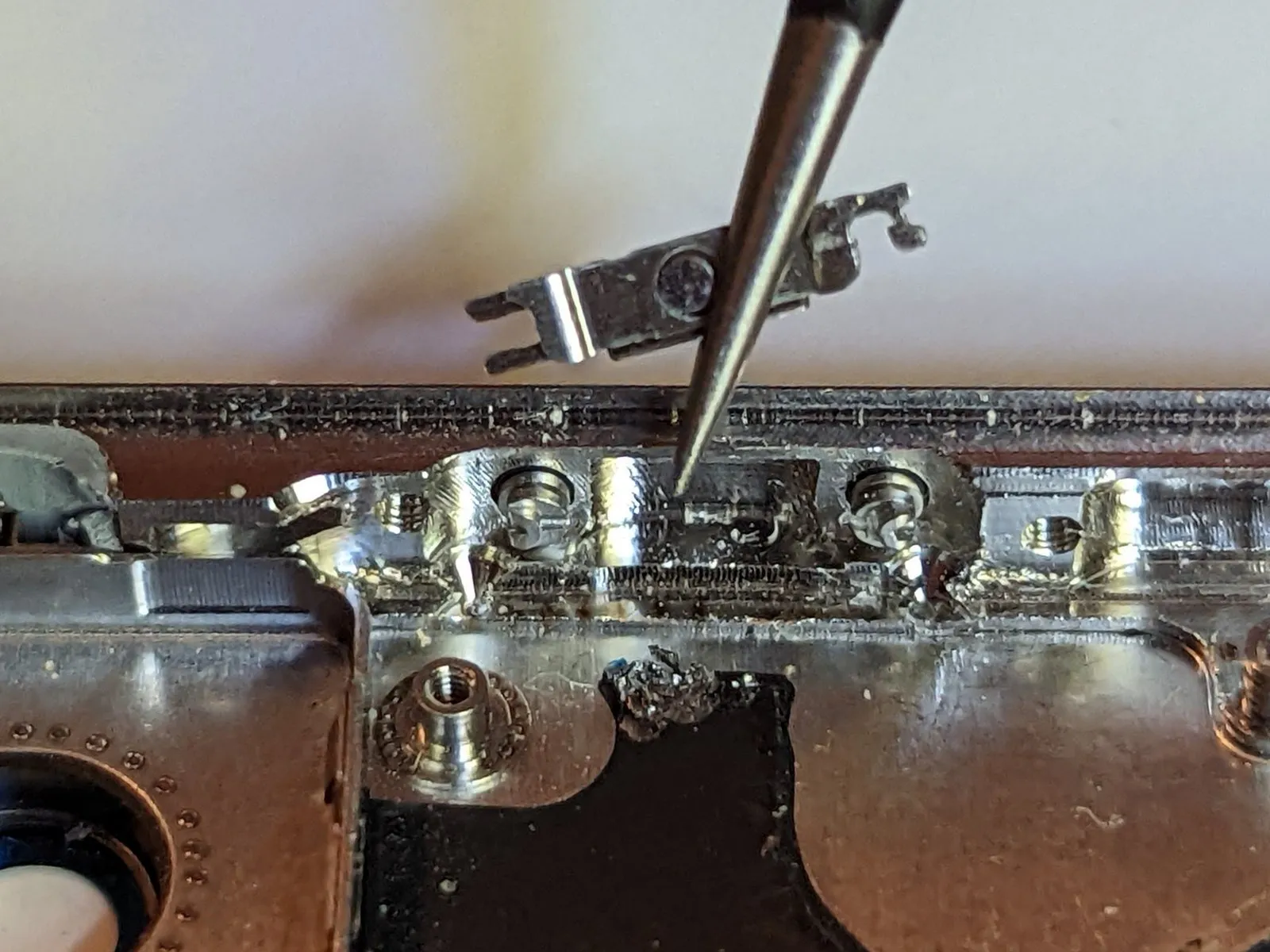
Step 105


- Using tweezers, securely hold one end of the spring clip.
To release the clip, grasp its terminal end and apply steady traction until it disengages from the button.
Gently pivot the clip away from the button's surface.
To release the opposite end, move the clip in the reverse direction.
Detach the spring clip.
Perform the same procedure on both the increase and decrease volume controls.
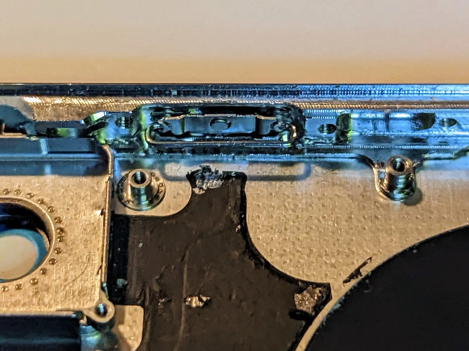
Step 106 | Remove the Button Retaining Plate


- Using a prying tool, lift the right-hand portion of the retainer to an angle of approximately 20 degrees.
- Using a consistent, straight motion, disengage the retainer from the button, ensuring it moves directly outward.
Thoroughly clean again, then repeat the process.
Ensure complete seating of each retainer during reassembly, verifying that the lower space between the button's surfaces remains consistent along its entire length.
Step 107 | Remove the Volume and Power Buttons
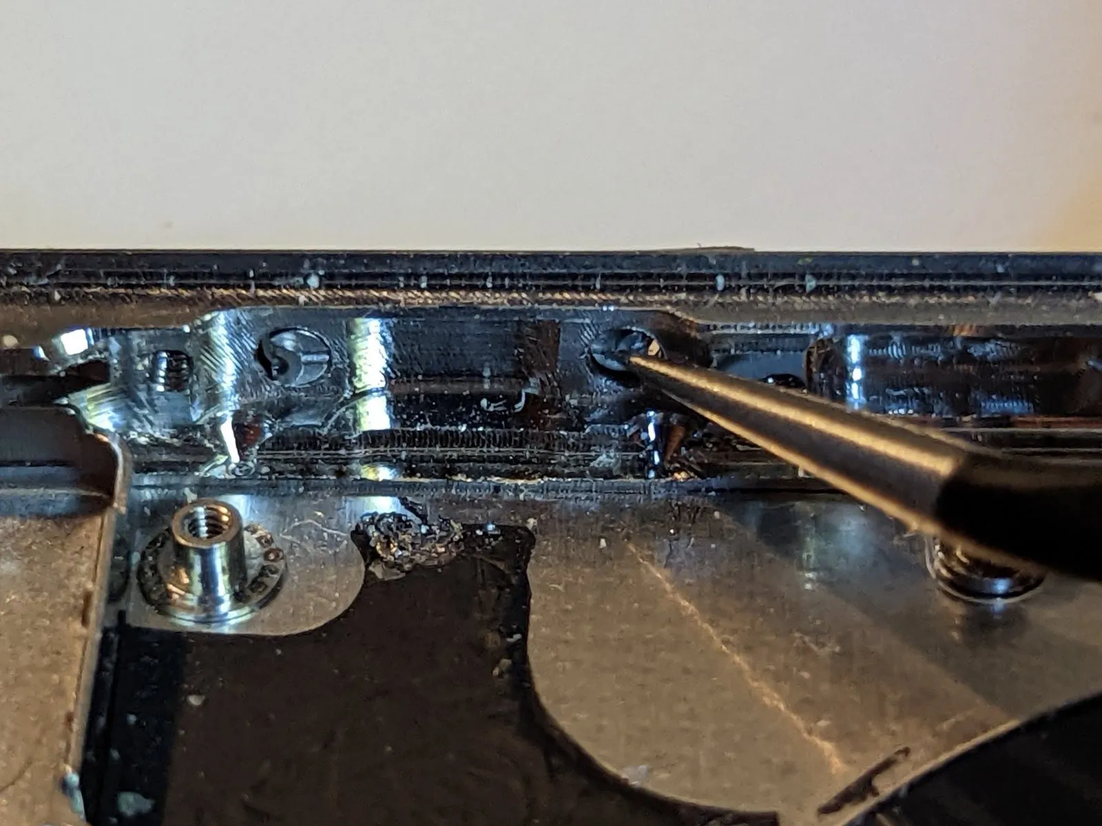
- Should external access to the button be unavailable, extract the pins from within the case's interior.
- Carefully detach the button, ensuring no damage occurs to surrounding components.
Apply the cleaning procedure again to each of the other buttons.
Review the assembly video prior to reattaching the buttons; the reassembly process is more complex than disassembly, requiring careful attention and patience to ensure proper fit.
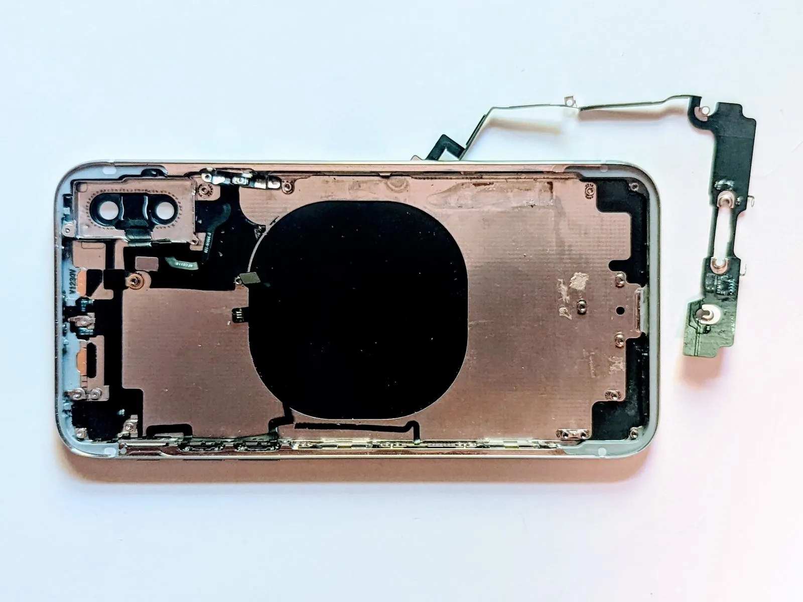
Step 108 | Rear Case
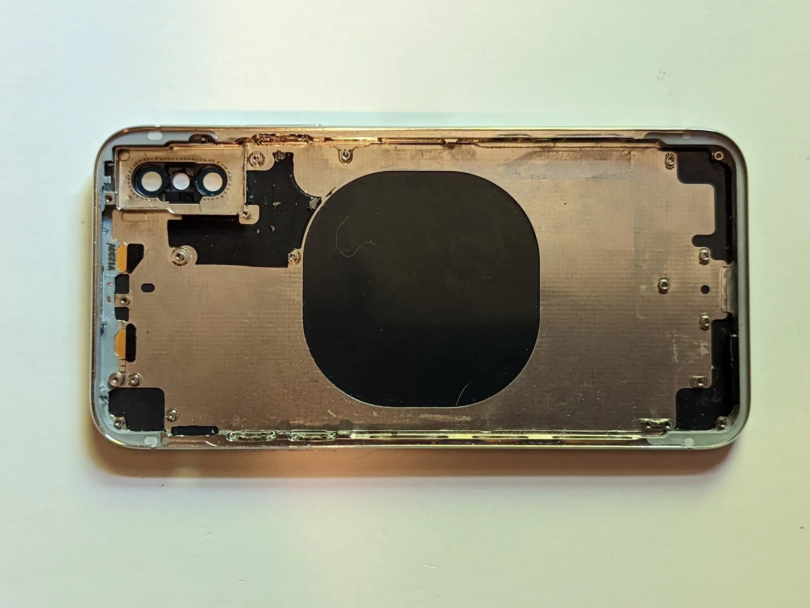
- Every component has been removed from the case.
- Carefully install the components into the replacement housing.