iPhone X Unresponsive Touchscreen Repair
Prior to commencing any repair work, it is essential to disconnect the device from all electrical power to prevent potential hazards.
- Necessary Tools:A Phillips head screwdriver is needed for this procedure.
Consult the device's user documentation for detailed specifications related to your particular model and supplementary safety guidelines.
Step 1 | Screen


- Initiate the device's power sequence by depressing the power button; successful activation is indicated by normal operation.The device's touch screenexhibits a lack of response to touch input.
- To proceed with diagnostics, deactivate the device and disassemble it, ensuring disconnection of the battery and subsequent removal of the display assembly.
- Following disassembly, extract the motherboard; the initial diagnostic step involves inspection of theTouch ID Flexible Printed Circuit (FPC) connector, designated J5800Perform a diode mode measurement on J5800; a reading of Open Loop (OL) on Pin 22 signifies a circuit discontinuity on the associated circuitry.
Step 2
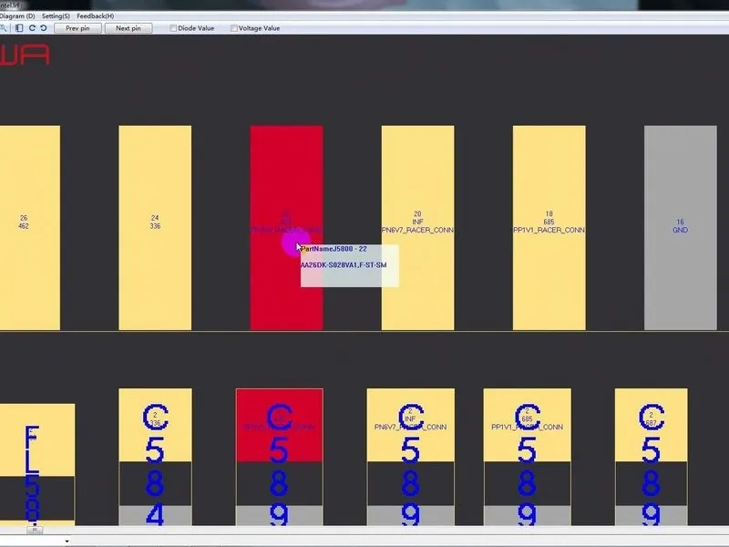

- An inductor, identified as FL5893, is visible within the circuit's design.The component in question is the inductor, FL5893; our troubleshooting will begin with this element.Initially, use tweezers to carefully clear any surrounding sponge material from connector J5800.
- Employing diode mode, perform a measurement between Pin 1 and Pin 2 of FL5893; a reading of 0 indicates the presence of a short circuit.Based on the measured value, the inductor, FL5893, appears to be functioning correctly.The circuit's path extends to the third space PCB, necessitating motherboard separation for inspection of that specific board.
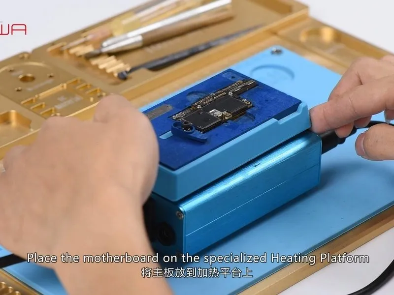
- Position the motherboard onto the designated Heating Platform; allow the platform's temperature to reach 160°C, then carefully lift the upper layer using tweezers.
Step 3

A visual inspection reveals numerous detached solder connections on the third space PCB, alongside significant deformation of the motherboard itself. Based on these observations, the motherboard appears beyond economical repair.