Repair an iPhone X That Won't Charge
Prior to commencing any repair work, it is essential to disconnect the device from all electrical power supplies.
- Necessary Tools:A Phillips head screwdriver is needed.
Consult the device's user manual for detailed specifications related to your particular model and for supplementary safety guidelines.
Step 1 | Won't Charge

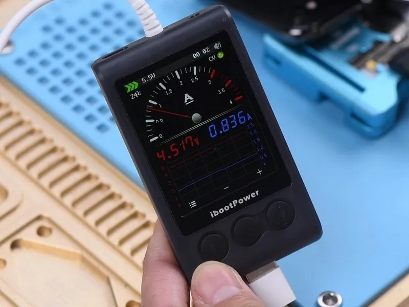
- To begin the repair process, we will install the motherboard and perform an initial functionality test, confirming that the device powers on as expected.
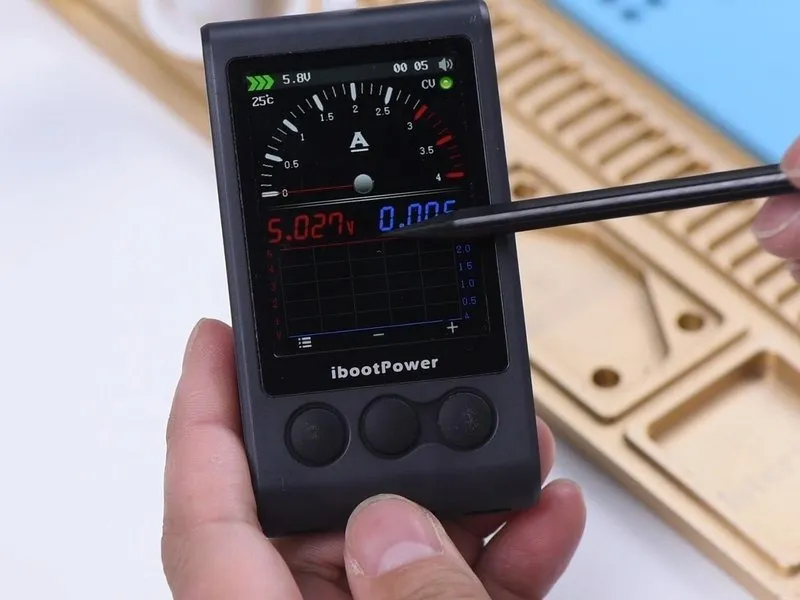
- Connecting the charging cable results in the display of the lightning bolt icon, but the ammeter indicates an absence of charging current.
- This observation suggests the motherboard recognizes the power adapter, yet the device is unable to initiate the charging sequence.
Step 2

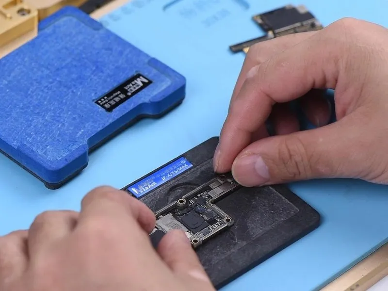
- Given that the device's casing, power cell, and the flexible connector responsible for charging have been verified as functional, troubleshooting efforts should now concentrate on the charging circuitry located on the main circuit board.
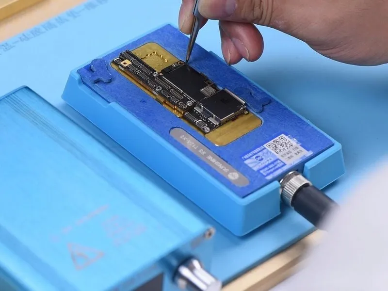
- Initially, detach the upper assembly from the lower assembly; to facilitate this process, position the motherboard upon the heating platform and secure a screw within the designated screw aperture on the board.
- Apply heat to the motherboard for a duration of 2 minutes utilizing the heating platform, maintaining a temperature of165°C.
Step 3


- Perform a diode mode test on Pin 2 and Pin 3 of the J3200 battery connector, confirming a standard reading.
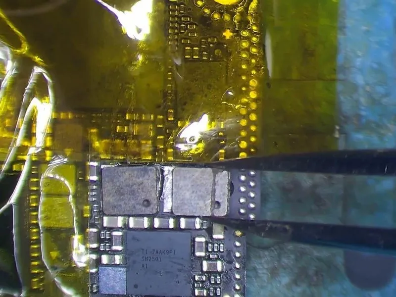
- Proceed with measurements TIGRIS_LX across the charging IC, designated U3300, and the transistor Q3350. An atypical reading of 250mV was observed, diverging from the expected 0mV. This deviation indicates that TIGRIS_LX is exhibiting an open circuit condition.
Step 4


- Inductors L3341 and L3340 are linked sequentially within the circuit's design. A break in the circuit suggests a potential issue such as incomplete soldering or physical damage to these components, necessitating their replacement with functional inductors.
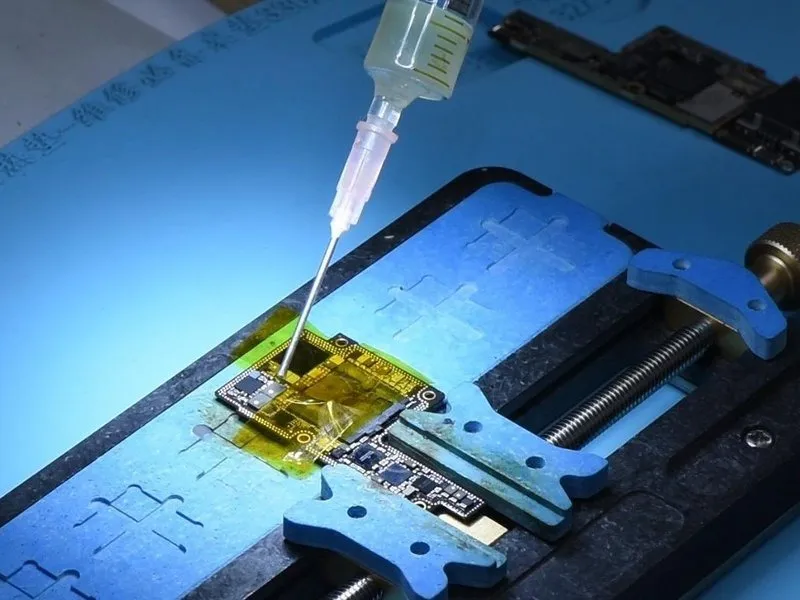
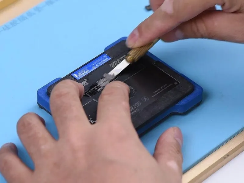
- Secure the upper circuit board layer to the designated PCB holder and apply high-temperature resistant tape to protect surrounding components.
- Apply heat utilizing aQUICK 990AD Hot Air Gunat a temperature of 300°C, employing an airflow rate of 3.
- Carefully eliminate the black adhesive material surrounding the two inductors.
- After the adhesive is removed, apply a suitable solder flux to the surfaces of the two inductors. Then, apply heat utilizing aQuick 990AD Hot Air Gunat a temperature of 360°C, maintaining an airflow rate of 3.
Step 5


- Utilizing a pry knife, gently separate the two inductors from their position.pry knife.
- Spread a moderate amount of medium-temperature solder paste across the two bonding pads.365°C.
- Subsequently, remove any residual black adhesive from the bonding pad surfaces.
Step 6
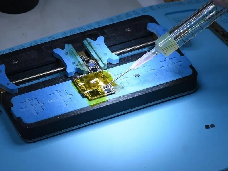

- Further application of paste flux is necessary on both bonding pads.
- Carefully position the two inductors and secure them with solder using aQUICK 990AD Hot Air Guna temperature of360°Cand an airflow setting of 3.
- Following the soldering process, utilize PCB cleaner for cleaning. Subsequently, perform a diode mode measurement across TIGRIS_LX, specifically between U3300 and Q3350; a typical reading is 0.
Step 7

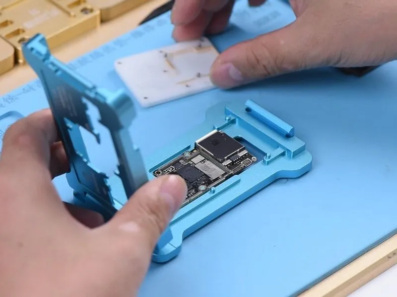
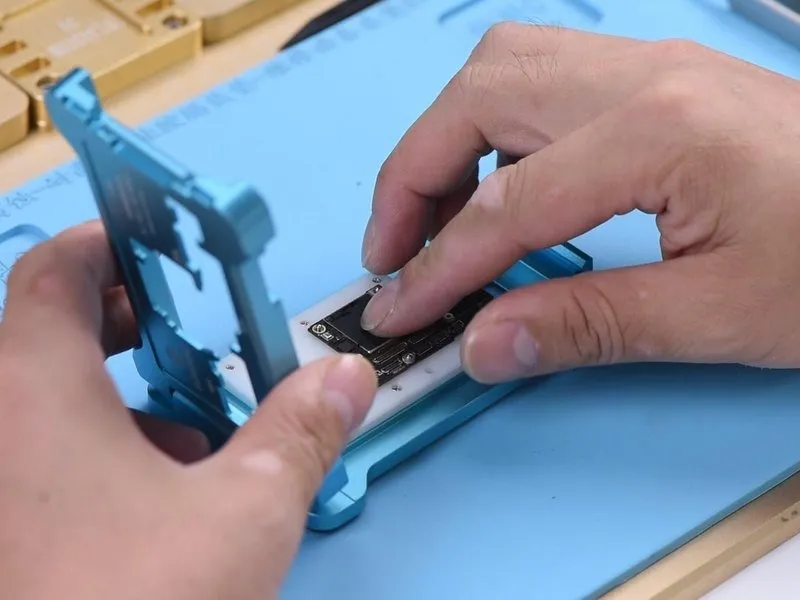
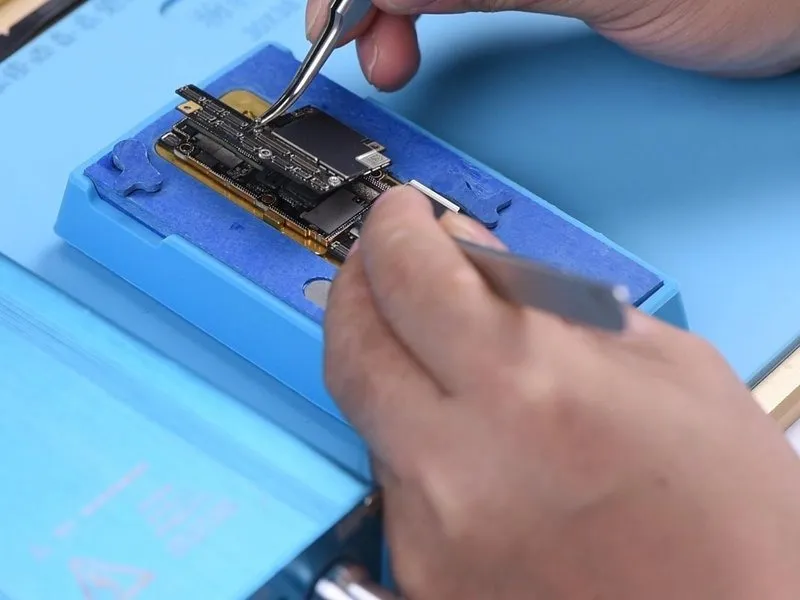
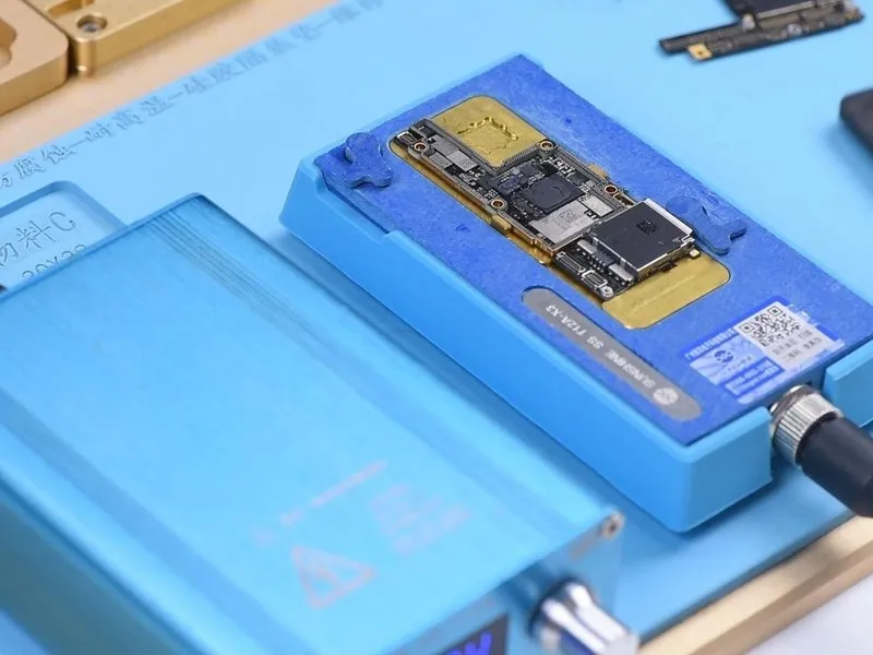
To proceed, secure both the upper and lower layers to the testing fixture for evaluation purposes.
- Begin by thoroughly cleaning the bonding pad surface.
- Subsequently, affix the upper layer and the lower layer to the testing fixture.
Step 8
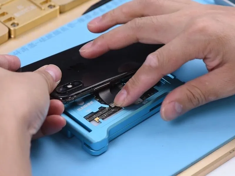

- Establish a connection for the charging port flex cable.
- Subsequently, connect the display panel and the battery.
- Introduce the charging cable into the device; observe the charging current displayed on the ammeter, which registers as860mA, signifying a standard charging process for the mobile phone.
Step 9

- Following this, the subsequent step involves joining the two layers via soldering.
- Prior to joining, the lower layer requires reballing; to accomplish this, position it within the reballing mold and ensure the BGA Reballing Stencil is correctly situated.
- Subsequently, place the mold onto the base, as the magnetic properties of the base ensure a secure adherence of the stencil to the lower layer.
- Afterward, apply a thin layer of low-temperature solder paste onto the stencil, then carefully remove any surplus paste utilizing a lint-free wipe.
Step 10

- Following the reballing procedure, detach the mold from the substrate and eliminate thereballing stencil.
- Establish a temperature of165°Con the lower layer using the heating platform. After the solder balls have fully formed their shape, deactivate the heating platform.
- Allow a cooling period of 5 minutes. Introduce a thin layer ofBGA Paste Fluxonto the bonding pad and carefully align the upper layer.
- Subsequently, activate the heating platform, allowing the temperature to reach165°Cand maintain the heat for an additional 2 minutes.
Step 11

- Deactivate the power supply and allow a cooling period of 5 minutes. Subsequently, detach the motherboard from the heating surface.
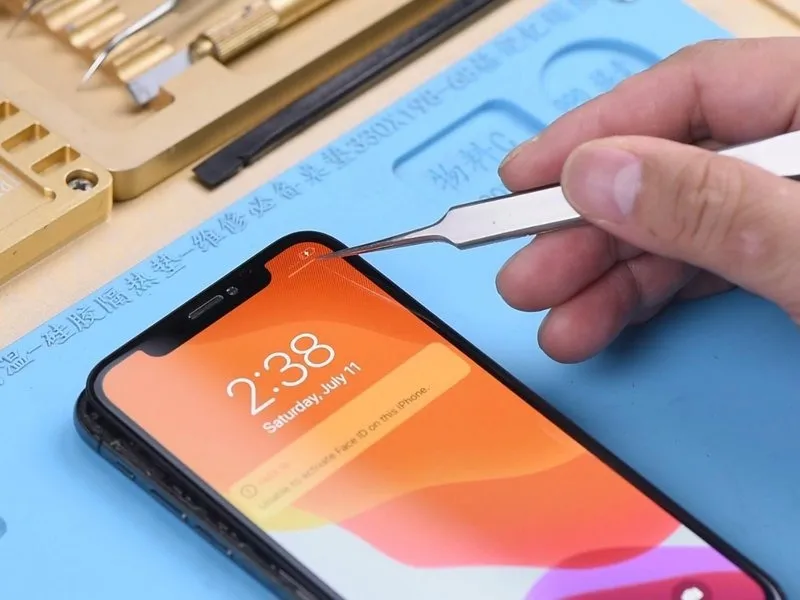
Thoroughly verify the integrity of the bond between the two layers to confirm a flawless soldering connection. - With the motherboard secured and the display assembly attached, proceed with phone reassembly and functional testing.
Connect the charging cable; a lightning bolt indicator should appear on the display, and the ammeter should register a standard charging current, indicating successful fault resolution.