iPhone XR LCD and Digitizer Replacement
Because some replacement displays incorporate a pre-attached thin metal protective layer, this condensed procedure is applicable for those situations.This metallic layer is referred to as an LCD shield plate.Should your replacement display lack this LCD shield plate, proceed with the detailed instructions below to perform the screen replacement.This comprehensive guide details the process of screen replacement while retaining the original LCD shield plate.The earpiece speaker and sensor assembly, which is uniquely bonded to your iPhone during manufacturing, requires transfer from the old display to the new one.This assembly incorporates the flood illuminator, a critical element of the Face ID biometric security system.Damage or substitution of this assembly will render the Face ID feature inoperable.
Exercise extreme caution to prevent any damage to these sensitive components throughout the repair process.Restoration of Face ID functionality after component damage or replacement is exclusively possible through Apple’s services.Be aware that True Tone display calibration will be deactivated following a screen replacement.This deactivation persists even when utilizing a genuine Apple replacement screen.The pre-installed metal LCD shield plate simplifies the repair process for certain replacement displays.A detailed procedure is necessary when the LCD shield plate is absent from the replacement display.Careful handling of the earpiece speaker and sensor assembly is essential to maintain Face ID functionality.
True Tone display functionality is temporarily suspended after screen replacement, regardless of the screen's origin.
Step 1 | Remove the pentalobe screws
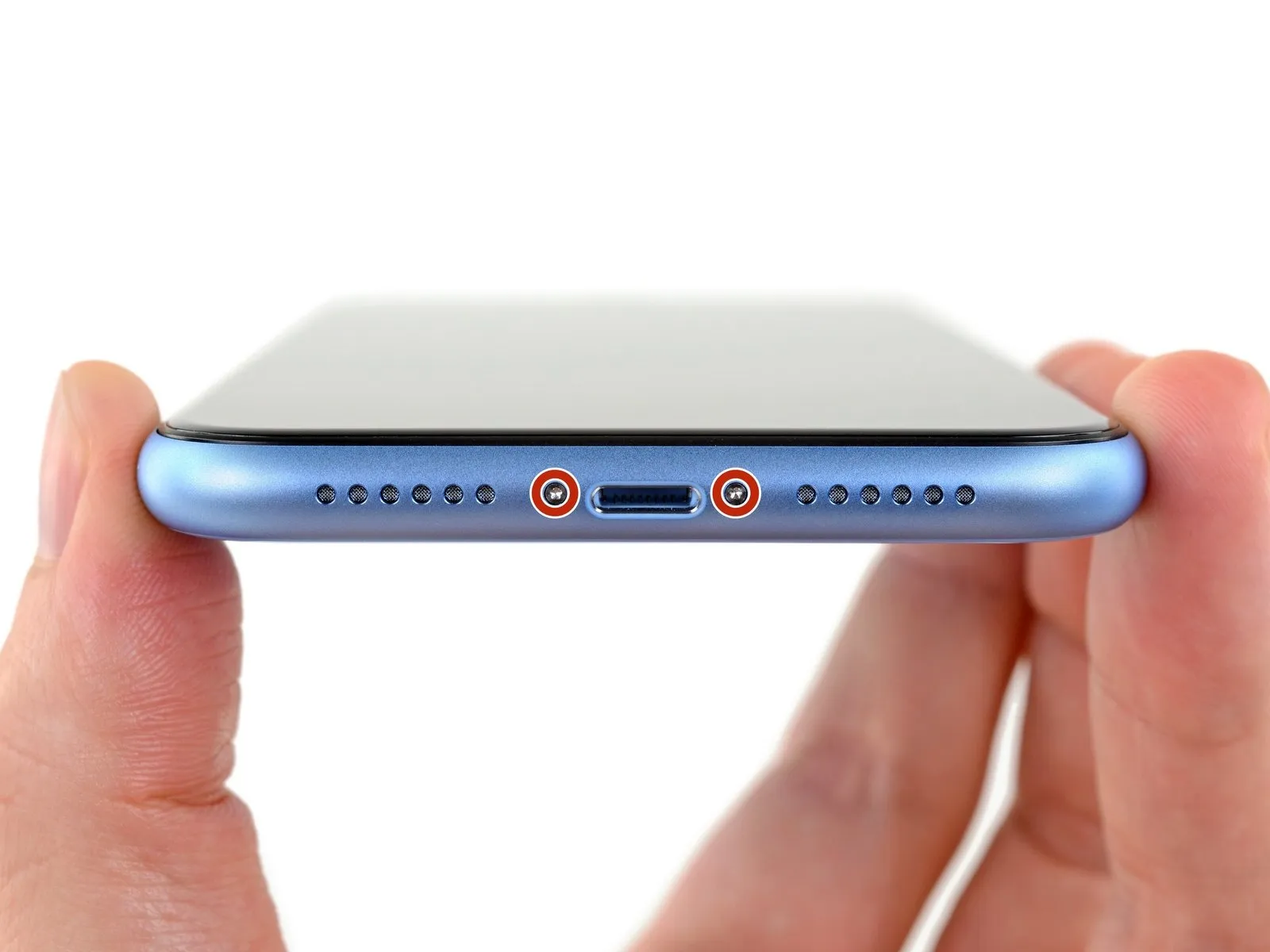
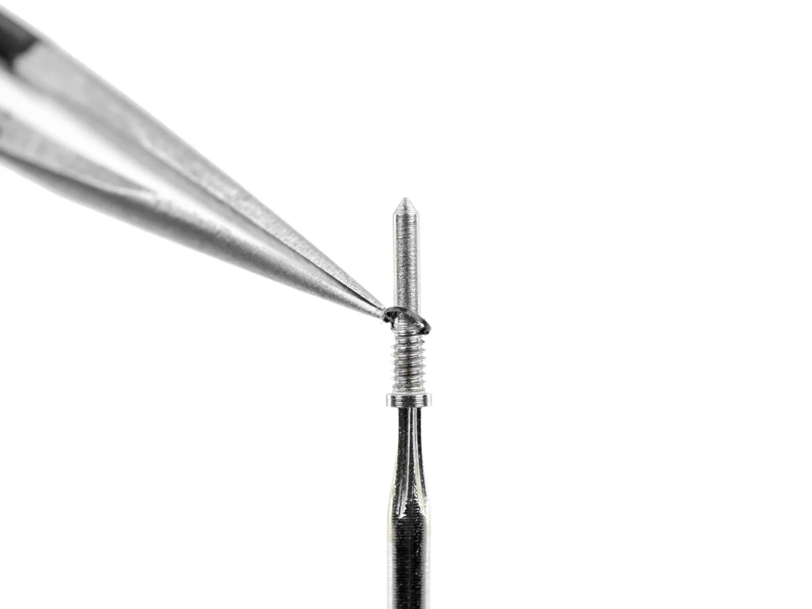
- To initiate the repair process, ensure the iPhone's battery level is reduced to less than 25% capacity.A fully charged lithium-ion battery presents a fire hazard and potential explosion risk if it sustains physical damage.To prevent electrical shock and potential component damage, completely deactivate the iPhone prior to any disassembly procedures.
- Carefully unscrew and remove the two pentalobe fasteners, each measuring 6.7 mm in length, located along the iPhone's lower edge.
- Disassembly of the iPhone will inevitably damage the factory-installed waterproof barriers; therefore, acquire replacement seals beforehand or exercise extreme caution to prevent liquid ingress during reassembly.
- Each pentalobe screw incorporates a small, black rubber gasket situated directly below the screw head; inspect these gaskets for wear or damage and consider replacing the screws to maintain optimal dust and moisture resistance.
- The integrity of these gaskets is crucial for preserving the iPhone's ability to resist dust and liquid intrusion, and their condition should be assessed or replacement performed during reassembly.
Step 2 | Mark your opening picks


- Excessive insertion of a prying tool risks device harm; this procedure establishes a reference point to avoid such damage.
- Using a precise measuring tool, determine a distance of3 millimetersfrom the tool's distal end and clearly indicate this measurement on the prying tool with a permanent marking instrument.
- For enhanced precision, consider applying distinct markings representing various distances to the tool's other corners.
- As an alternative method for limiting insertion depth, affix a coin to the prying tool's tip, positioning it3 millimetersaway from the point.
Step 3 | Tape over any cracks


- To mitigate additional damage and potential injury while repairing a screen with cracks on your iPhone, secure the fractured glass with adhesive tape.
- Apply layers of packing tape across the iPhone's display surface, ensuring complete coverage of the entire face.
- This method serves to retain loose glass fragments and maintain structural stability during the display separation process.
- Always utilize eye protection to guard against glass debris that may become dislodged during the repair procedure.
- Should difficulties arise in adhering a suction cup due to the broken glass, consider employing a folded, durable tape (like duct tape) as a handle to lift the display.
Step 4 | Tape over any cracks
- To mitigate additional damage and potential injury when addressing a cracked iPhone display, secure the fractured glass with adhesive tape.
- Apply successive layers oftransparent packing tapeacross the iPhone's display surface, ensuring complete coverage of the entire front panel.
- Protect your vision by utilizing safety glasses, as shards of glass may become dislodged during the repair process.
- Should the suction cup fail to maintain adhesion in subsequent procedures, construct a handle from a robust tape (like duct tape) and employ it to elevate the screen.
- As a last resort, secure the suction cup to the display with superglue if other methods prove ineffective.
Step 5 | Anti-Clamp instructions


- The subsequent three actions illustrate the utilization of the "Anti-Clamp" device, a custom-built tool intended to simplify the initial separation process.Should you choose not to employ the "Anti-Clamp", proceed directly to the instructions three steps further down.Detailed guidance regarding the operation of the "Anti-Clamp" is available in a separate, dedicated resource.
- To release the locking mechanism, draw the blue handle in a rearward direction.The device's gripping arms are then disengaged.Carefully position the arms across either the left or right side of the iPhone's frame.
- Ensure the suction cups are situated close to the iPhone's lower boundary, with one cup on the front face and the other on the rear.Apply pressure by compressing the cups together to generate a vacuum seal on the intended surfaces.In instances where the iPhone's exterior exhibits excessive slipperiness, preventing adequate adhesion by the "Anti-Clamp", adhesive tape can be employed.
- The tape will provide a more textured surface, enabling a stronger grip.
- This enhancement allows the "Anti-Clamp" to maintain a secure hold during the disassembly.
- The "Anti-Clamp"'s design facilitates easier access to internal components.
- The specialized tool minimizes the risk of damage during the opening procedure.Refer to the supplementary guide for a comprehensive explanation of the "Anti-Clamp"'s functionality.Proper use of the "Anti-Clamp" contributes to a safer and more efficient repair process.
Step 6


- Advance the blue handle to secure the arm assemblies in their engaged position.
- Rotate the handle a full 360-degree circle, or continue until the suction cups exhibit signs of deformation.
- Maintain parallel positioning of the suction cups; should misalignment occur, slightly reduce the suction cup's grip and reposition the arm components.
Step 7


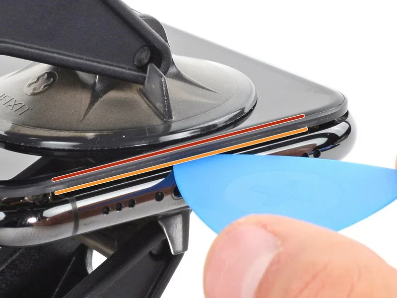
- Employing an iOpener, introduce it between the Anti-Clamp’s arms by threading it through.Alternatively, utilize a hairdryer, heat gun, or hot plate for warming, but exercise caution as excessive temperatures may compromise the display or internal battery.Position the iOpener to rest along the lower edge of the iPhone’s frame, ensuring it is folded appropriately.Allow a sixty-second interval to permit the adhesive to loosen and form a separation.Carefully slide an opening pick beneath the screen and the surrounding plastic bezel, avoiding direct contact with the display surface.
- Should the Anti-Clamp fail to generate a satisfactory separation, increase the heat applied and rotate the handle incrementally by ninety degrees.Avoid exceeding a ninety-degree rotation at any point, and observe a sixty-second pause between adjustments.Rely on the Anti-Clamp’s pressure and the passage of time to facilitate the separation process.
- The iOpener serves as a tool to assist in separating the device's components.
- Heat application should be controlled to prevent damage to sensitive components.
- A one-minute waiting period is crucial for adhesive release.The opening pick must be inserted with precision to avoid screen damage.Incremental rotations of the Anti-Clamp handle are recommended for optimal results.
- Allowing sufficient time between handle rotations is essential for successful separation.The Anti-Clamp’s design facilitates a controlled separation force.The plastic bezel is the intended target for the opening pick’s insertion.
Step 8 | Heat up the screen
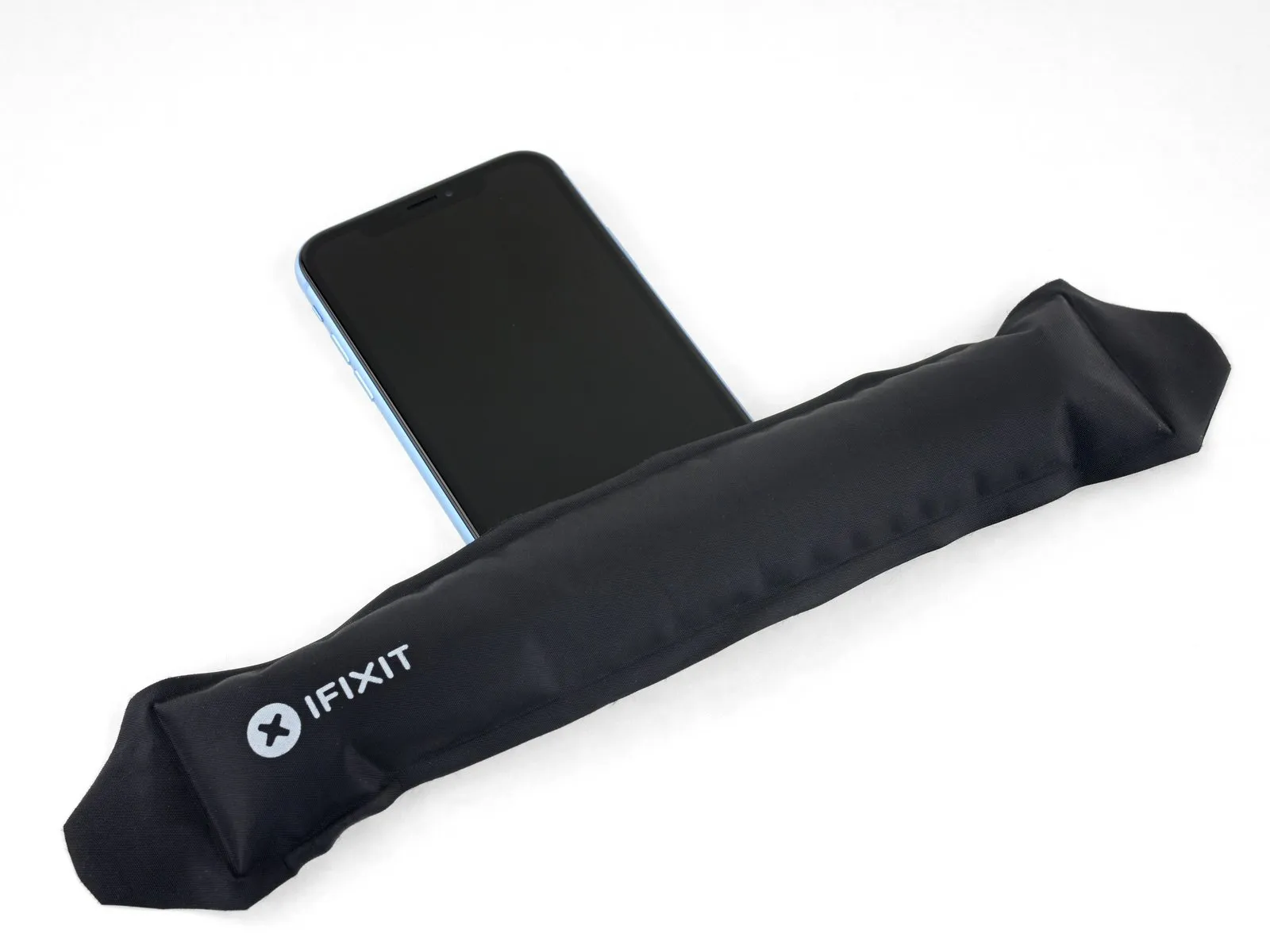
Applying warmth to the iPhone's bottom perimeter facilitates the loosening of the adhesive that holds the display in place, thereby easing the separation process.A hairdryer or heat gun can be employed for this purpose, or alternatively, an iOpener can be applied to the lower edge for roughly sixty seconds to reduce adhesive bond strength.The purpose of this heating step is to render the adhesive more pliable, simplifying the display removal procedure.
Step 9
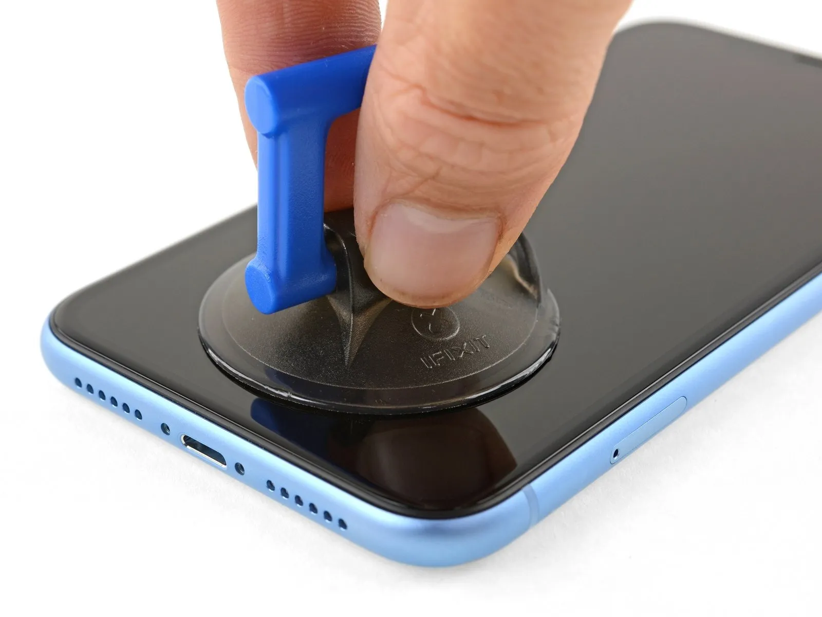
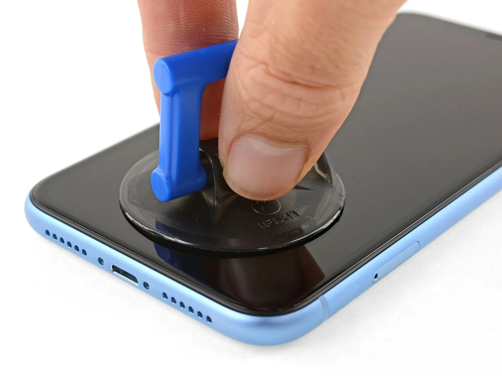
When employing a solitary suction handle, position it against the lower boundary of the device, ensuring the curved glass surface remains untouched.
Step 10 | Lift the display slightly
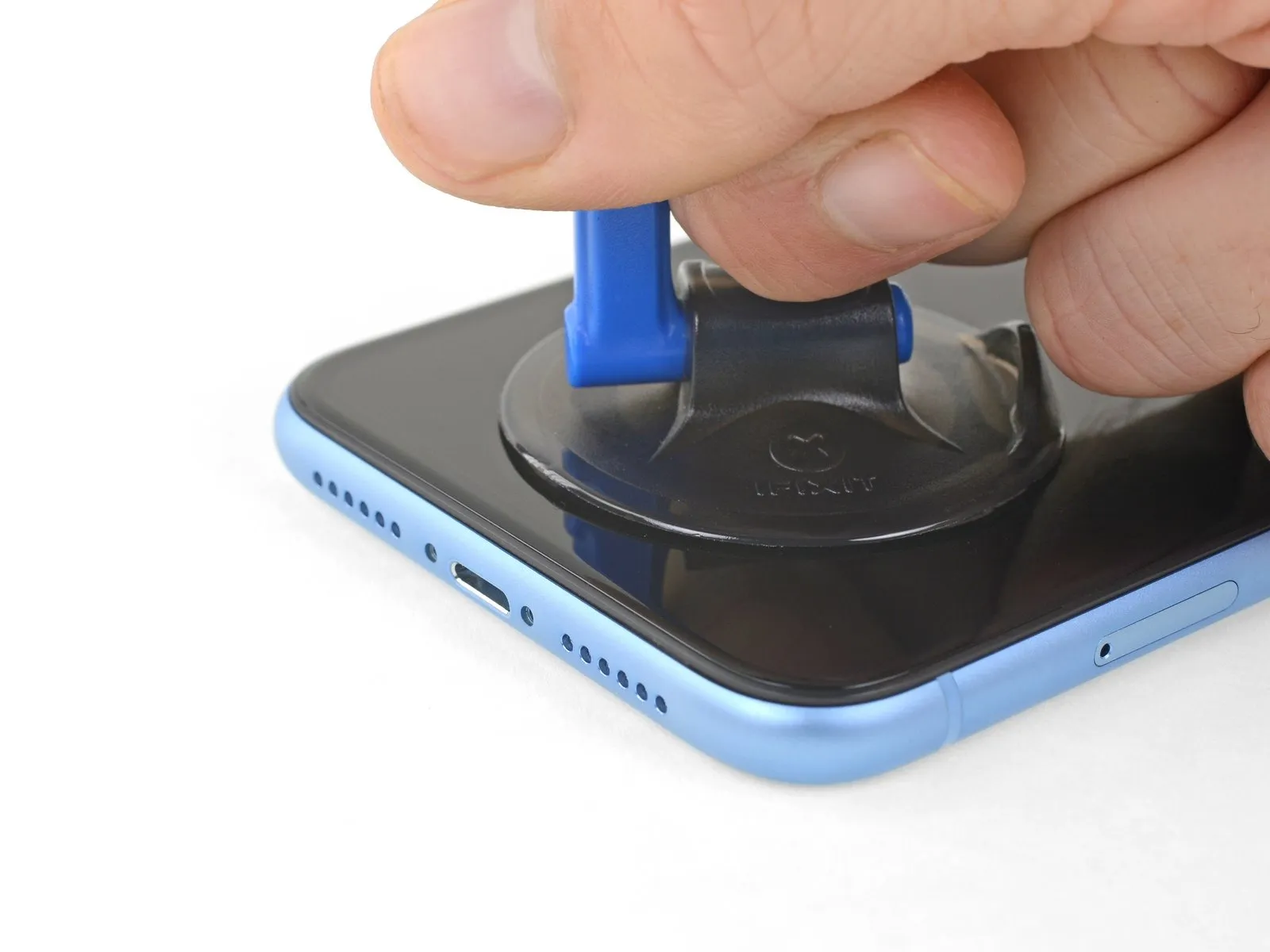
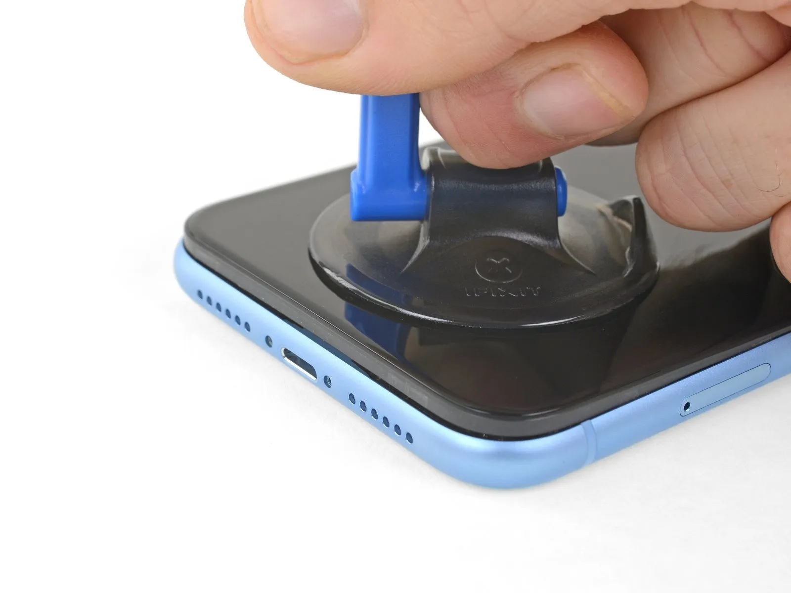
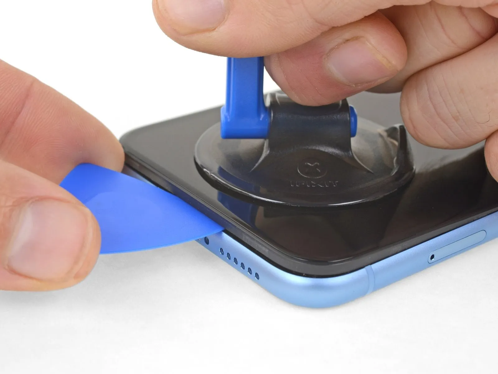
- Maintain consistent, forceful upward traction on the suction cup to establish a minimal separation between the device's front panel and its rear casing.
- Carefully slide an opening tool beneath the display and the surrounding plastic trim, ensuring it does not contact the screen's surface.
- Due to the robust nature of the waterproof sealant securing the display, a considerable amount of force might be necessary to initially create this separation; if encountering difficulty, apply additional heat and gently oscillate the screen to reduce adhesive strength until a sufficient gap is achieved for tool insertion.
Step 11 | Separate the screen adhesive
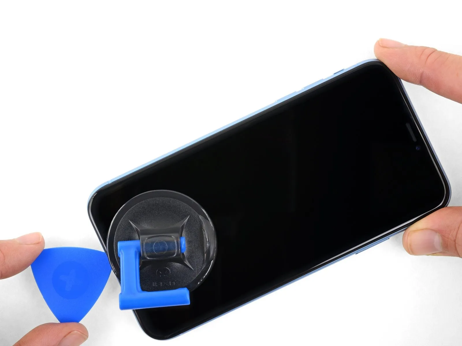
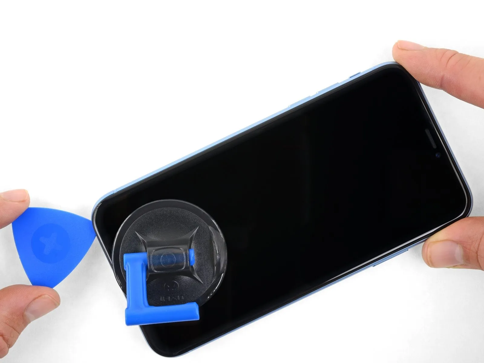
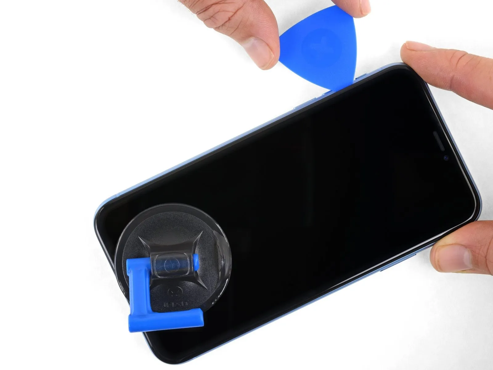
Employ the opening pick to maneuver along the lower-left perimeter of the iPhone's display, progressing upward along the left side, to sever the adhesive securing the display assembly.
Ensure the pick's insertion depth remains below 3 millimeters to prevent potential harm to delicate internal components.
Step 12 | Screen information
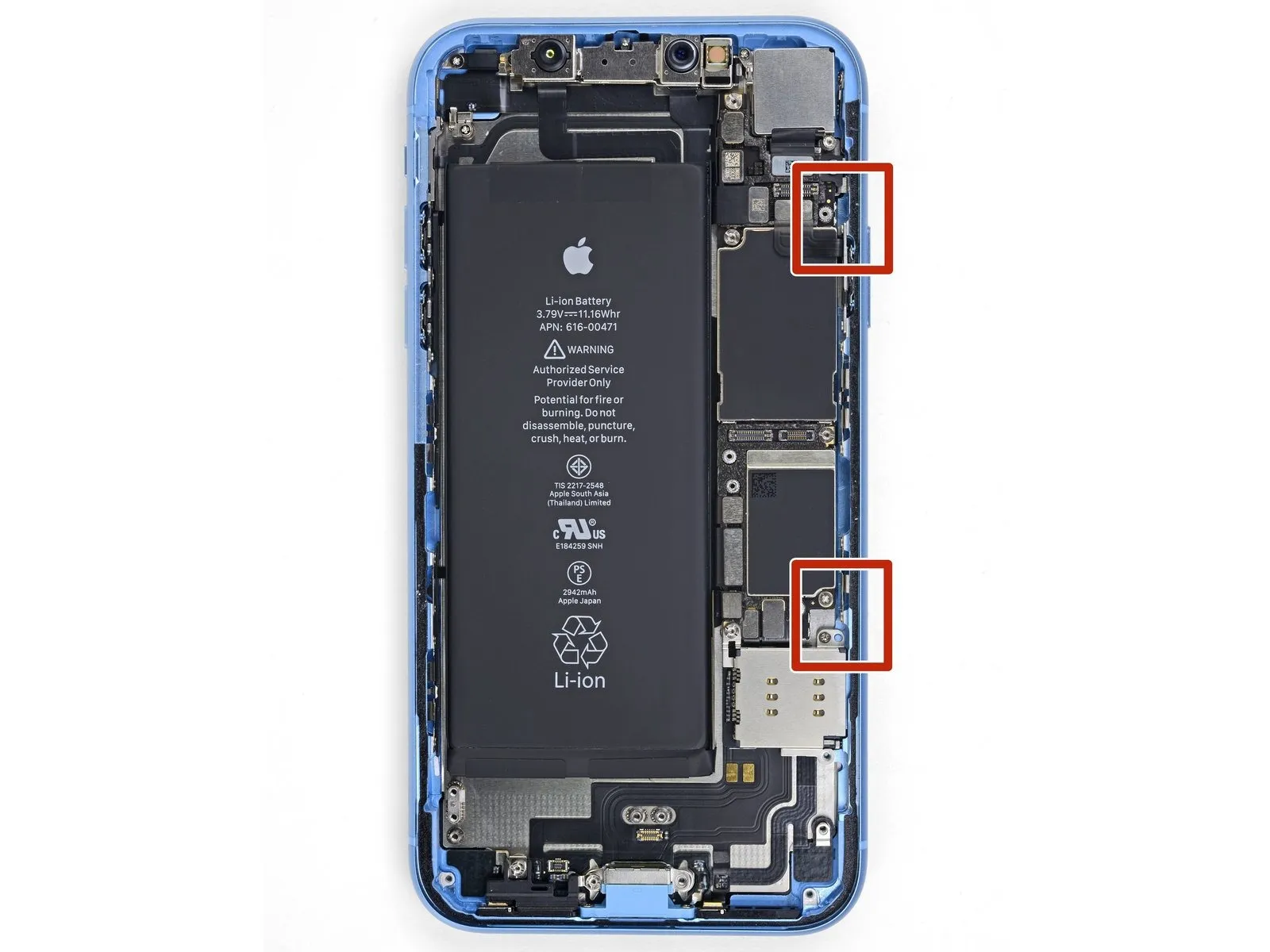
Fragile wiring is situated along the iPhone's right side; avoid inserting tools into the designated areas to prevent cable damage.
Step 13
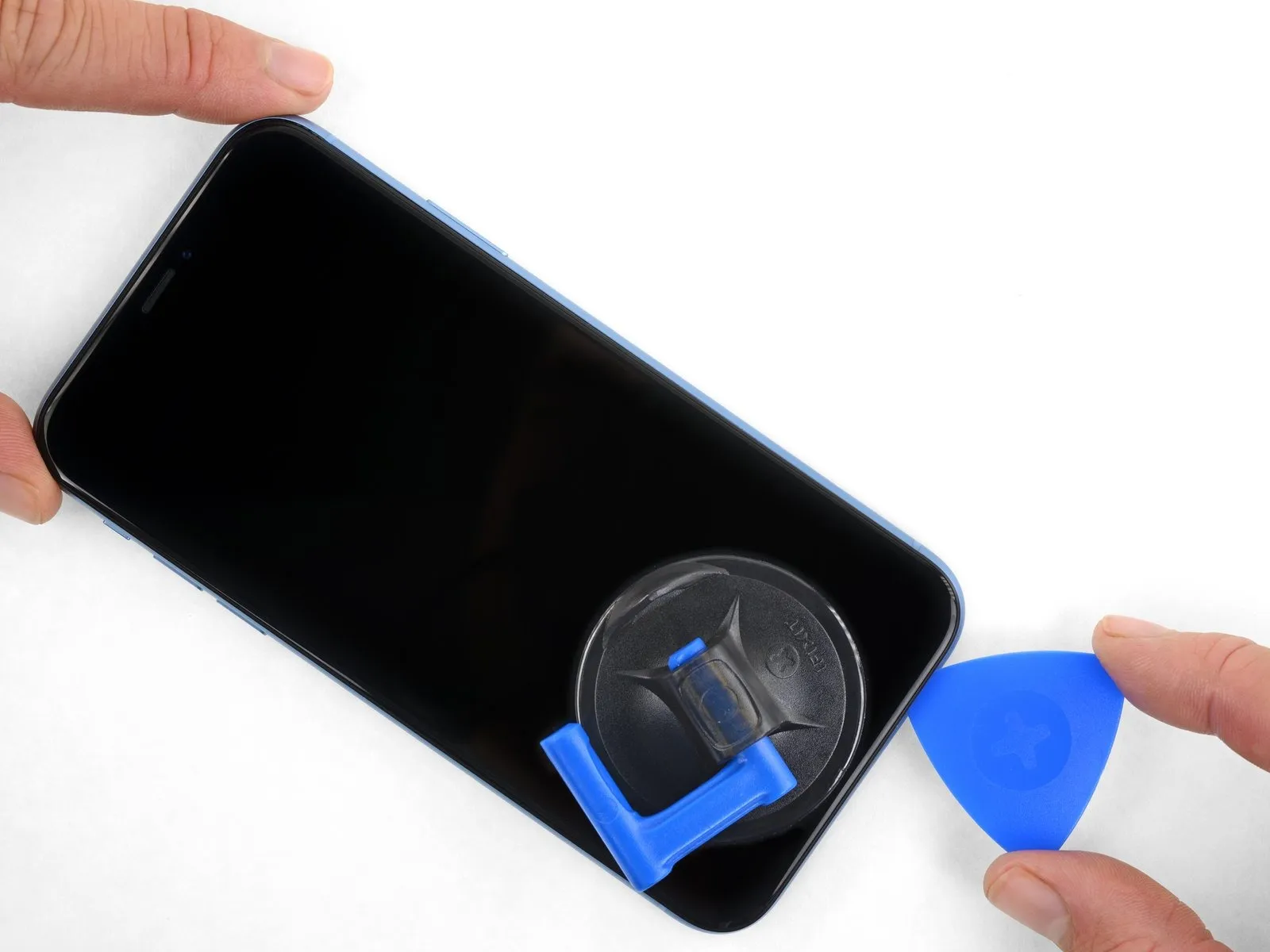
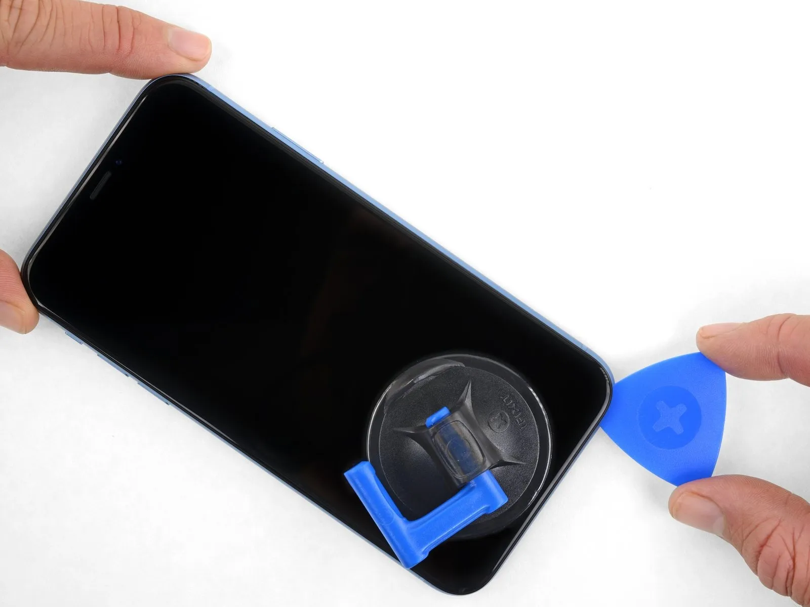
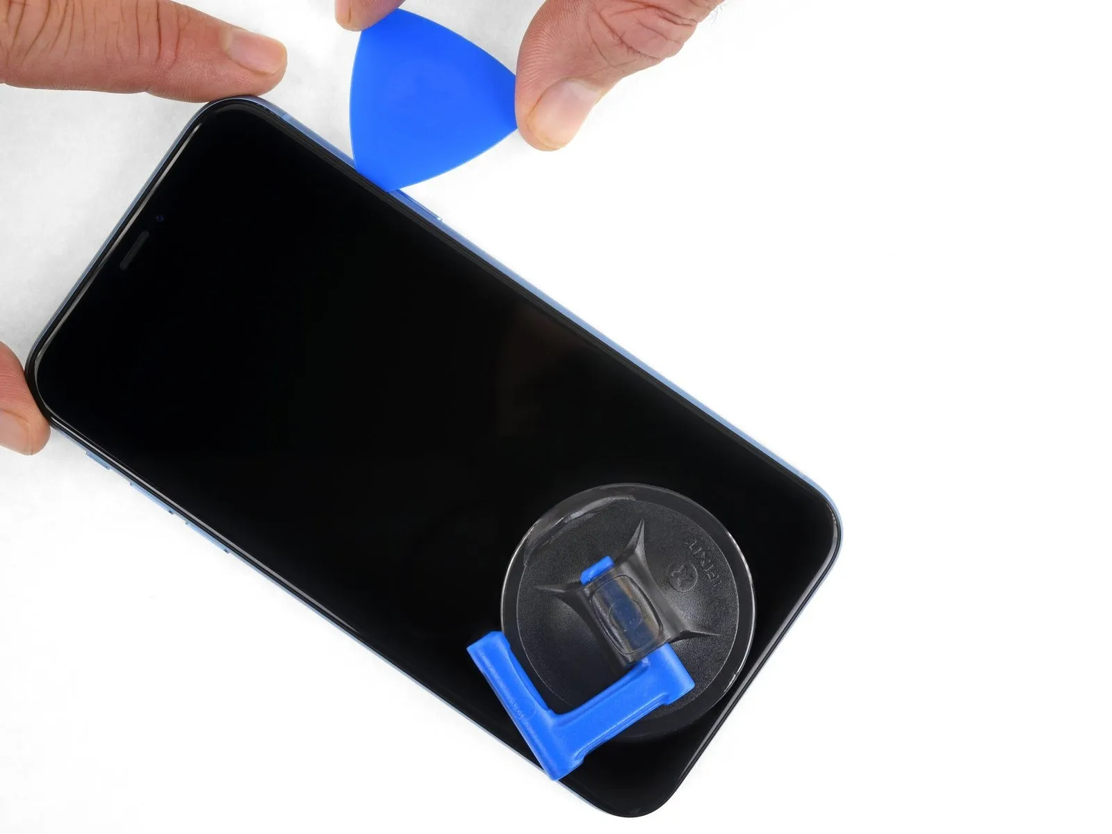
- Position a repair pick along the lower edge of the iPhone's casing.Advance the pick upwards along the right-hand side to further release the adhesive bond.
- Limit pick insertion depth to a maximum of 3 millimeters.Exceeding this depth poses a risk of damaging the delicate display cable connections.
Step 14
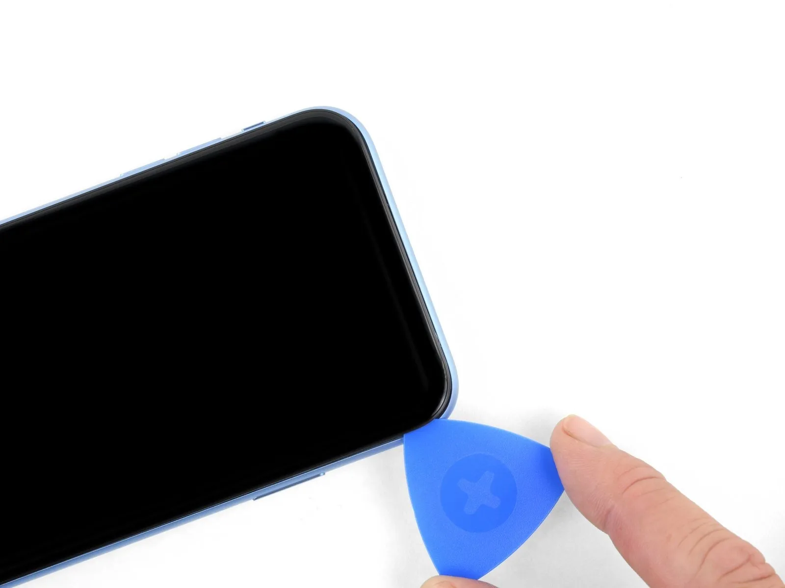
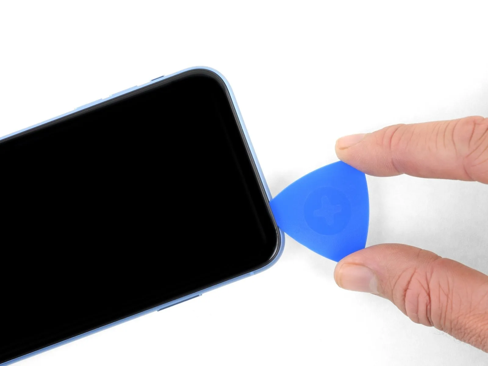
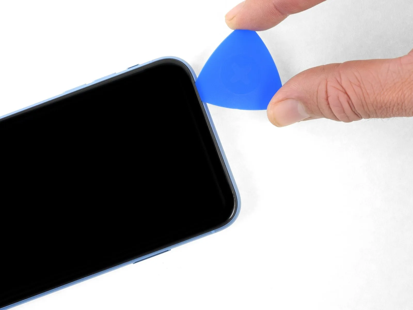
- Adhesive and retaining clips together fasten the display's upper boundary.Employing a separating tool, maneuver it along the display's upper corner while applying slight downward pressure towards the Lightning connector.
- Excessive force applied to the clips will result in their breakage; therefore, proceed with caution and deliberate movements.
- Limit the insertion depth of the separating tool to a maximum of 3 millimeters to prevent potential damage to the front panel sensor array.After releasing the initial corner, continue the separation process to the opposing corner, severing any residual adhesive holding the display in place.
- Complete the display detachment by sliding the separating tool across the remaining upper edge, releasing the remaining adhesive bonds.
Step 15
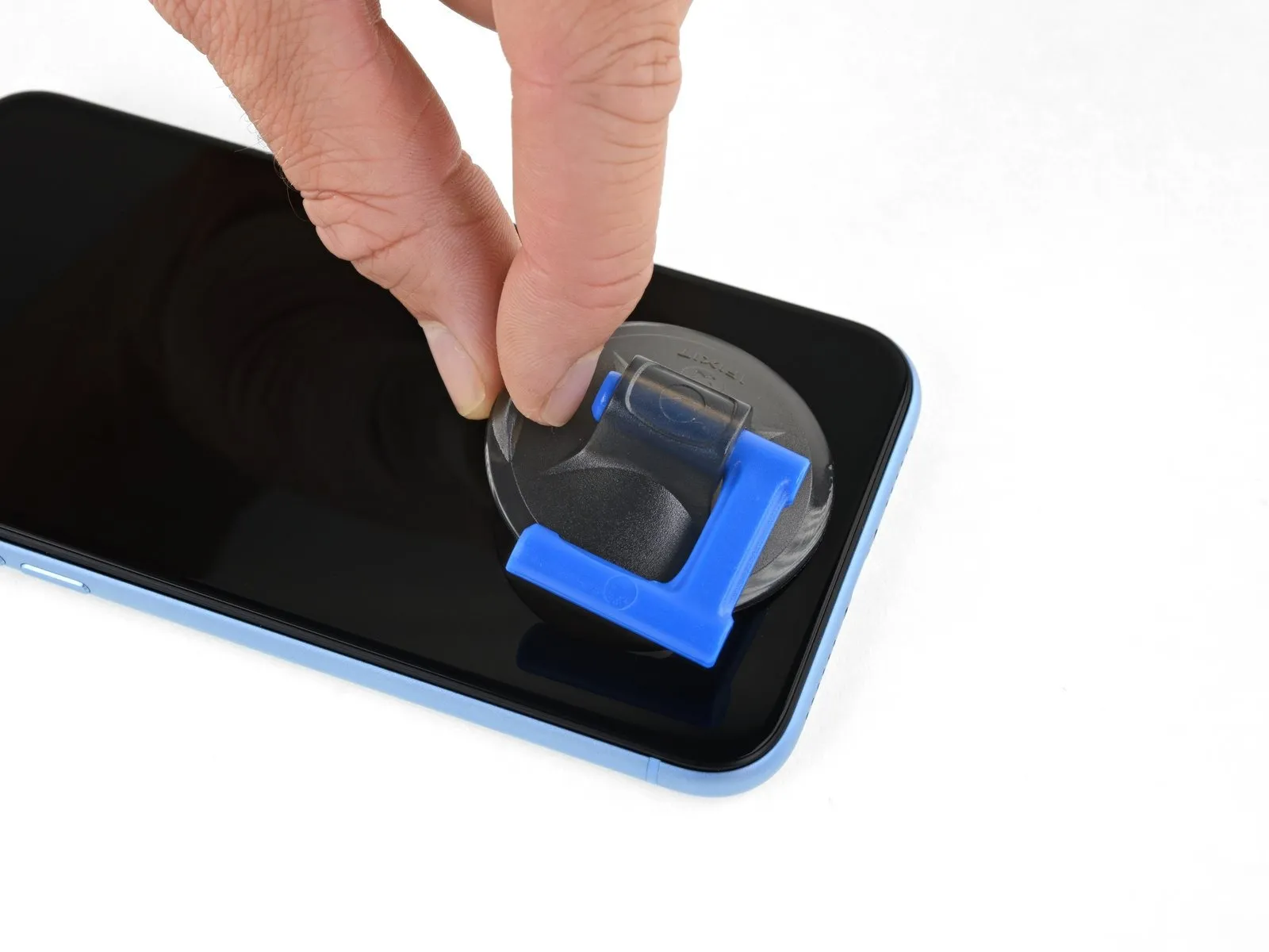
- To detach the suction cup from the front panel, grasp and exert force on the small protrusion located on its surface.
Step 16 | Open the iPhone
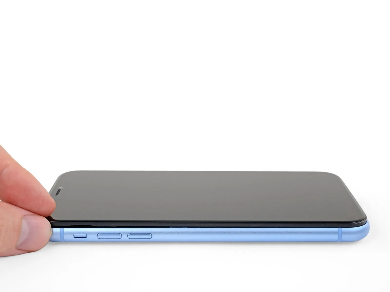
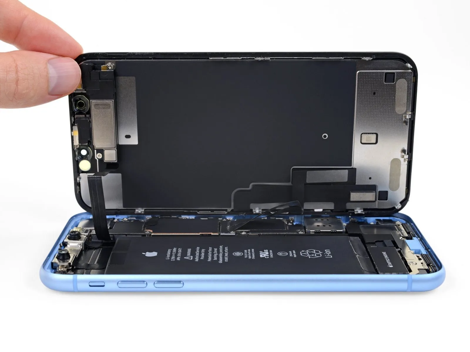
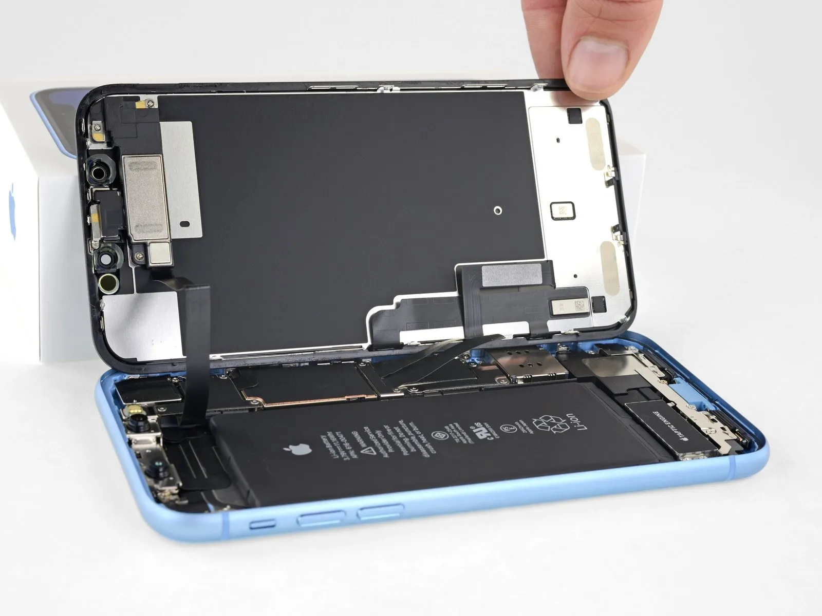
- Initiate the iPhone's disassembly process by pivoting the display assembly upwards, starting from the left edge, mimicking the action of opening a book's cover.
Refrain from completely disconnecting the display at this stage, because multiple delicate ribbon cables maintain its electrical connection to the iPhone's logic board.
To facilitate access to the internal components, secure the display in an open position using a support.
When reassembling the device, position the display, ensuring proper clip alignment along the upper edge, and apply controlled pressure to the top edge before securing the remainder of the display; if resistance is encountered, inspect the display's perimeter clips for any deformation.
Step 17 | Unscrew the battery connector cover
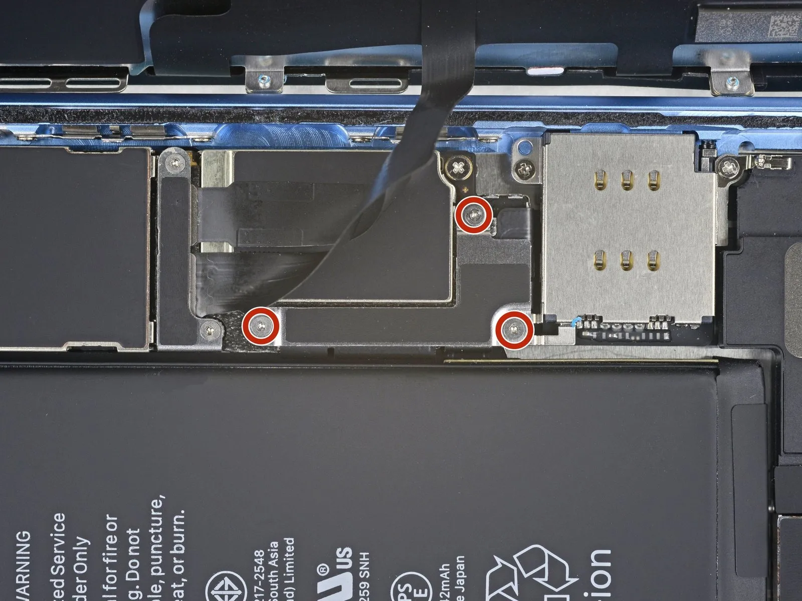
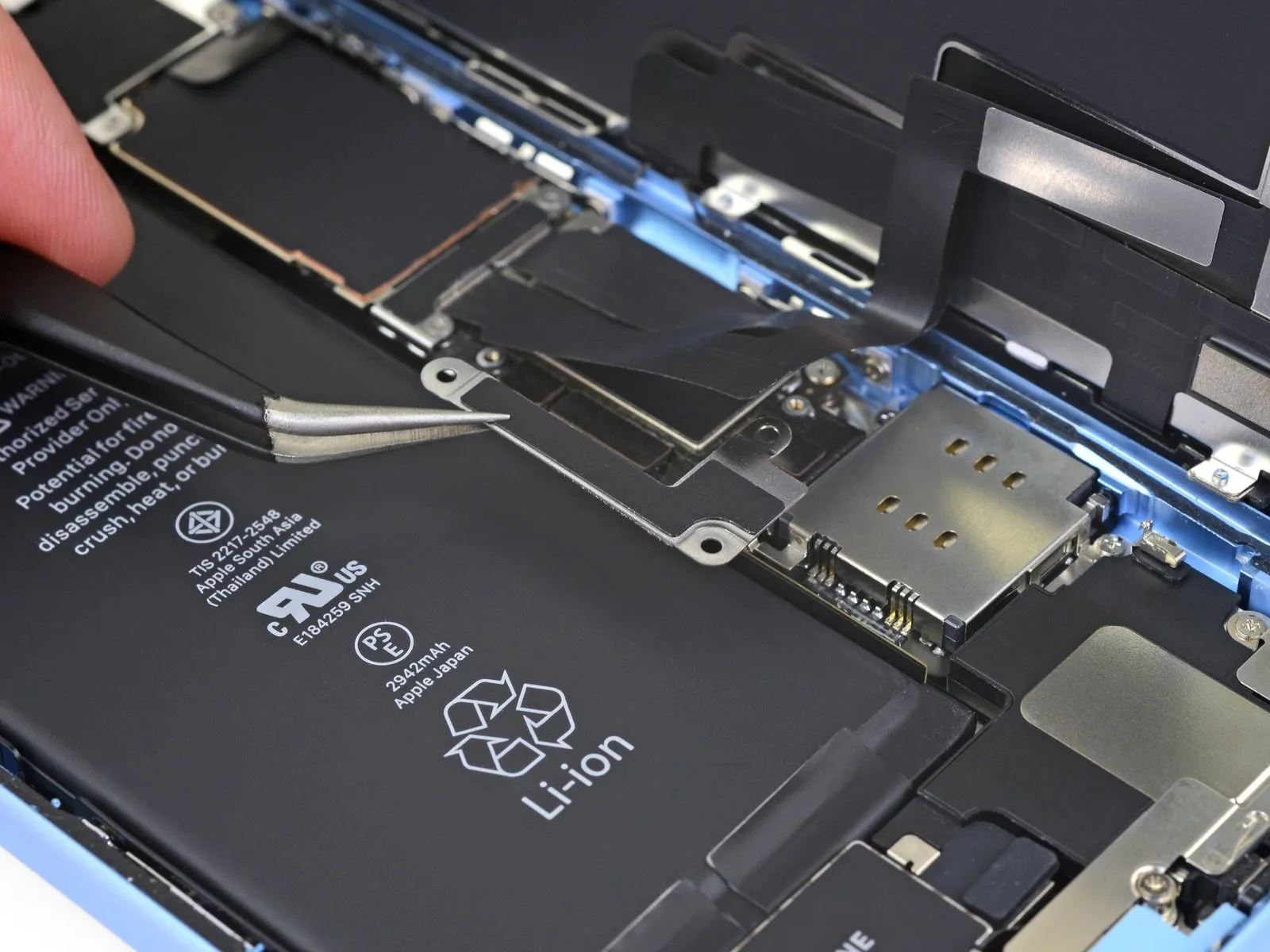
- Detach the battery connector cover bracket using three 1.2 mm Y000 screws.The bracket that secures the battery connector should now be removed.Carefully monitor the location of each screw throughout the repair process, ensuring correct placement during reassembly to prevent potential damage to the iPhone.
Prior to permanently reattaching the display, it's advisable to verify all iPhone functionalities by briefly powering it on at this stage.
Completely de-energize the iPhone by powering it off before proceeding with the remaining repair steps.
Proper screw management is crucial to prevent component damage and ensure correct reassembly of the iPhone.
Step 18 | Disconnect the battery
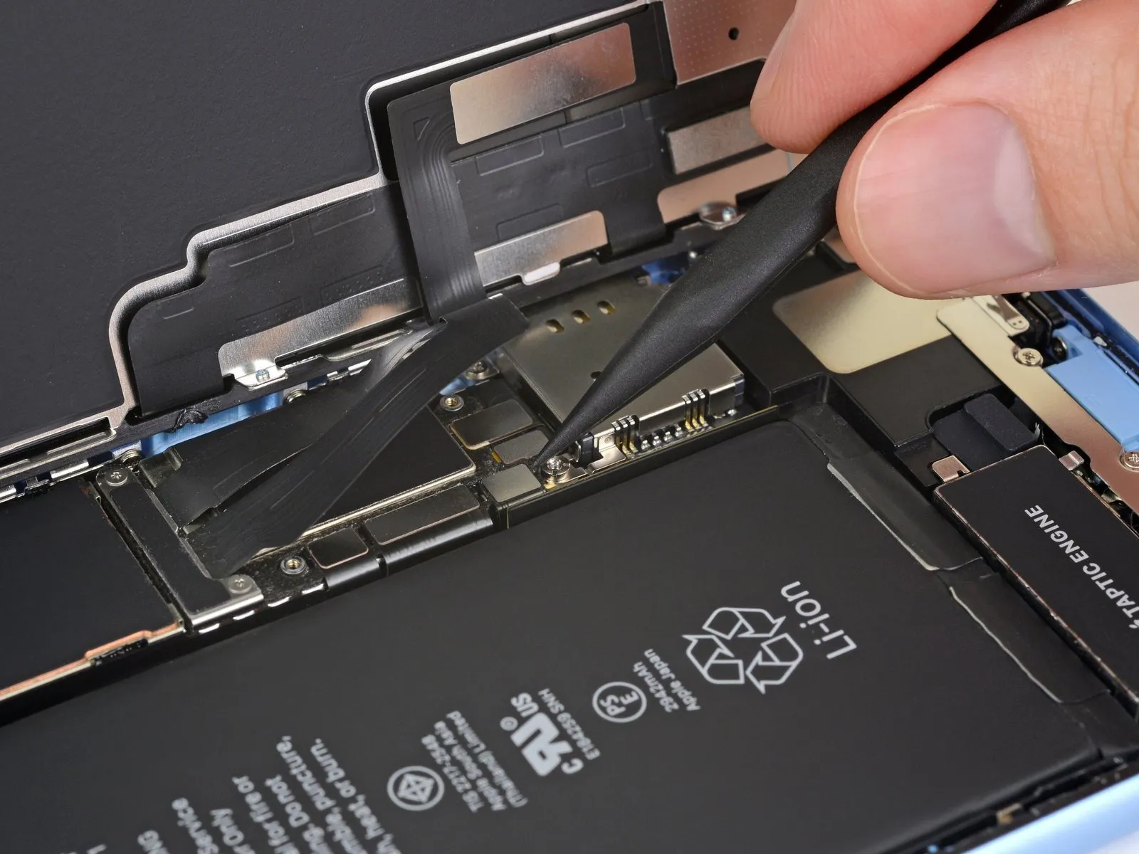
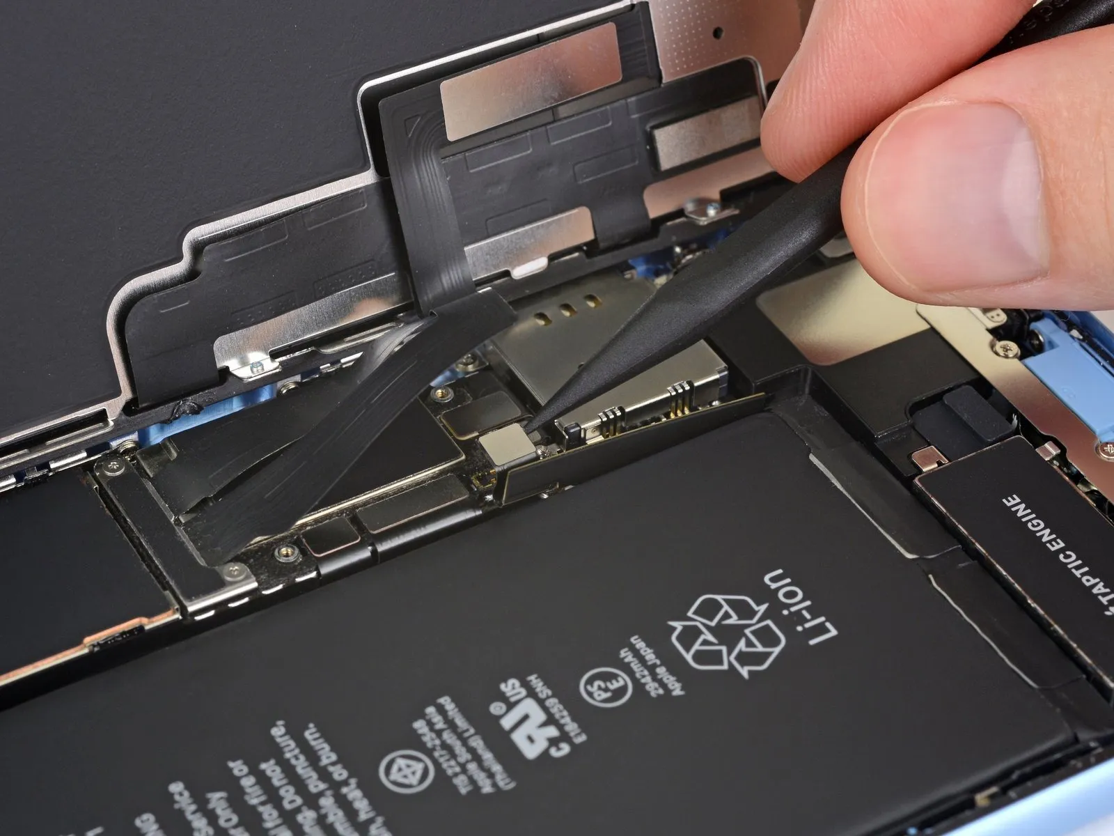
- Employ the tip of a spudger to lift the battery connector vertically from its corresponding receptacle.
Exercise caution to avoid harming the black silicone seals located around this connector and other board interfaces, as they offer supplemental defense against water and particulate contamination.
Slightly deflect the connector away from the main circuit board to ensure it cannot inadvertently establish an electrical connection with the socket and potentially energize the device during the repair process.
Step 19 | Unscrew the display connector cover
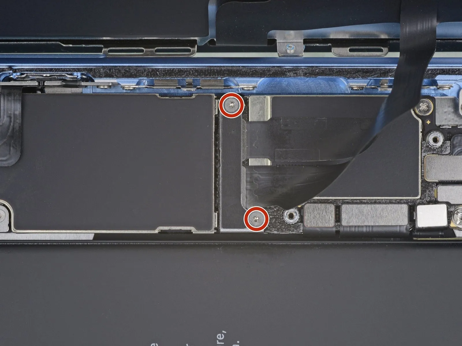
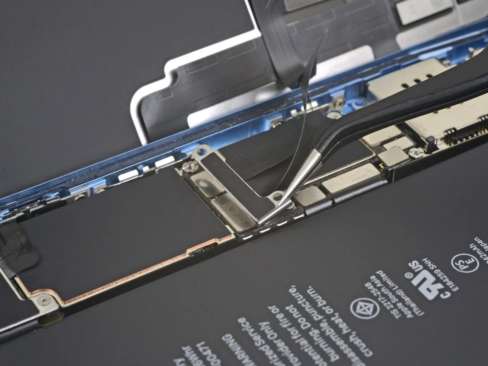
- Detach the display connector bracket by eliminating the two screws.The screws used for securing are sized at 1.2 millimeters and require a Y000 screwdriver for removal.The bracket's retention is achieved through these screws, necessitating their removal to proceed.
Following screw removal, the display connector bracket can be taken off.
Step 20 | Disconnect the digitizer
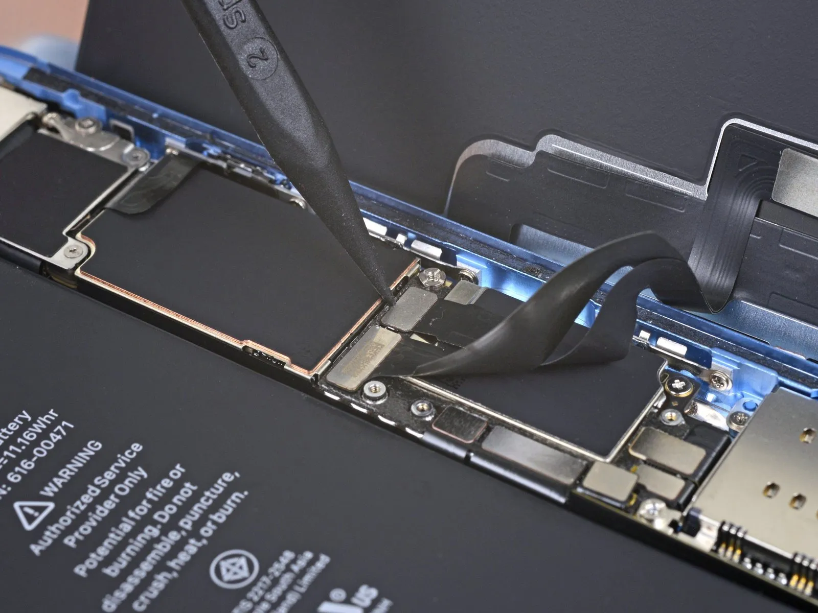
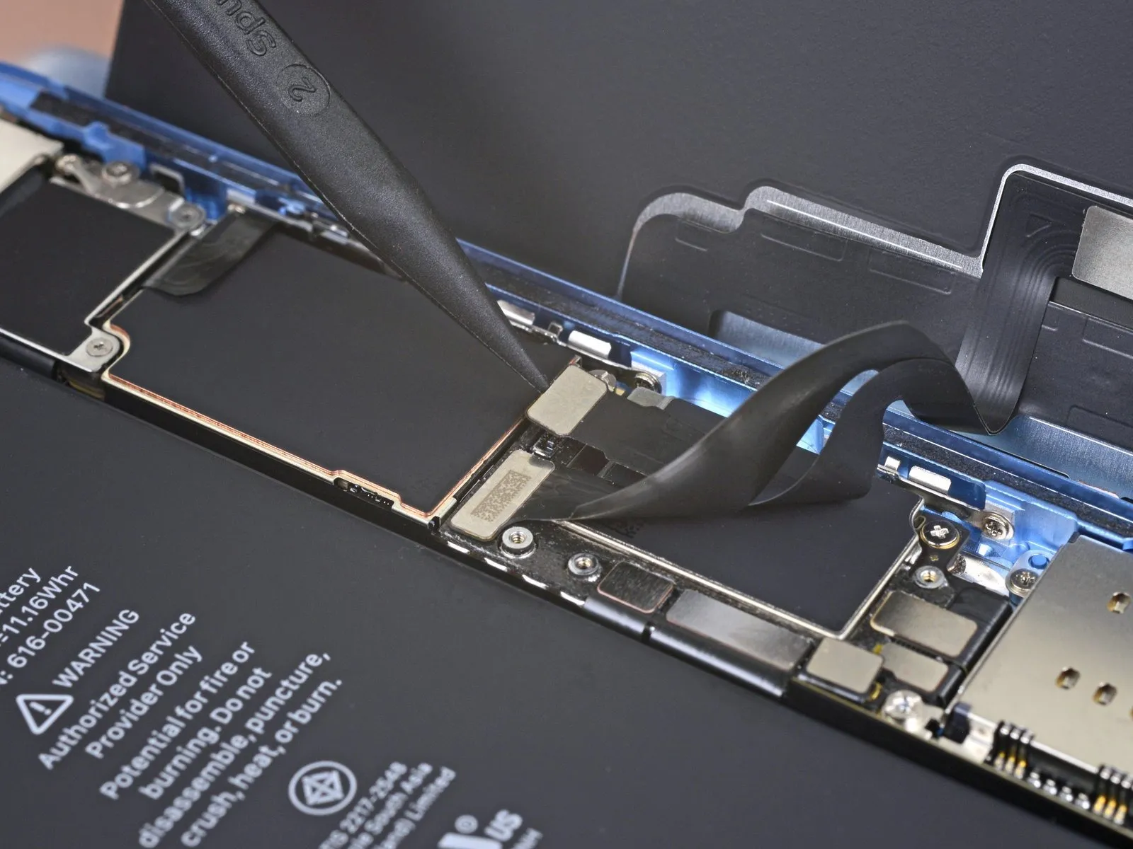
- Employ the pointed end of a spudger to gently lift and detach the digitizer cable.
For reattachment, apply pressure to the connector edges, ensuring precise alignment and a secure click on each side; avoid central pressure to prevent pin distortion and potential irreversible damage.
Should unresponsive areas appear on the display following the repair, first remove the battery, then re-secure this connector, verifying a complete click and inspecting the socket for dust or debris.
Step 21 | Disconnect the display
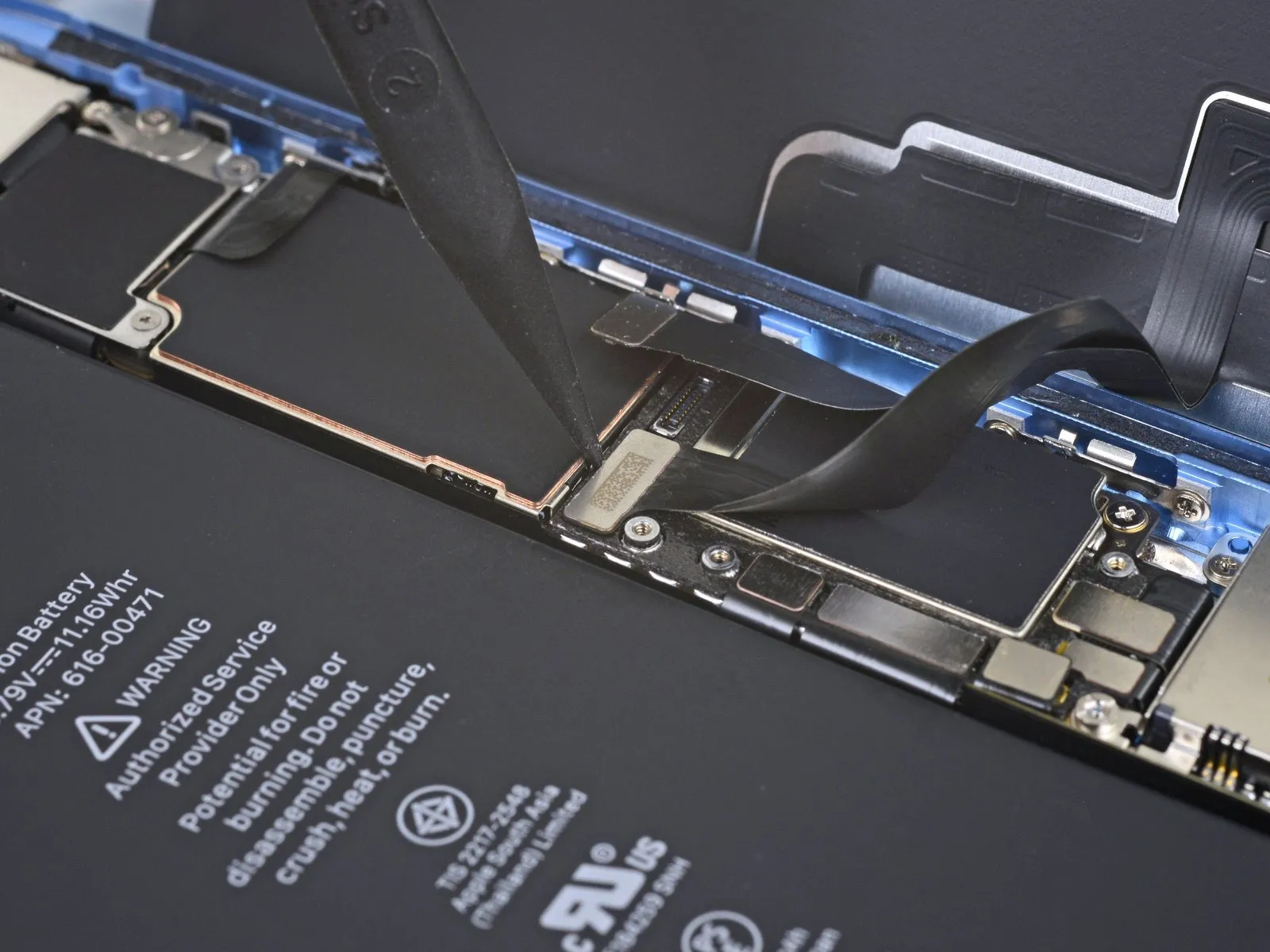
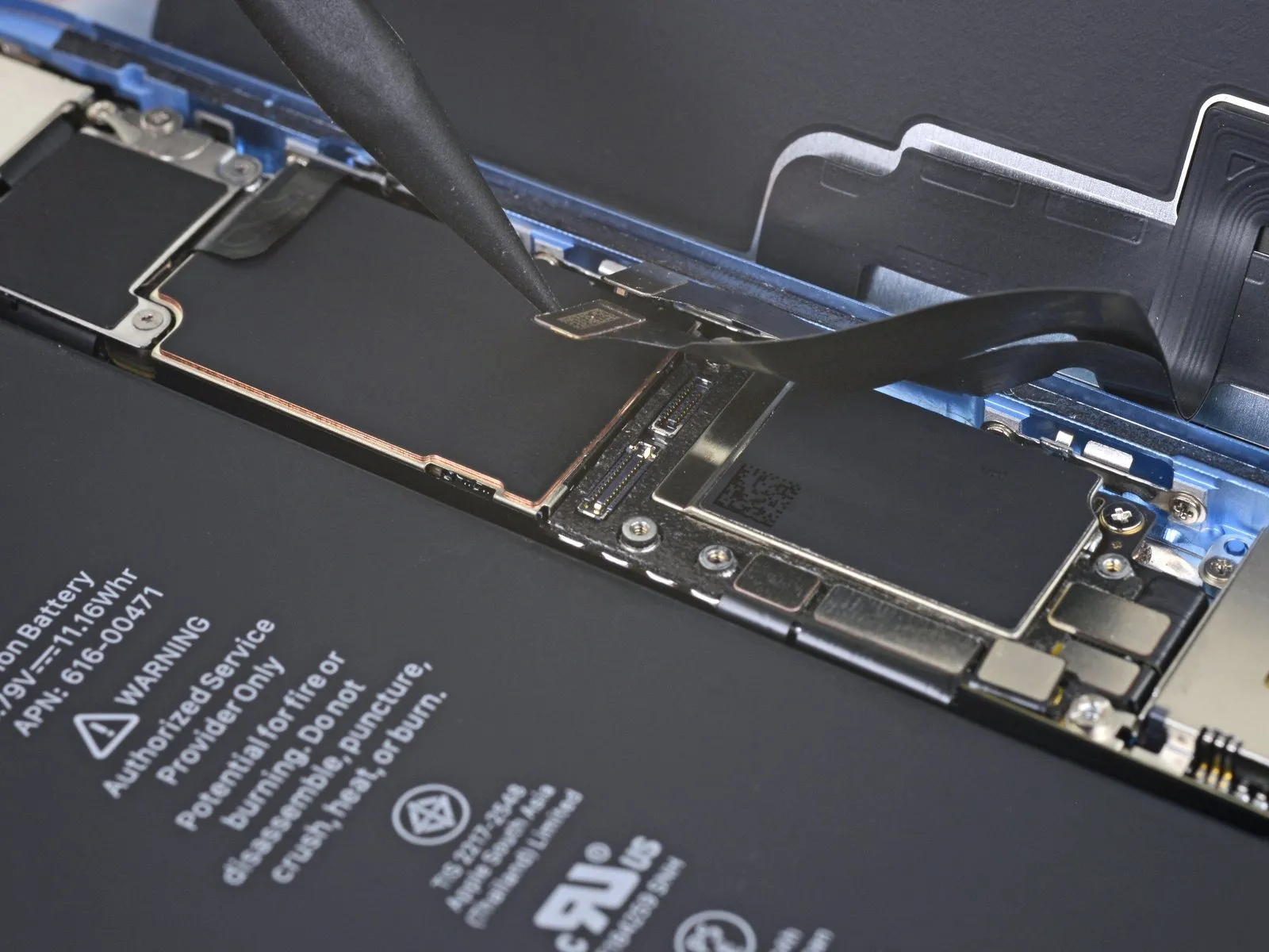
Step 22 | Unscrew the logic board connector cover
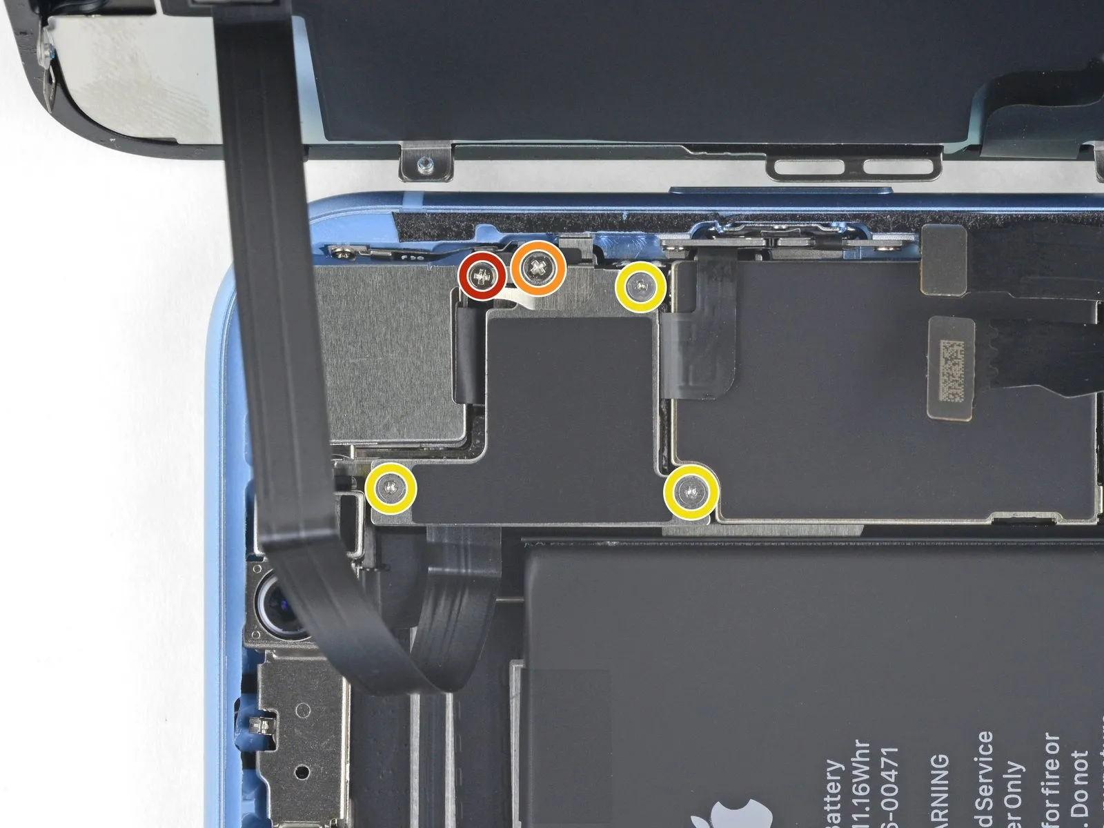
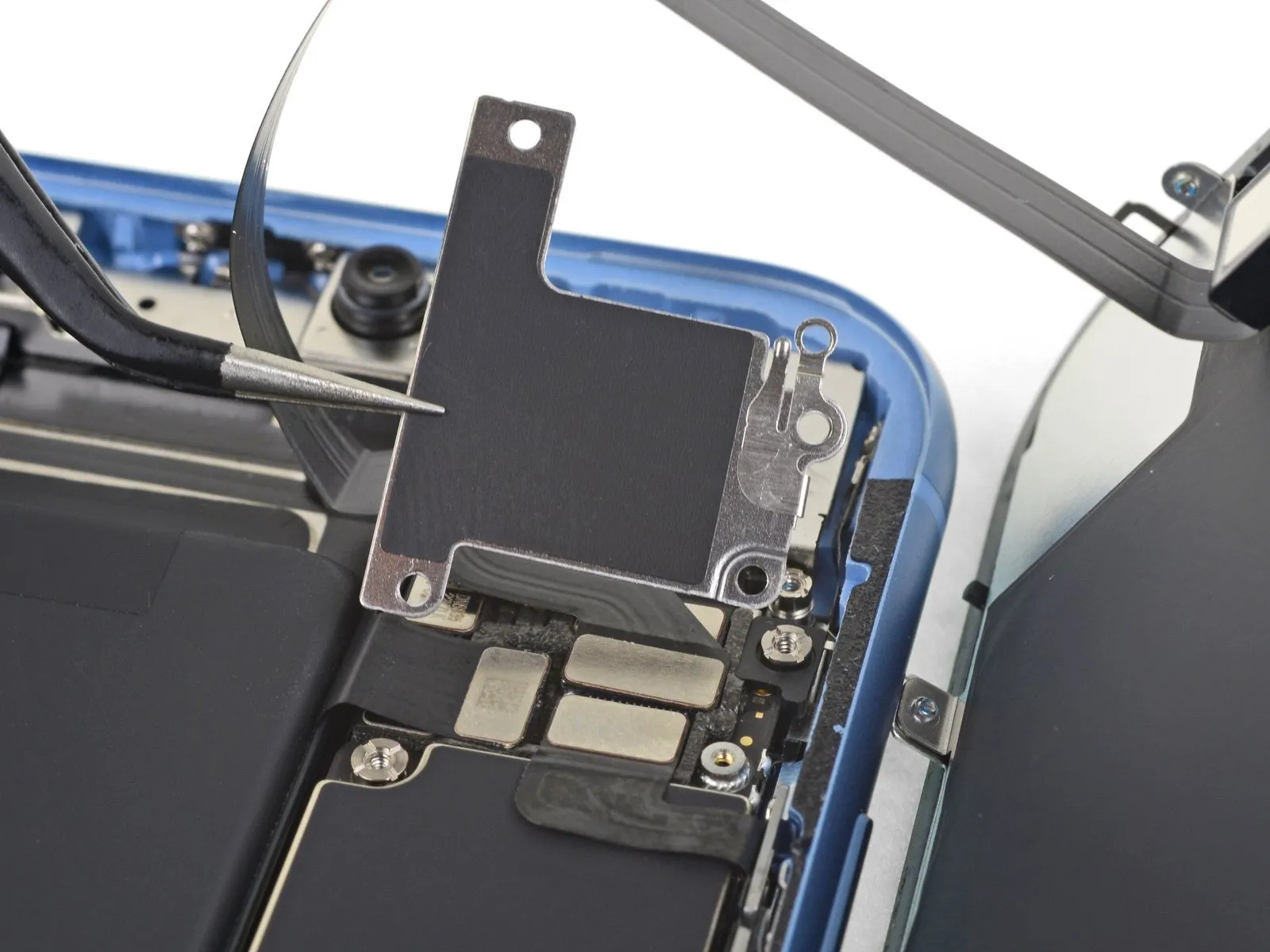
- To detach the logic board connector bracket from the rear case, it is necessary to eliminate the five screws that hold it in place.
- A single screw, measuring 1.3 mm in length, is required and should be a Phillips #000 type.A separate screw, with a 1.5 mm length, is also needed, and it must be a Phillips #000 type.
- Three screws, each measuring 1.2 mm, are also needed for this process and should be Y000 type screws.Proceed with the removal of the bracket after the screws have been eliminated.
- Exercise caution to prevent the loss of the smaller bracket attached to the edge of the larger bracket.This smaller bracket is affixed with a tiny clip, making it susceptible to accidental displacement.
- The smaller bracket's attachment is maintained by a small clip, increasing the risk of it being dislodged during the removal process.
- Careful handling is essential to avoid dislodging the smaller bracket, which is held in place by a delicate clip.
Step 23

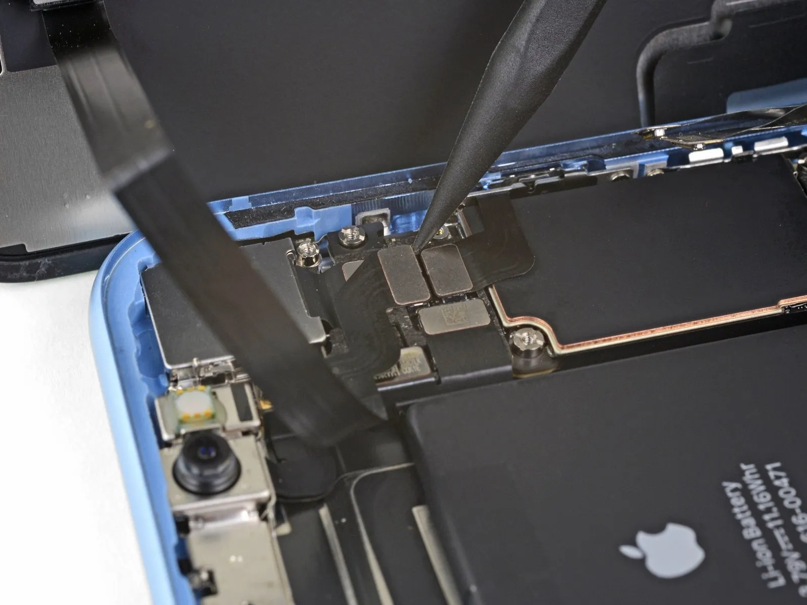
Step 24 | Disconnect the front sensors
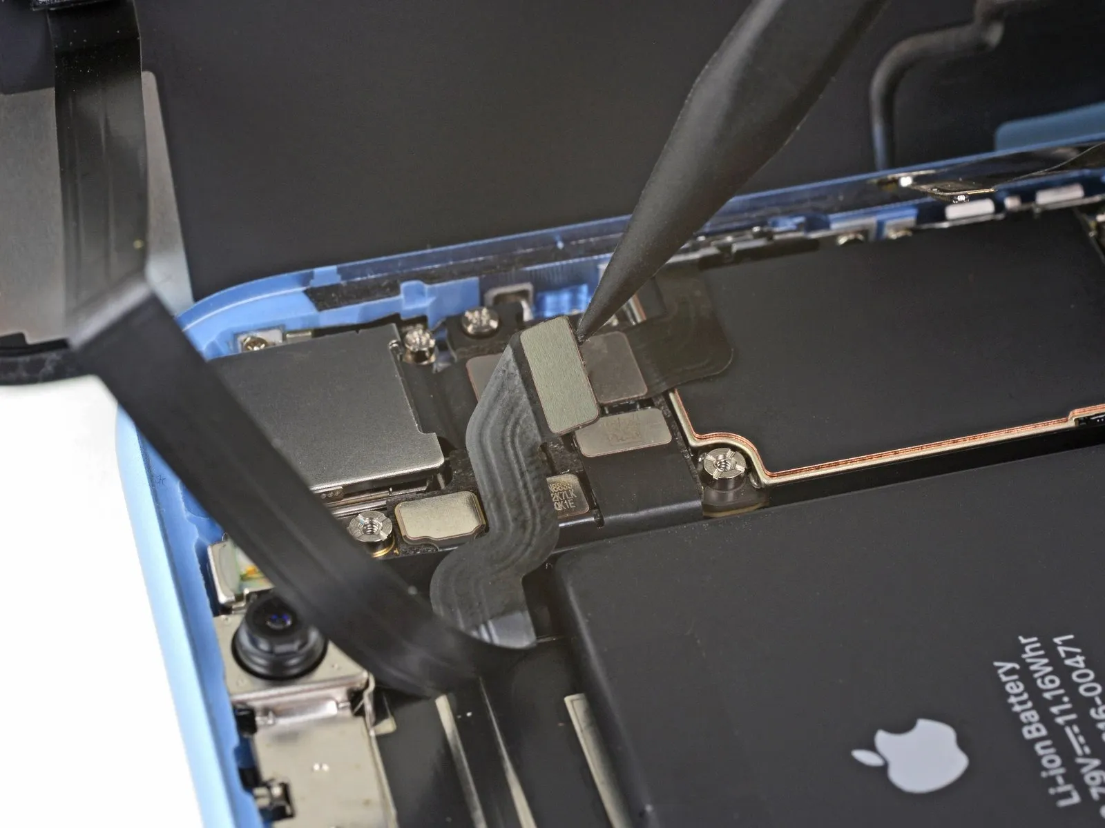
Step 25 | Remove the display assembly
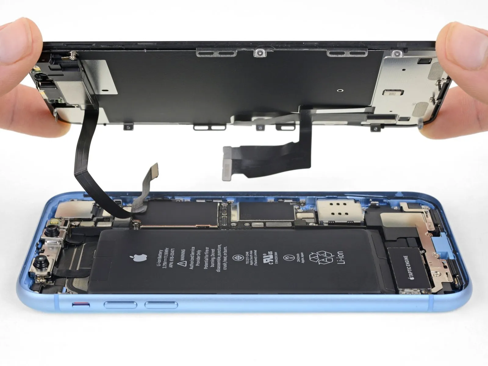
- Detach the display unit from the device.
- If a replacement of the waterproof adhesive seal bordering the display is desired, halt the reassembly process at this juncture.
Step 26 | Unscrew the earpiece speaker

- To detach the speaker/sensor component from the display's rear surface, it is necessary to eliminate the four fastening screws.
- A quantity of two screws, each with a 1.6 mm Phillips head, are required for removal.A single screw, utilizing a 2.3 mm Phillips head, must also be unscrewed.
- Additionally, one screw featuring a 1.2 mm Y000 head needs to be taken out.The speaker/sensor assembly is affixed using these screws.
- Carefully unscrew each fastener to avoid damaging surrounding components.Ensure proper screw head type is used to prevent stripping.
Step 27 | Flip the speaker over


- Employing tweezers, carefully rotate the speaker assembly, positioning it so the underside faces away from the display's upper boundary.
- The speaker is secured by a delicate flex cable; exercise caution to prevent any stress or harm to this connection.
Step 28 | Heat the front sensor strip

- To loosen the adhesive that holds the sensors in place, apply heat using a hairdryer, heat gun, or iOpener to the display's upper front surface for approximately one minute.
- Caution is required to prevent damage.Excessive heat exposure to the display assembly should be avoided.
Step 29 | Pry up the microphone


- Employing a spudger's planar edge, meticulously insert it beneath the flexible cable situated adjacent to the microphone.Apply a slight rotational force to disengage the microphone, exercising caution to prevent undue stress or harm to the flex cable.Should separation prove challenging, utilize the spudger's pointed tip to complete the microphone's detachment from its corresponding recess within the front panel.
- Increased thermal energy may be necessary to facilitate microphone dislodgement if initial attempts are unsuccessful.
- The flexible cable's integrity must be maintained throughout the separation process to avoid functional impairment.Gentle manipulation is essential; forceful actions could compromise the flex cable's delicate construction.A spudger is the recommended tool for this procedure due to its design, which minimizes the risk of scratching or damaging surrounding components.
Step 30 | Pry up the proximity sensor


- Commencing with the left side and proceeding towards the right, insert an opening pick to gain access.Position the pick's tip under the flexible cable and also beneath the proximity sensor and flood illuminator module assembly.Employing subtle movements, elevate the module by disengaging it from its corresponding recess within the front panel.
- To facilitate access, supporting the speaker while working can be advantageous; however, avoid applying tension to the delicate flex cable.
- The thin flex cable requires careful handling to prevent damage during the repair process.Maintaining a secure grip on the speaker prevents obstruction during module separation.Separating the module necessitates a cautious approach to avoid stressing the flex cable's integrity.
Step 31 | Remove the ambient light sensor bracket


Employing tweezers, carefully maneuver the diminutive bracket in a vertical direction to disengage it from the ambient light sensor.The ambient light sensor is the component from which the bracket must be removed.Ensure the bracket's removal is a linear, upward motion to prevent damage.
Step 32 | Lift the ambient light sensor


- Employ tweezers to gently move the ambient light sensor, dislodging it from its designated slot within the display panel.Should the sensor resist separation after a brief attempt, increased heat application may be necessary to facilitate removal, followed by another attempt.The ambient light sensor is connected to the broader sensor assembly through a delicate flex cable.
- Exercise caution to prevent undue stress or potential damage to this extremely thin flex cable.
- Careful manipulation is required to avoid compromising the integrity of the flex cable's connection.The sensor's attachment is maintained by a very thin flex cable, demanding meticulous handling.To release the sensor, use tweezers to carefully maneuver it and elevate it from its position within the display's recess.
Step 33


- Following complete removal of the ambient light sensor, as depicted in the initial image, proceed to the subsequent instructions.
- Should the white diffuser strip become separated but remain lodged within the display, as illustrated in the second image, employ a thin blade or pry tool to gently dislodge it from the upper boundary.Applying supplemental heat beforehand can potentially simplify the process of extracting the diffuser.For reassembly, initially position the diffuser within the display, confirming correct orientation; the front-facing surface is visible in the first image, while the rear-facing surface is shown in the third.
- Subsequently, place the ambient light sensor atop the diffuser.Maintaining the sensor's position is necessary while securing the earpiece/sensor assembly with screws.Once the screws are fully tightened, the sensor will remain fixed and function as intended.The thin blade or pry tool should be used with caution to avoid damage to the display surface.Ensure the front-facing side of the diffuser aligns correctly before securing the ambient light sensor.
- Proper alignment of the diffuser and sensor is crucial for optimal ambient light sensing performance.
Step 34 | Remove the speaker + front sensors


- Detach the earpiece speaker and front sensor subassembly from the device.
- Verify the alignment of the black plastic component housing the proximity sensor and flood illuminator during reassembly.
The proximity sensor facilitates close-range detection.
The flood illuminator provides illumination for improved image capture in low-light conditions.Ensure the module's placement prevents any adhesive from blocking the functionality of the proximity sensor or flood illuminator.
Step 35 | Unscrew the LCD shield plate


- Employ a Y000 driver for the removal of the 1.1 mm screws that fasten the LCD shield.The LCD shield is held in place by three screws positioned along the edge closest to the display cables.An additional two screws secure the shield on the opposing side.
Apply consistent pressure with the driver as you rotate each screw.
Should increased force be necessary, a spudger can be used to stabilize the screws from the rear, preventing shield deformation.This bracing technique allows for greater torque application without bending the LCD shield. - Ensure the driver is fully seated within the screw head during the unscrewing process.
Step 36


- Eliminate the residual 1.1-millimeter Y000 screws.These screws are positioned along the upper and lower borders of the LCD shield.Specifically, two screws are located proximate to the camera apertures.
Additionally, two screws are situated at the lower corners of the device.
Complete removal of these fasteners is necessary for proceeding with the repair.Carefully extract all identified screws to prevent damage to surrounding components.
Step 37 | Add a little heat


To loosen the adhesive holding the display cables to the LCD shield, direct a small amount of heat using an iOpener (or a hairdryer/heat gun) onto the rear surface of the display.The application of heat facilitates the separation of the adhesive bond.Employing an iOpener, hairdryer, or heat gun allows for targeted warming to ease adhesive removal.
Step 38 | Unstick the display cables


- Introduce a prying tool into the space located between the display assembly's connecting wires and the LCD shield.
- Advance the tool towards the lower boundary of the display to initiate the disengagement of the connecting wires.
- Cease the separation process once the termination point of the initial connecting wire is attained.
Step 39 | Separate the two cables


- Reintroduce the opening tool, positioning it this time in the space located between the two cable harnesses.
- Advance the tool towards the lower display boundary to disengage the cable connectors.
Step 40


To prevent damage, detach each cable by grasping it close to the 90-degree angle and separating the connectors.
Step 41


Step 42 | Lift the shield plate


Step 43


- To detach the LCD shield, grasp its superior border and pivot it upwards slightly.
- Employing a spudger tool, apply subtle pressure to the display cable's inferior section.This pressure facilitates the cable's passage through the opening within the LCD shield’s structure.The manipulation ensures proper disengagement of the display cable from its secured position.
Step 44


Step 45 | Separate the display cable


- To gain a clearer view of the display cable's attachment, elevate the LCD shield to a more acute angle.The display cable's adherence to the rear housing becomes visible as the shield's position is adjusted.Employing a spudger tool, carefully insert it into the space formed between the LCD shield and the display cable.
- A spudger, a specialized prying tool, is necessary for this separation procedure.Complete the detachment of the LCD shield and display cable by sliding the spudger along their interface.Ensure the display cable is fully disengaged from the LCD shield to prevent damage.The separation must be thorough to avoid any lingering connection between the components.Carefully maneuver the spudger to prevent accidental damage to the delicate display cable during the separation process.
Step 46 | Check the EMI fingers


- Carefully raise the LCD shield, observing the metallic projections located along its lower border.These projections, situated at the lower edge, are crucial for proper alignment.During the reassembly process, confirm that these projections, also known as EMI fingers, are properly seated.
- Ensure the EMI fingers are correctly positioned within the LCD frame.Refer to the provided diagram to verify the correct placement of these components within the LCD frame.Proper insertion of the metal prongs into the LCD frame is essential for electromagnetic interference (EMI) shielding.
Step 47 | Remove the shield

Carefully detach the LCD shield component.The LCD protective covering must be separated from the device.Disconnection of the LCD shield is required for subsequent repair steps.
Step 48

The display panel and touch-sensitive digitizer assembly are the only components still attached.Specifically, the liquid crystal display and its integrated digitizer are the remaining parts.These components, comprising the LCD and digitizer, are the sole elements presently affixed.