iPhone XS Earpiece Speaker and Front Sensor Assembly Replacement
Adhere to the instructions detailed within this manual to detach, relocate, and/or substitute the earpiece speaker and front sensor assembly within your iPhone XS. The assembly incorporates the earpiece speaker, a microphone, an ambient light sensor, a flood illuminator, and a proximity sensor.
Because this assembly is uniquely linked to your specific iPhone during manufacturing, its transfer from the original display to a replacement display is essential during any display service.
- Theflood illuminatoris an integral element of the biometric Face ID security system. Malfunction or improper installation of this component will result in the inability to use Face ID.
- Substituting this component with a replacement part will also disable Face ID functionality; therefore, exercise heightened caution to prevent damage to any of these components throughout the repair process.
- Restoration of Face ID functionality is exclusively achievable by Apple if damage occurs.
Step 1 | Pentalobe Screws
- As a preliminary precaution, ensure your iPhone's battery level drops below 25% before commencing the repair process.A fully charged lithium-ion battery presents a significant hazard, as it carries the potential for ignition or forceful rupture if it sustains accidental damage.
- To ensure safety and prevent electrical shorts, completely power down your iPhone prior to starting the disassembly.
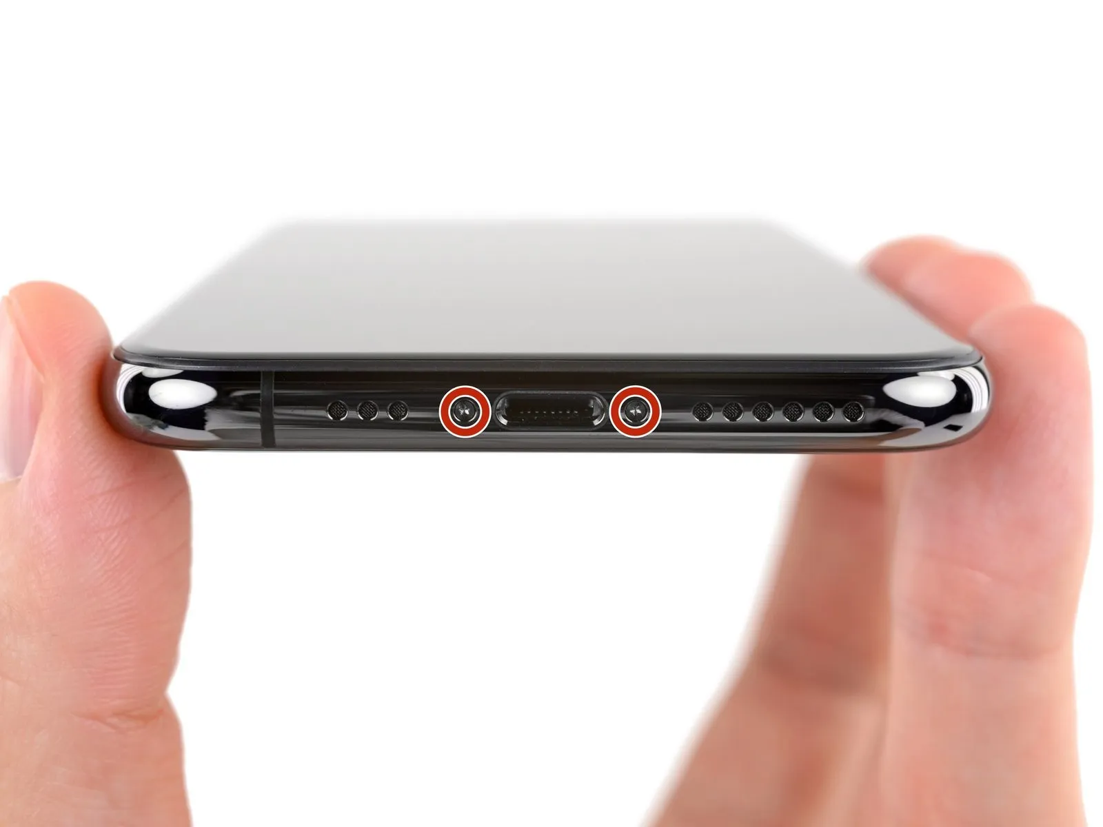
- Using a suitable tool, carefully unscrew and remove the pair of pentalobe screws, each measuring 6.9 mm in length, located along the iPhone's lower edge.
- Separating the iPhone's display assembly will inevitably damage the integrated waterproof barriers; therefore, acquire replacement seals beforehand to maintain water resistance, or exercise extreme caution to prevent moisture ingress if you intend to reassemble the device without new seals.
Step 2 | Mark your opening picks


- To avoid potential harm to your device, ensure the opening pick isn't inserted beyond its intended depth; this procedure will help you identify a safe insertion point.
- Determine the distance of3 mmfrom the pick's leading edge and use a permanent marker to create a visible indicator on the opening pick.
- For additional reference, consider marking the pick's other corners with varying measurements.
- As another option, affix a coin to the pick's shaft,3 mmaway from its tip.
Step 3 | Tape over any cracks


- To mitigate additional damage and potential injury while repairing a fractured iPhone display, secure the glass fragments with adhesive tape.
- Apply multiple layers of transparent packing tape across the iPhone's screen surface, ensuring complete coverage of the entire front face.
- Always utilize eye protection, specifically safety glasses, to guard against glass shards that may become dislodged during the repair process.
- Should the suction cup fail to adhere properly during subsequent steps, create a handle by folding a durable tape, like duct tape, and employ it to gently raise the screen.
- As a last resort, secure the suction cup to the screen’s surface using superglue to facilitate lifting.
Step 4 | Anti-Clamp instructions


- The following three procedures illustrate the function of the Anti-Clamp, a specialized tool developed to simplify the initial opening process; if this tool is not available, proceed to the subsequent three steps for an alternative approach.
- Detailed instructions regarding the Anti-Clamp's operation can be found in a separate, dedicated guide.
- Grasp theblue handleand move it in a rearward direction to disengage the Anti-Clamp's securing arms.
- Carefully position the arms across either the left or right side of your iPhone.
- Place the suction cups close to the lower edge of the iPhone, ensuring one is situated on the front surface and the other on the rear.
- Apply pressure by compressing the cups together to establish a secure suction hold on the intended area.
- Should the iPhone's surface prove excessively slick, preventing adequate adhesion by the Anti-Clamp, applying adhesive tape can provide a more textured surface for improved grip.
Step 5


- To engage the locking mechanism, draw the blue handlein a forward direction.
- Rotate the handlethrough a full 360-degree rotation, or until you observe the suction cups beginning to deform.
- Confirm that the suction cups maintain their parallel orientation; should they exhibit any signs of displacement, gently release the suction cups and reposition the arms.
Step 6


- Employ a heat source to warm aniOpenerand carefully guide it between the arms of the Anti-Clamp device.
Alternative heating methods, such as a hair dryer, heat gun, or hot plate, are acceptable; however, exercise caution as excessive heat can potentially harm the display assembly and/or the internal battery. - Position theiOpenerin a folded configuration, ensuring it rests along the lower edge of the iPhone’s casing.
- Allow a sixty-second interval to permit the adhesive bond to soften and create a discernible separation.
- Introduce an opening pick into the created space located beneath the screen and the plastic bezel, specifically avoiding direct contact with the screen’s surface.
- Should the Anti-Clamp fail to generate a satisfactory gap, increase the heat applied to the region and rotate the handle by ninety degrees.
Limit rotational increments to ninety degrees, and incorporate a sixty-second pause between each adjustment; allow the Anti-Clamp and time to facilitate the separation process. - Proceed past the subsequent three instructions.
Step 7
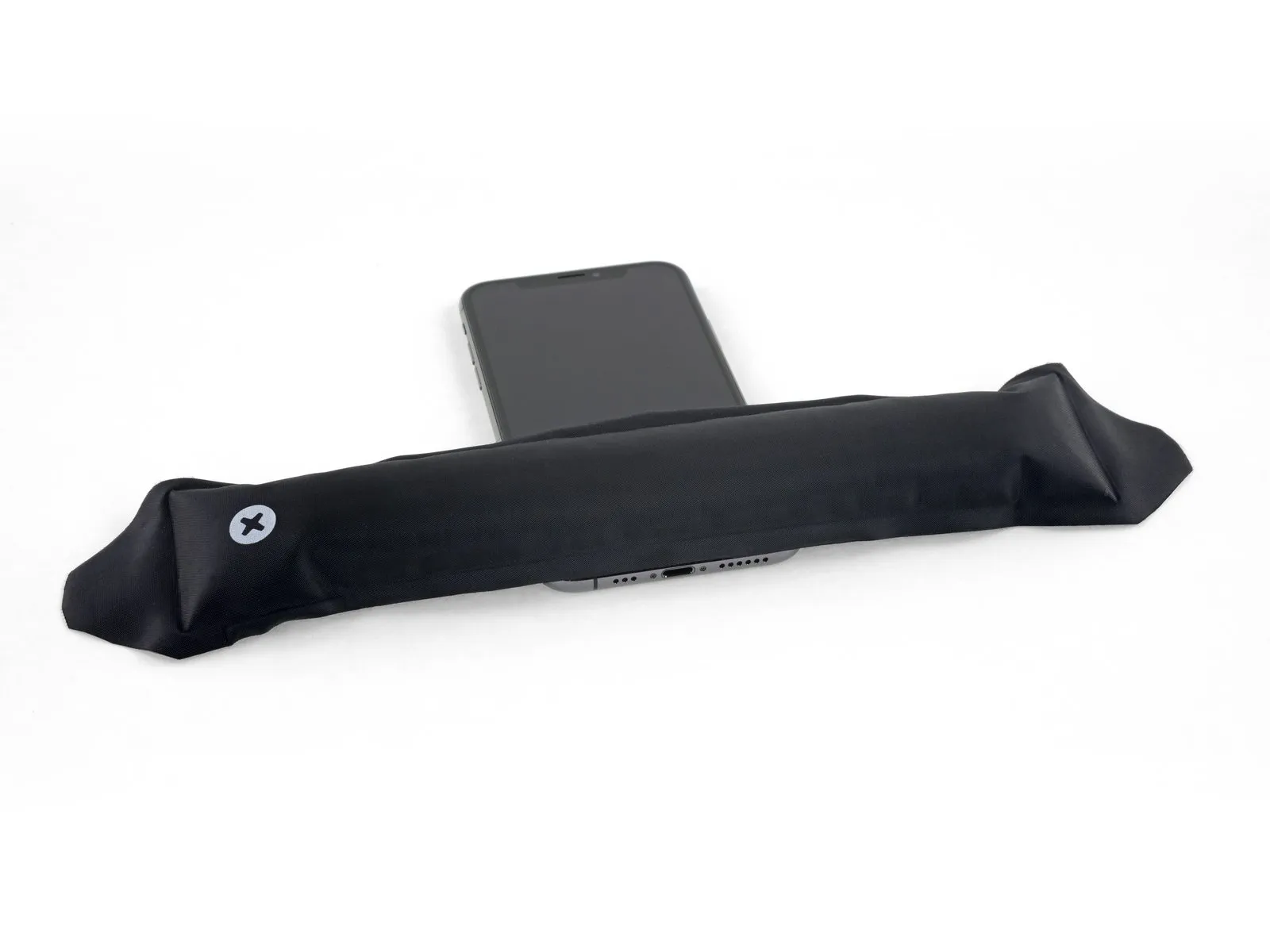
Applying warmth to the iPhone's bottom edge facilitates the loosening of the adhesive that holds the display in place, which simplifies the opening process.
Employ ahairdryerorheat gunor alternatively, utilize aniOpenerand direct its heat towards the iPhone's lower edge for approximately one minute to reduce the adhesive's tackiness.
Step 8
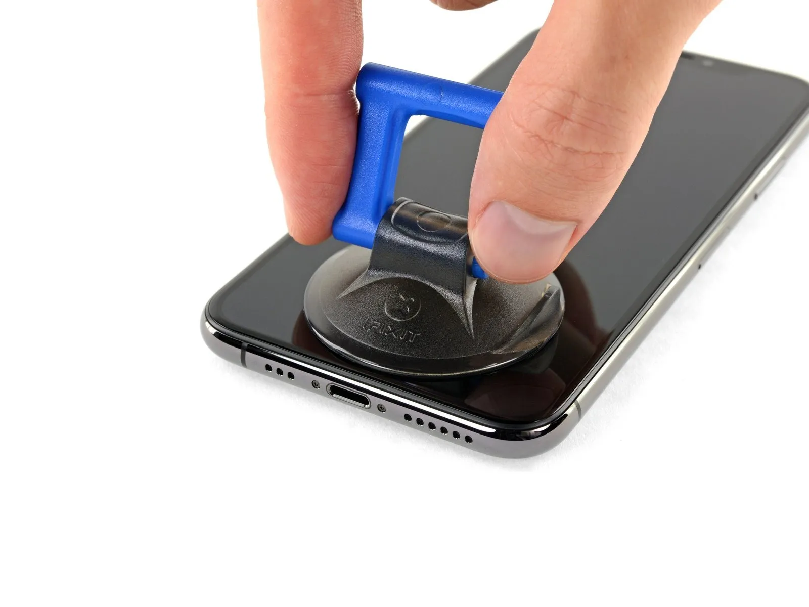
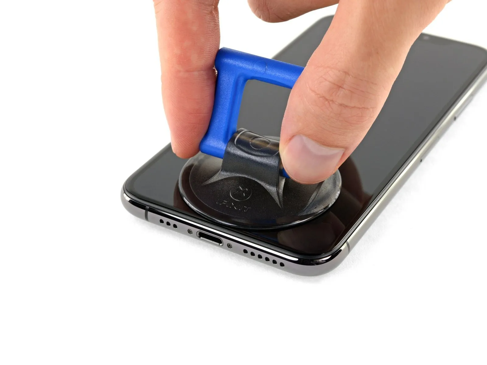
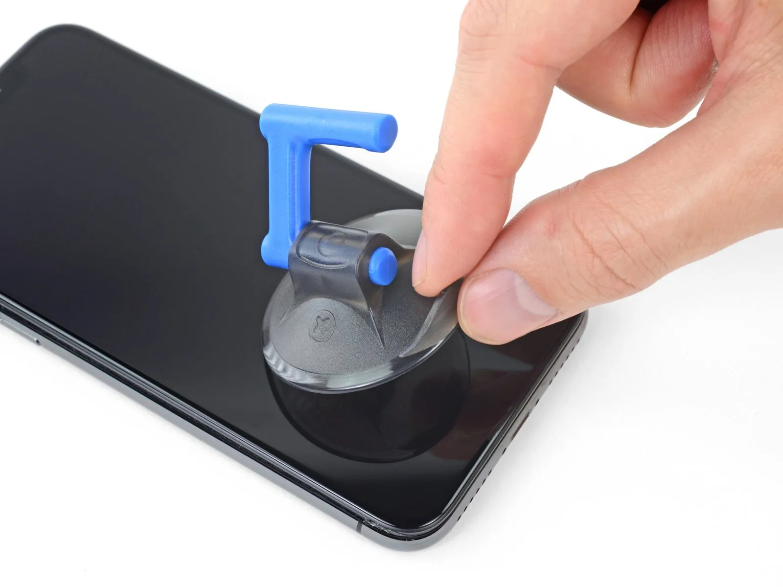
When employing a solitary suction handle, position it against the lower perimeter of the device's frame, ensuring it does not contact the rounded glass surface.
Step 9
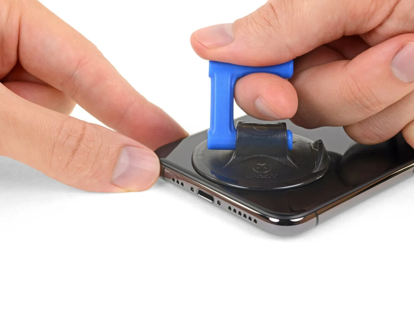
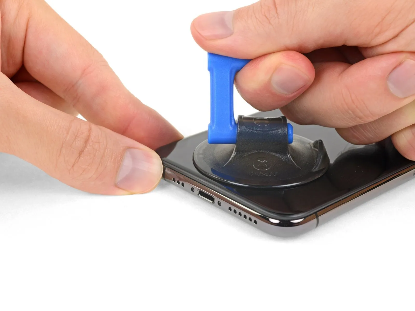
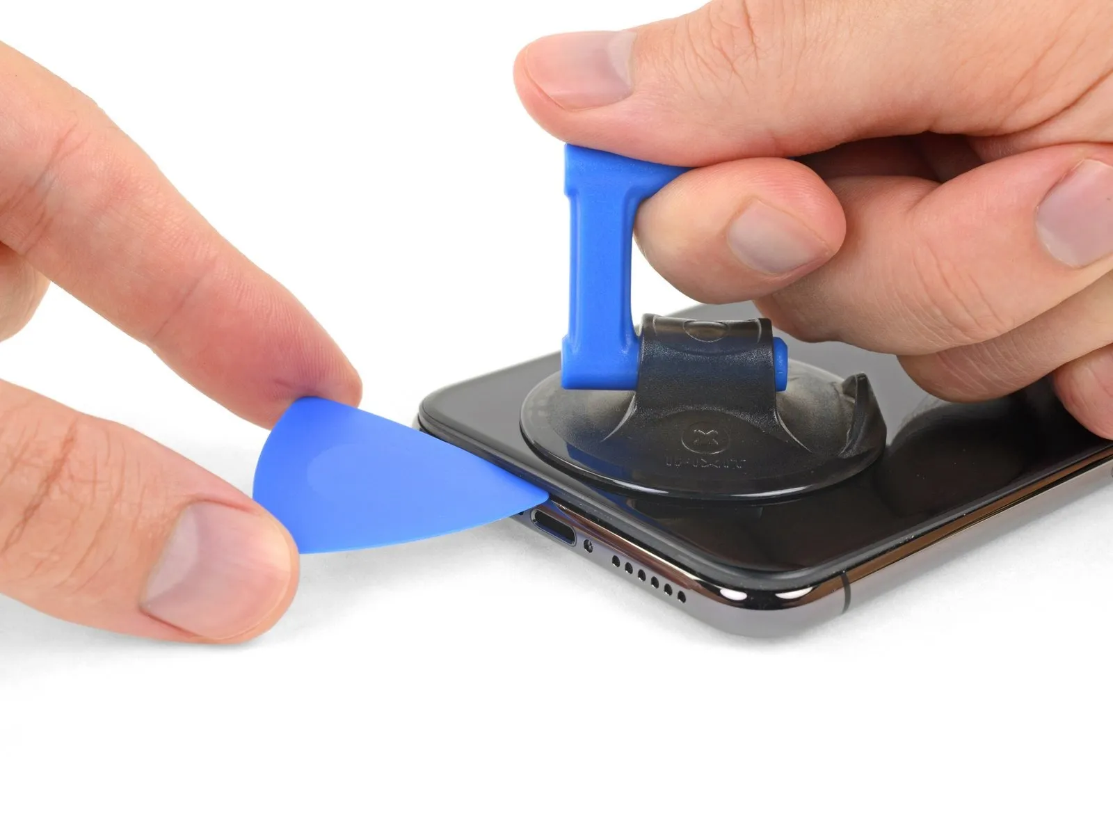
- Apply steady, forceful upward pressure to the suction cup to generate a small separation between the front panel assembly and the device's rear casing.
- Carefully slide an opening tool into the space formed beneath the display screen and the surrounding plastic trim, ensuring it does not contact the screen's surface directly.
- Due to the robust, waterproof adhesive securing the display, establishing this initial separation requires considerable force; should you encounter difficulty, apply additional heat and gently oscillate the screen in an upward and downward motion to reduce the adhesive's strength until a sufficient gap is achieved for tool insertion.
Step 10
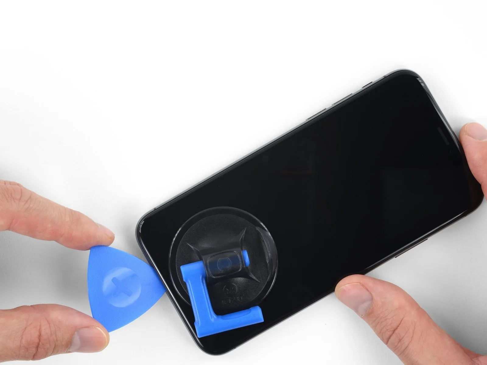
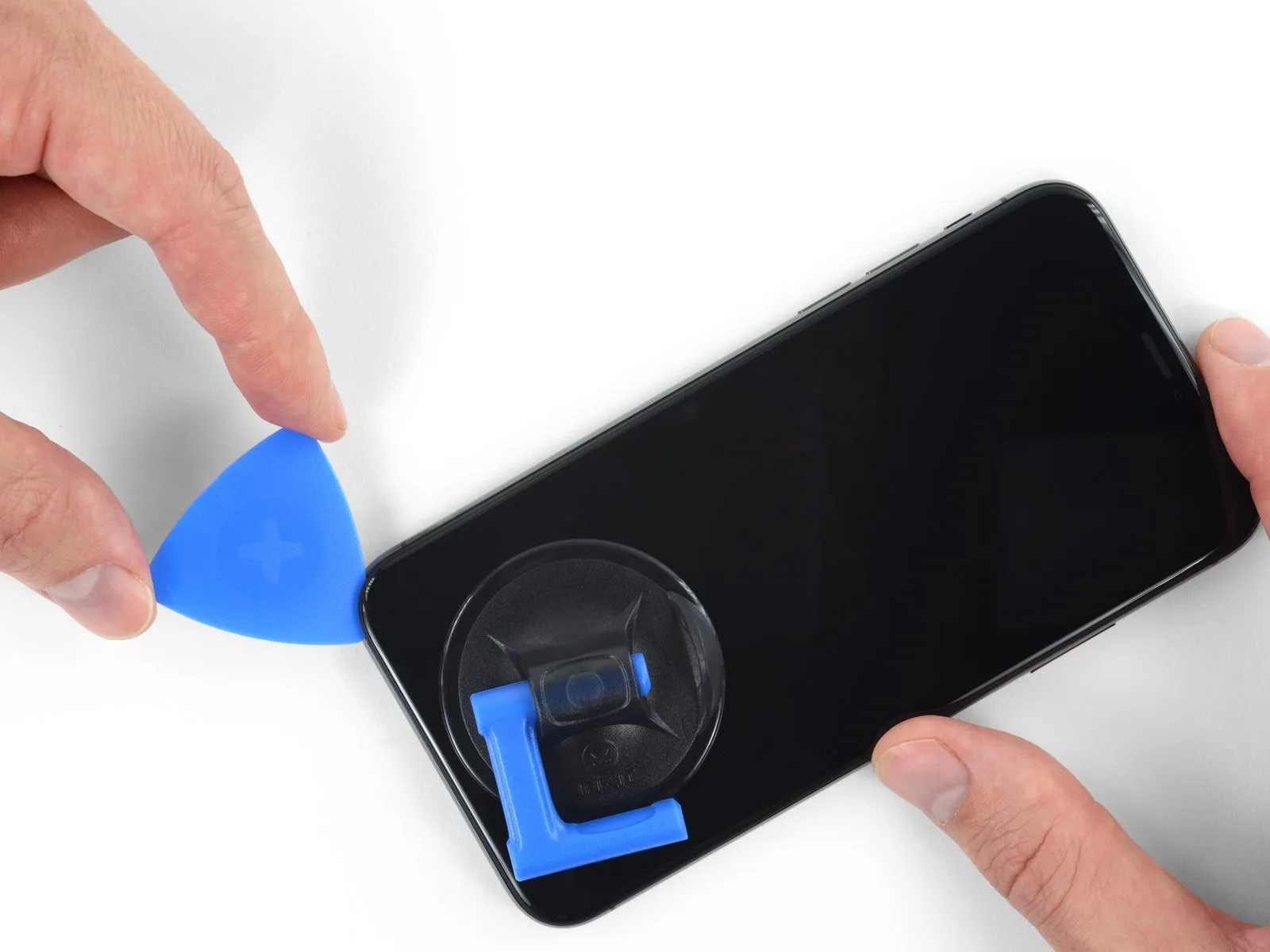
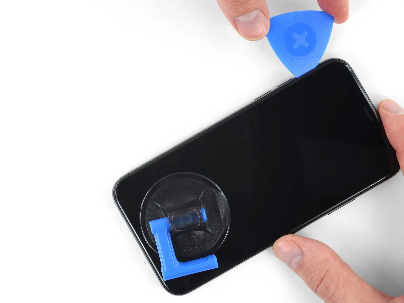
- Carefully maneuver the opening pick along the bottom-left corner of the iPhone, progressing upwards along the left side, to sever the adhesive securing the display assembly.
- Ensure the pick's insertion depth remains below3 mmto prevent potential harm to delicate internal parts.
Step 11 | Screen information
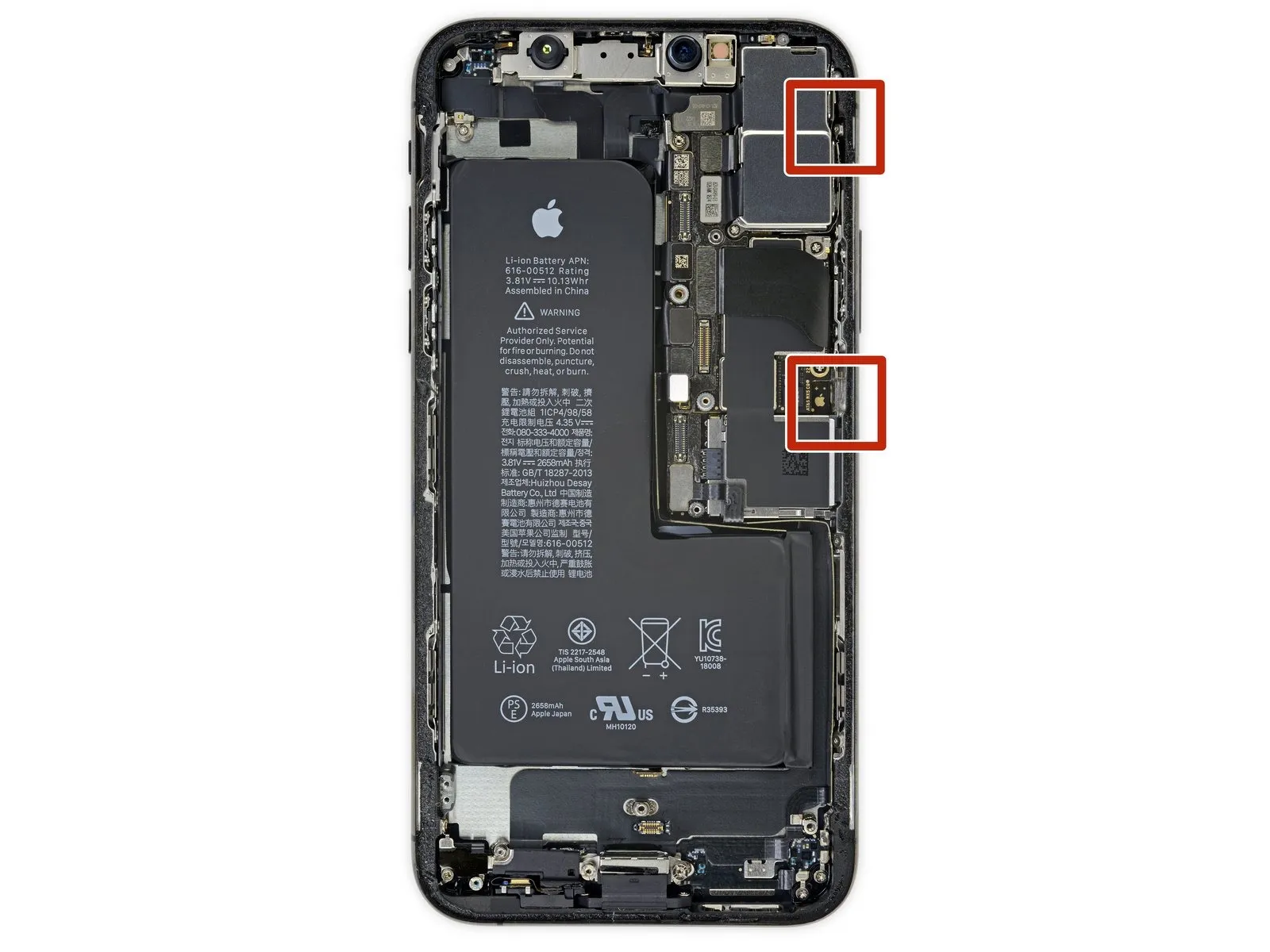
Along the right side of your iPhone, you'll find sensitive wiring; avoid inserting any tools in this area to prevent potential cable damage.
Step 12
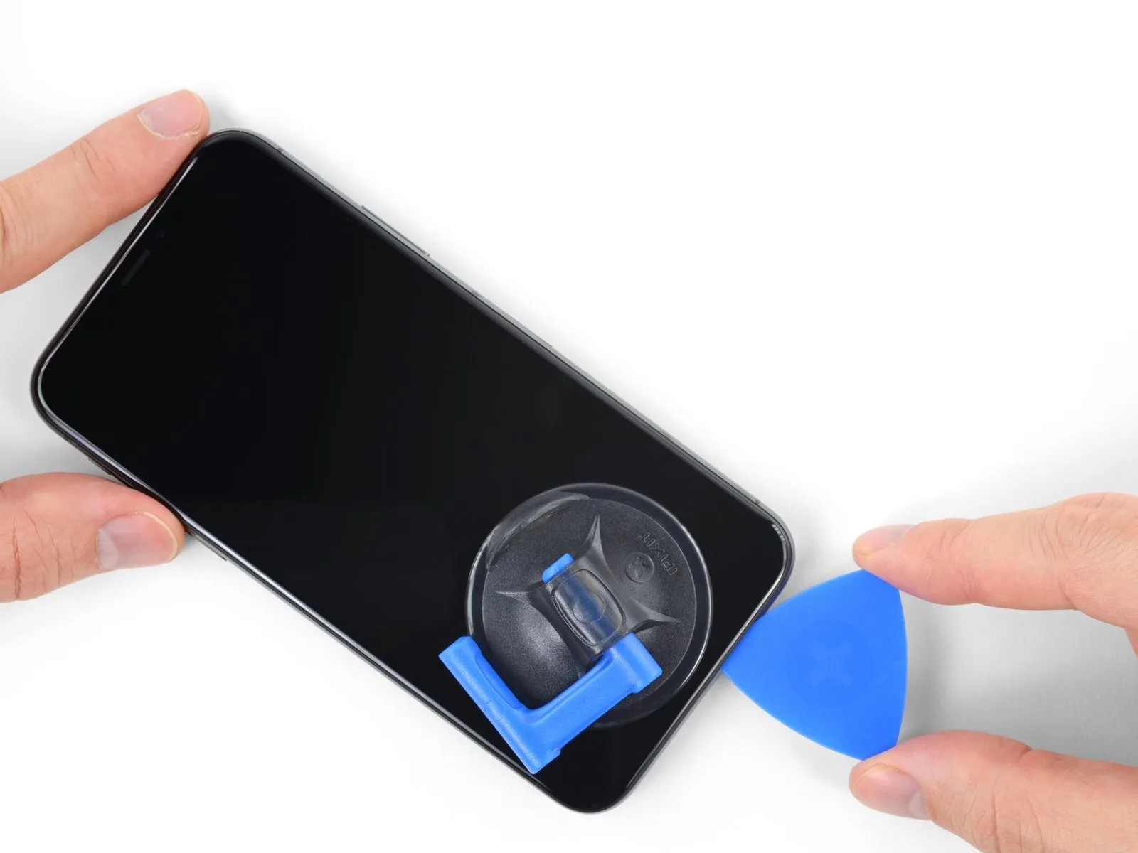
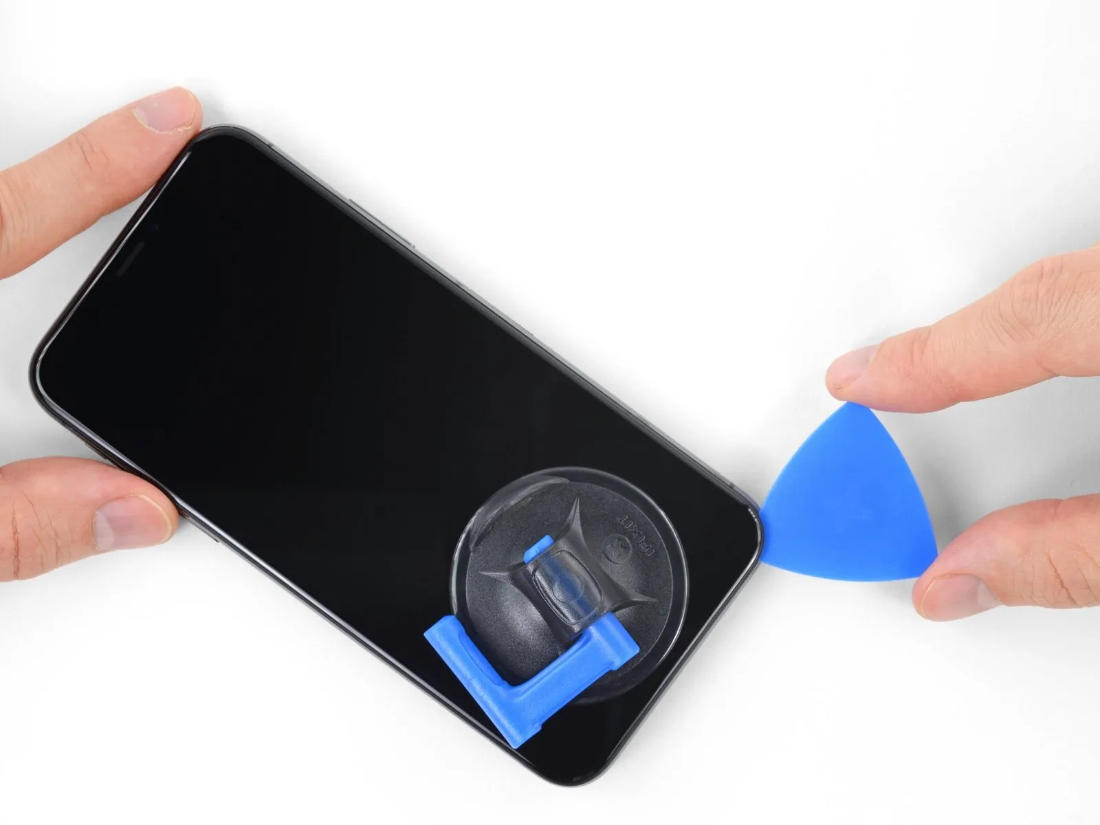
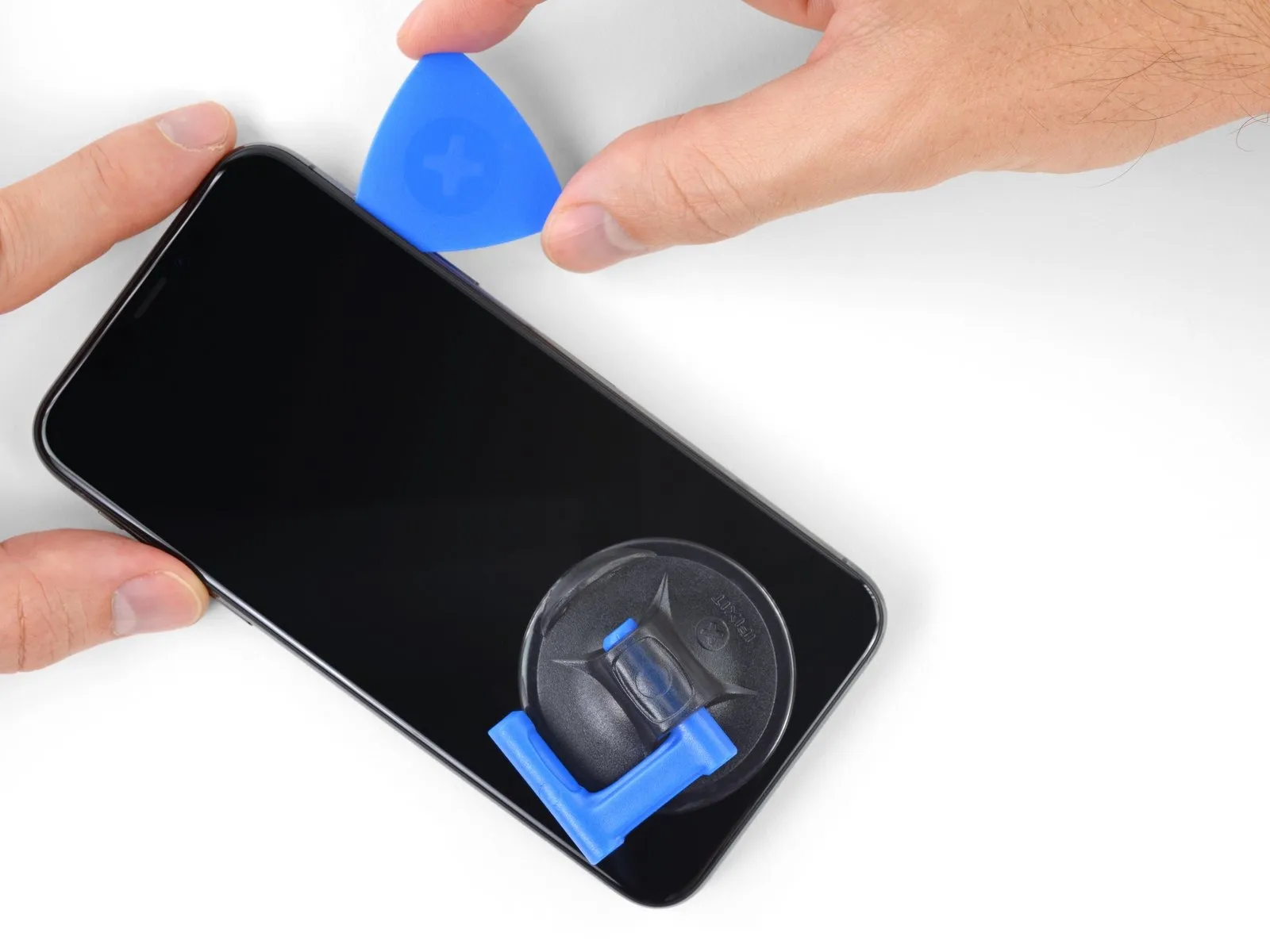
- To proceed with separating the adhesive, re-position your opening pick along the lower edge of the iPhone's enclosure and advance it upwards along the right side.
- Ensure your opening pick does not penetrate deeper than 3 mm, to prevent potential harm to the delicate display cable connections.
Step 13
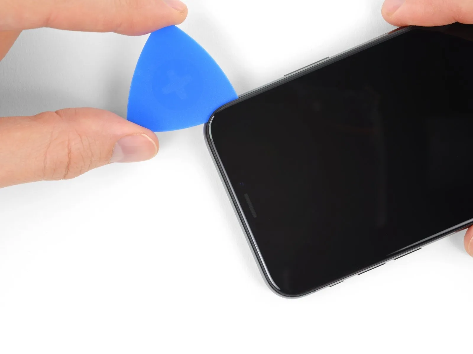
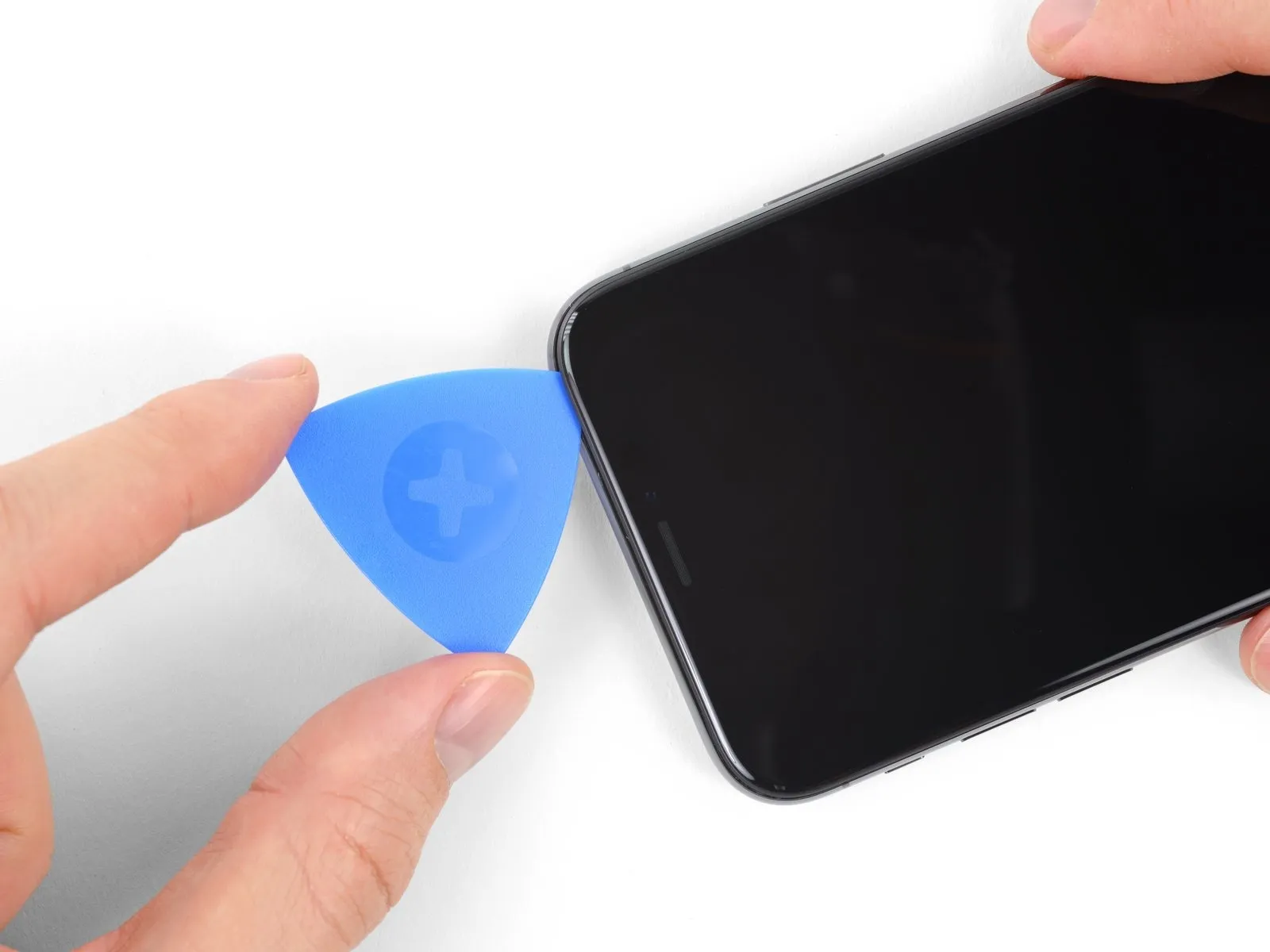
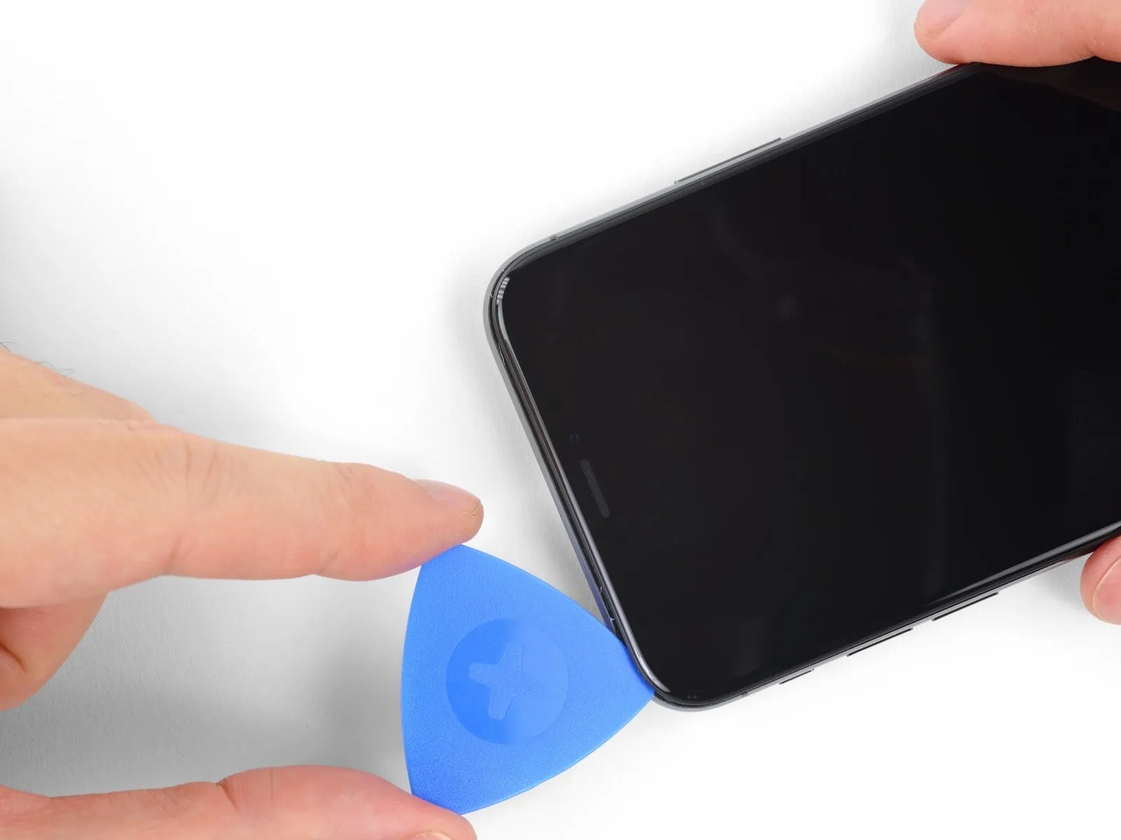
- Adhesive and retaining clips together fasten the display's uppermost border.
- Employing a specialized opening tool, maneuver it along the display's upper corner, applying slight downward traction or oscillation towards the Lightning connector's location.
- Excessive force applied to the retaining clips will result in their breakage; therefore, proceed with caution and deliberate care.
- Limit pick insertion depth to a maximum of 3 millimeters to prevent potential harm to the front panel sensor array.
- Continue the tool's movement to the opposing corner, severing any residual adhesive holding the display in place.
Step 14
Step 15
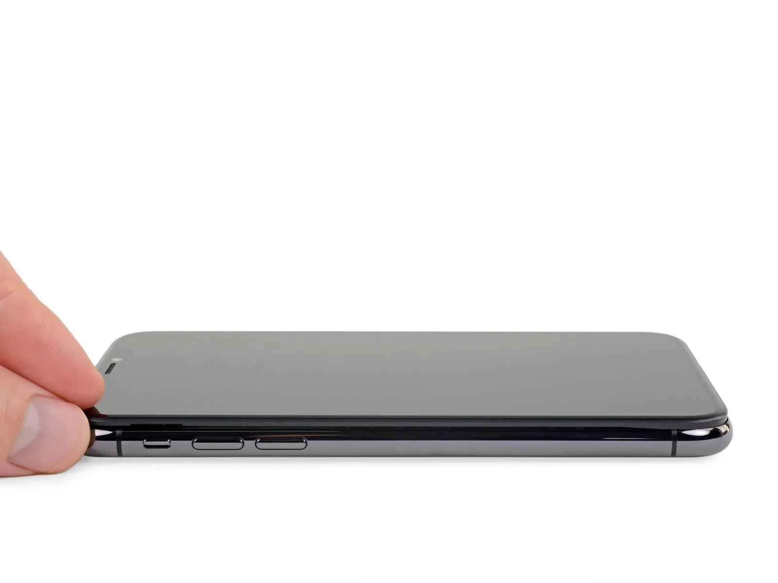
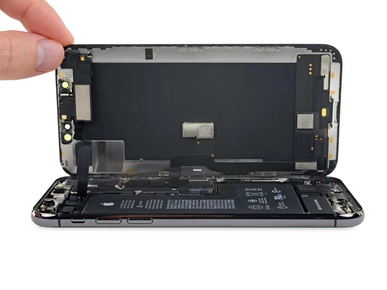
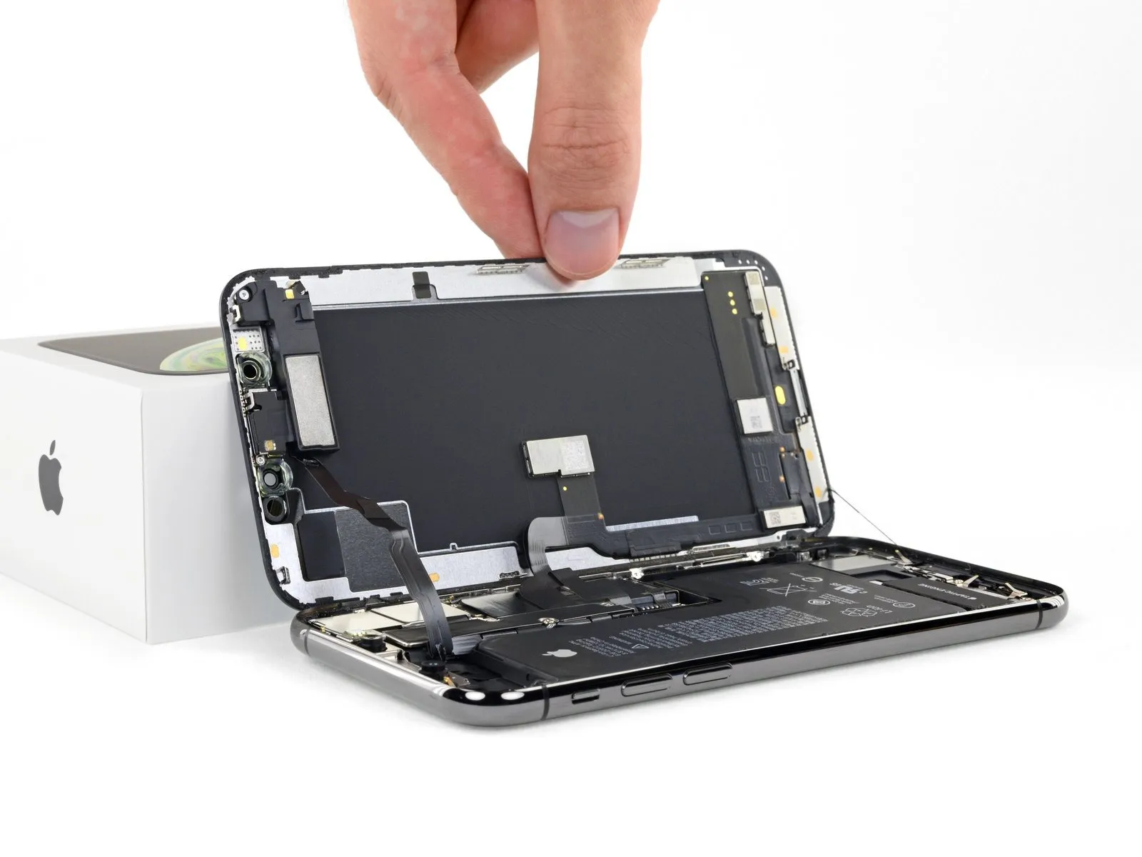
- To access the internal components of the iPhone, initiate the opening process by pivoting the display upwards from the left side, employing a motion similar to opening a book's cover.
- Refrain from completely detaching the display at this stage, because multiple delicate ribbon cables remain connected to the iPhone's logic board.
- Secure the display in an upright position using a support to maintain access to the device's internals.
- When reassembling the iPhone, position the display, ensure the clips along the upper edge are properly aligned, and then gently apply pressure to the top edge to secure it before fully engaging the remaining portion of the display. Should the display not seat easily, inspect the clips surrounding the display's perimeter for any deformation that might impede proper closure.
Step 16 | Display Assembly
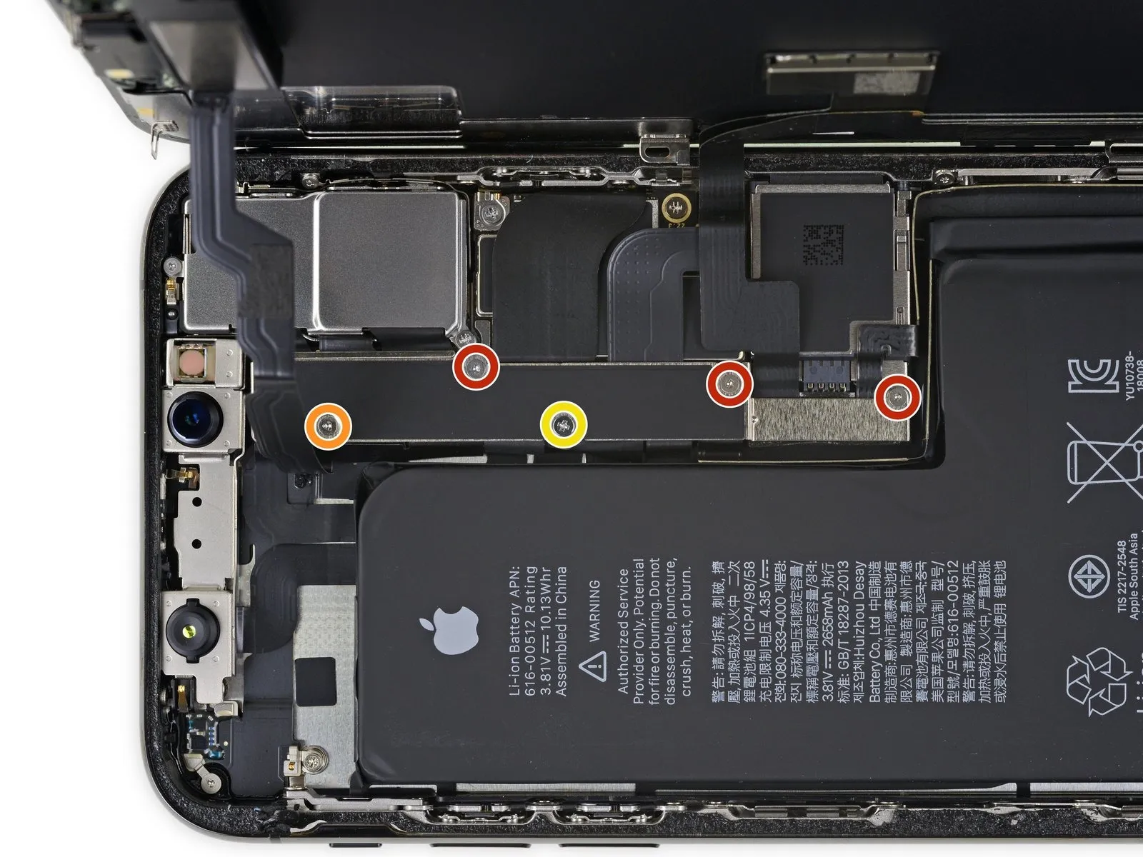
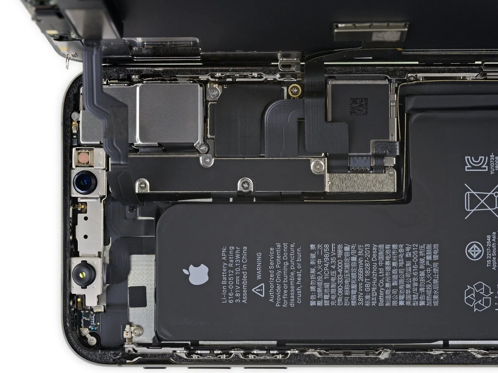
- Detach the bracket that holds the logic board connector by first removing five screws.
- Utilize three screws, each measuring 1.0 mm in length and requiring a Y000 screwdriver.
- A single 1.3 mm Y000 screw is also needed for this step.
- Additionally, a Phillips screw with a 3.7 mm head will be required.
Step 17
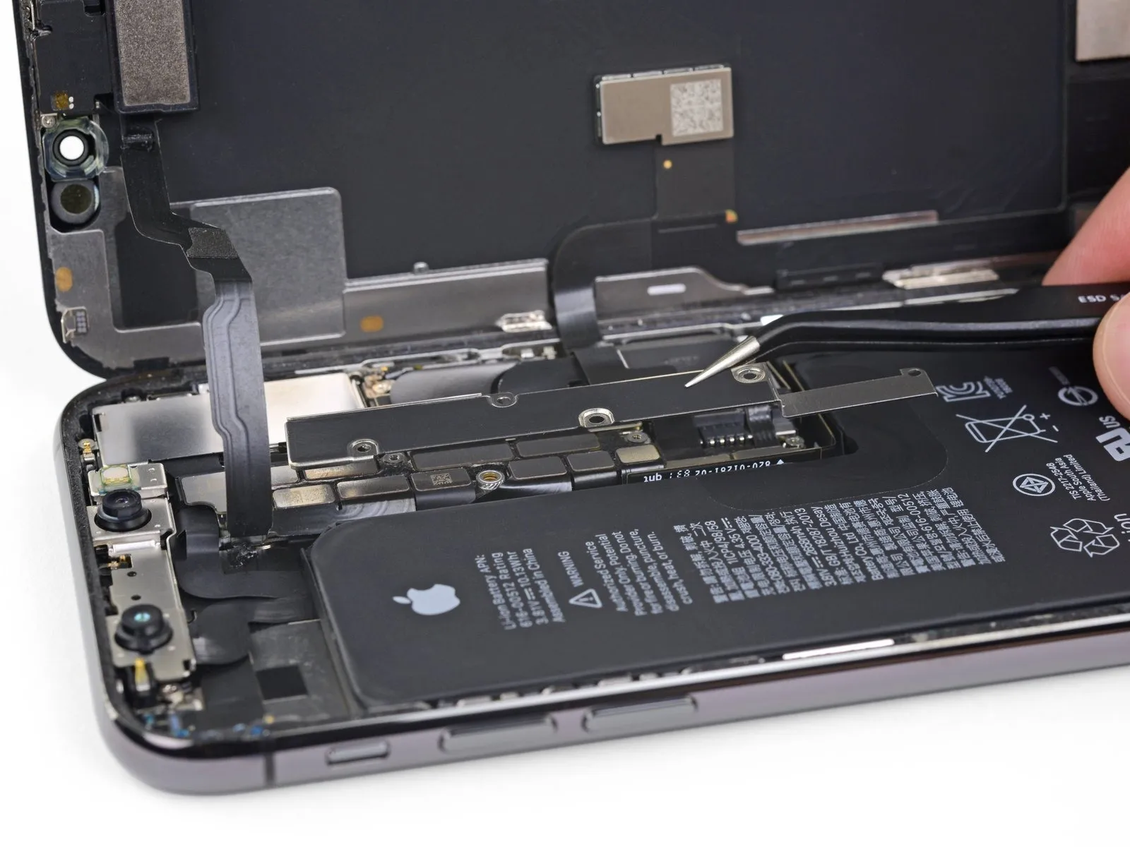
- Detach the bracket.
- Thebracketmight be subtly affixed; apply a careful, yet resolute upward force to disengage it.
As you reassemble the device, it's advisable to activate your iPhone and verify all operational capabilities prior to securing the display. Ensure the iPhone is fully powered off before proceeding with further repairs.
Step 18
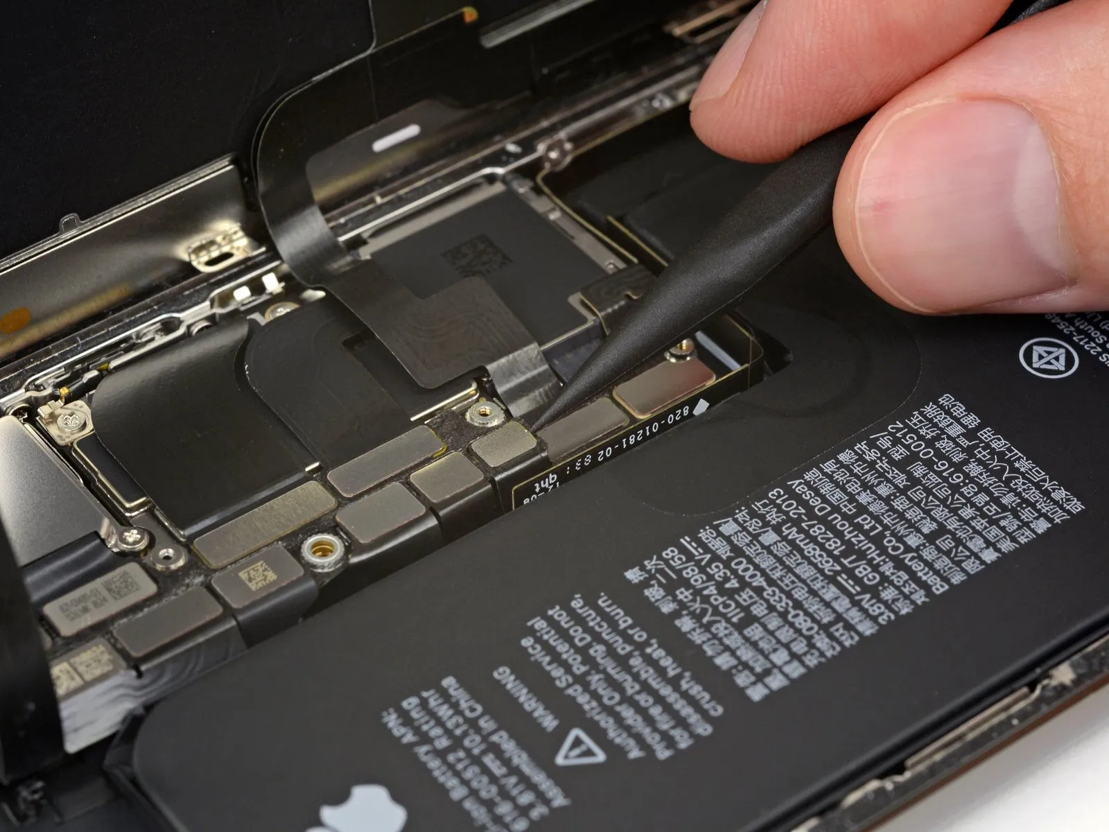
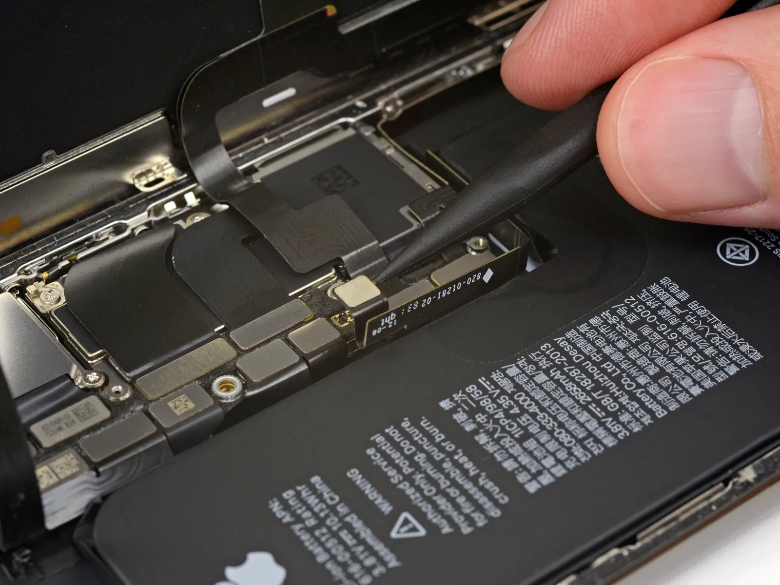
- Employ a spudgerAlternatively, a pristine fingernail can be utilized to lift the battery connector from its corresponding receptacle on the logic board.
- Exercise caution to avoid harming the black silicone sealant that encases this connector and others; this sealant offers supplemental defense against water and dust penetration.
- Slightly deflect the connector away from the logic board's surface to ensure it doesn't inadvertently establish an electrical connection with the socket, which could inadvertently power the device during the repair process.
Step 19
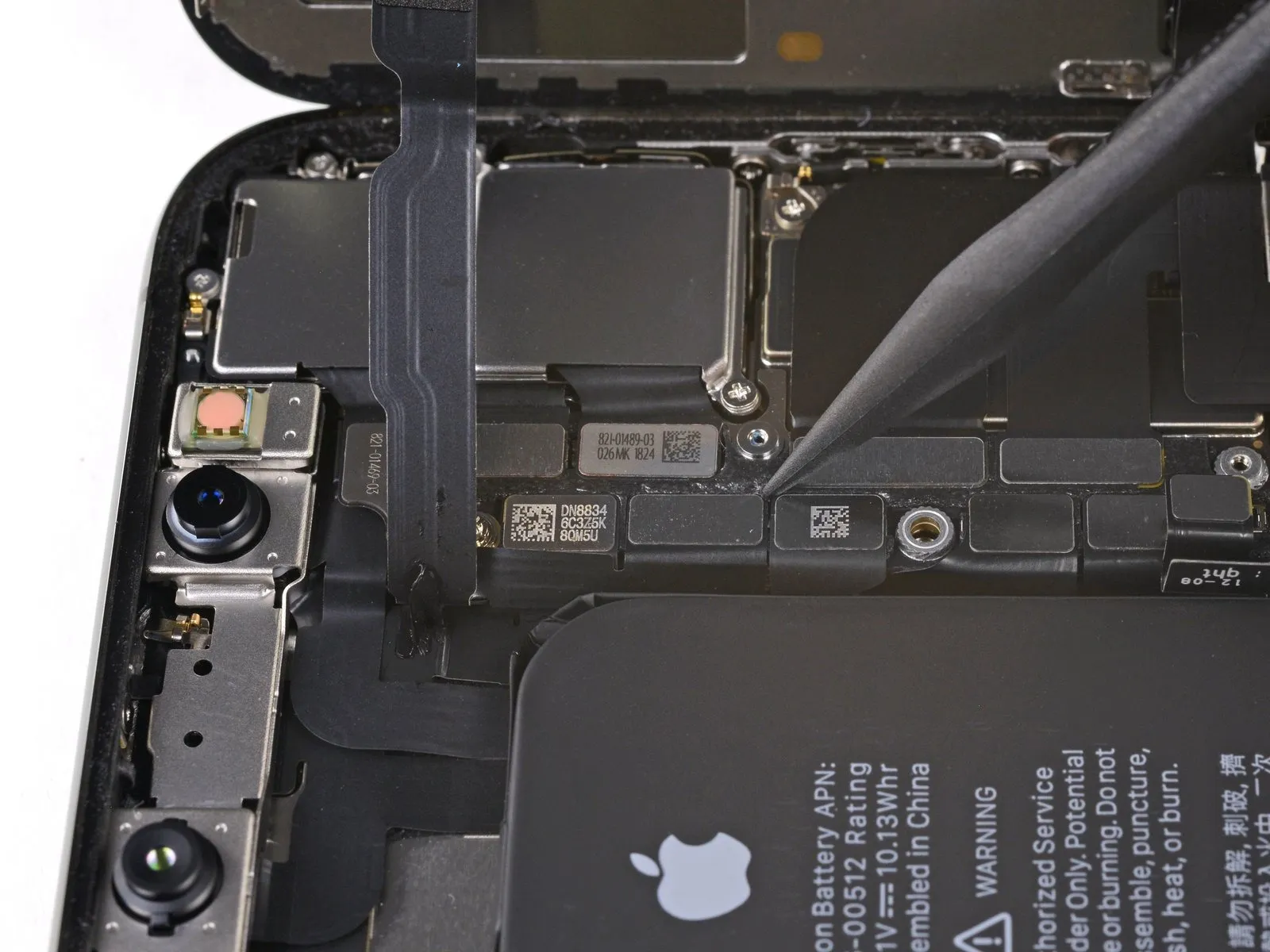
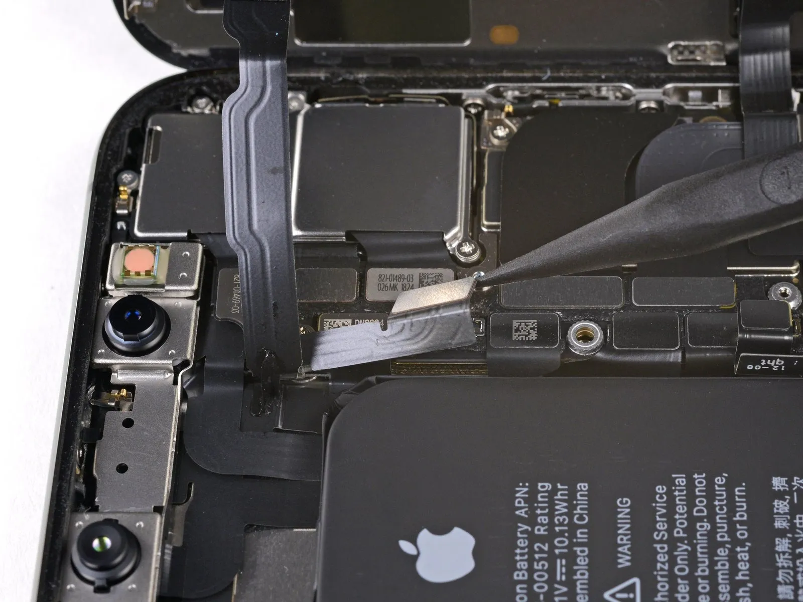
Employ a spudgerAlternatively, utilize a fingernail to carefully lift and detach the front panel sensor assembly connector.
Step 20
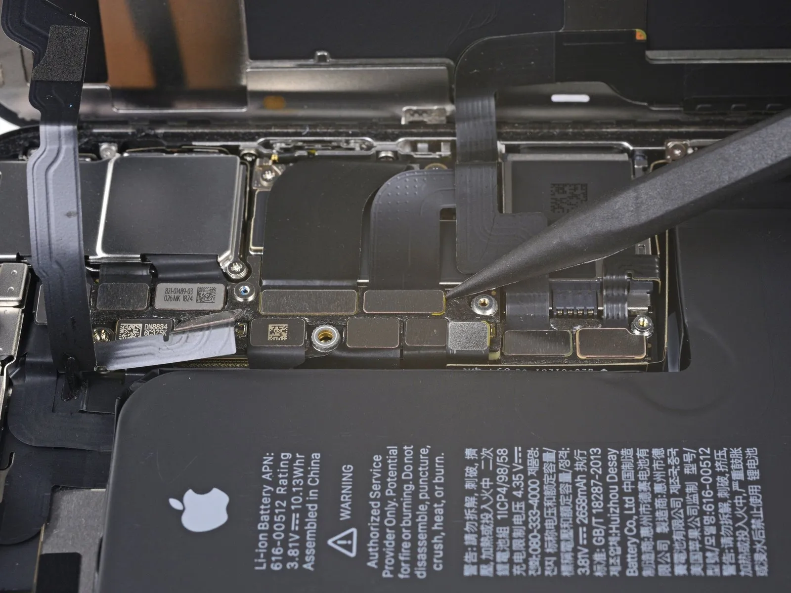
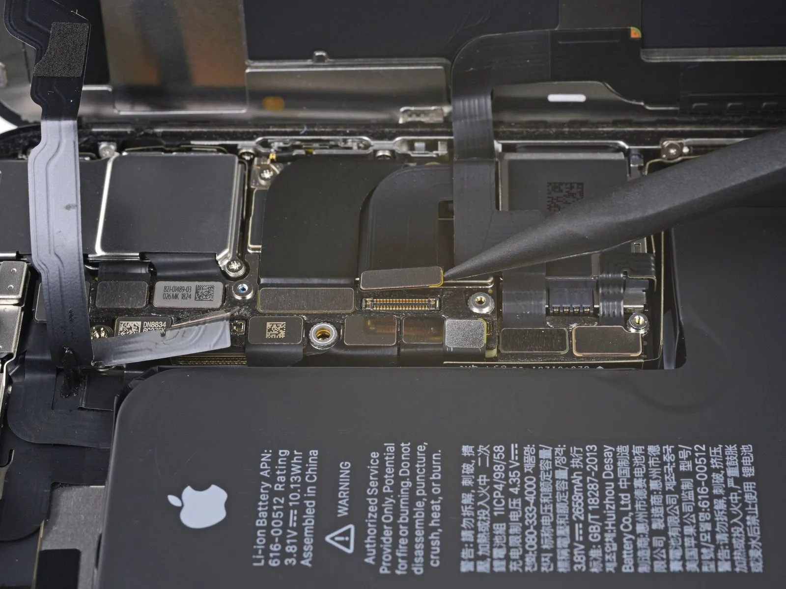
- Employ a spudgeror a fingernail to release the OLED panel cable connector's connection.
- For reattachment, position the connectors similarly, meticulously aligning and applying pressure to a single edge until a click is heard; then, repeat this process on the opposing edge. Avoid applying pressure to the central portion of the connector, as misalignment can result in pin bending and irreversible damage.
Step 21
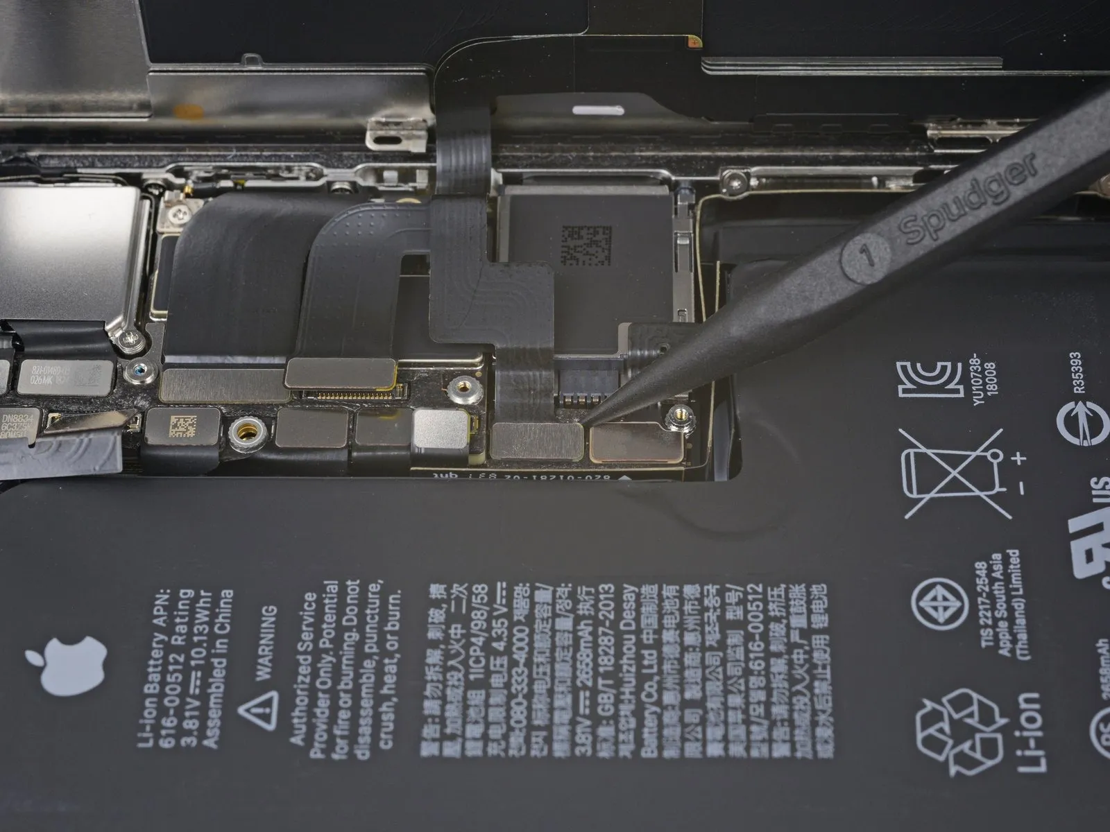

- Due to the connector's deeply set position, reattachment can be challenging; proceed deliberately and ensure precise alignment,
- then apply gentle pressure with your fingertip to secure it – initially one side, followed by the other.
- A distinct clicking sound should indicate successful engagement.
Step 22
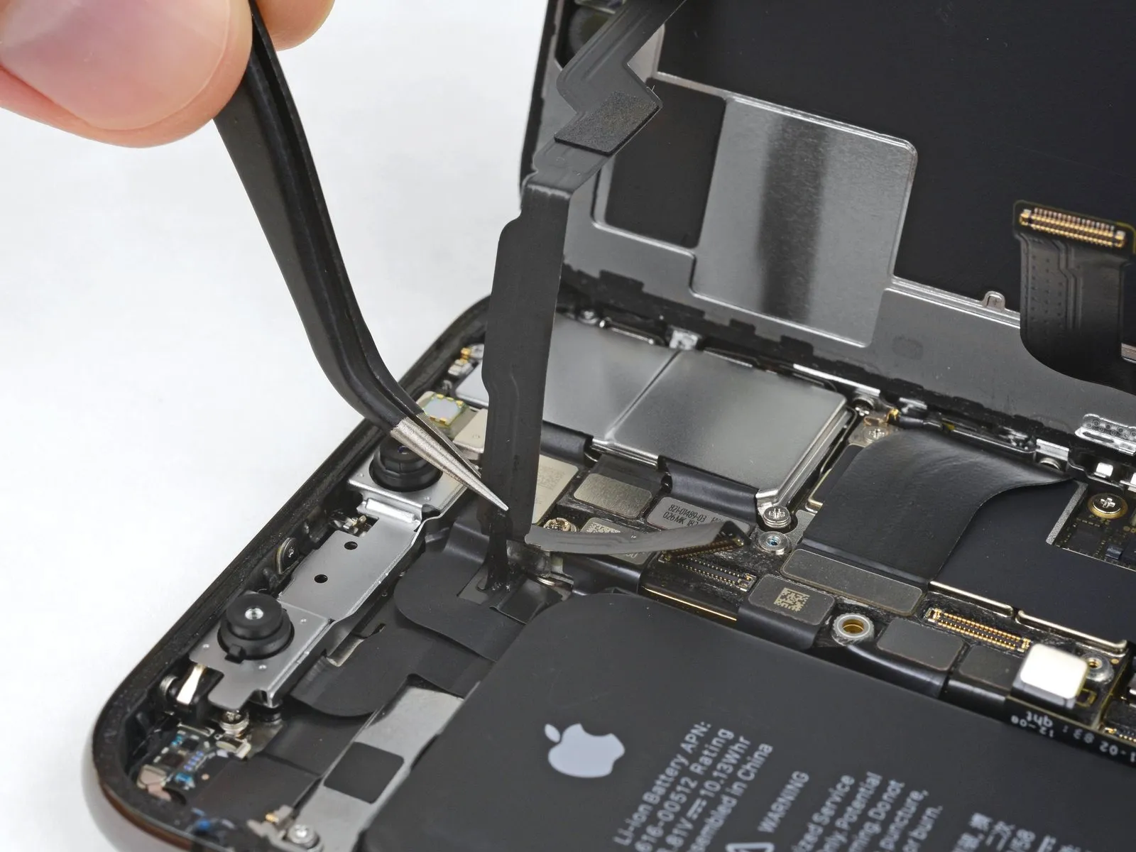
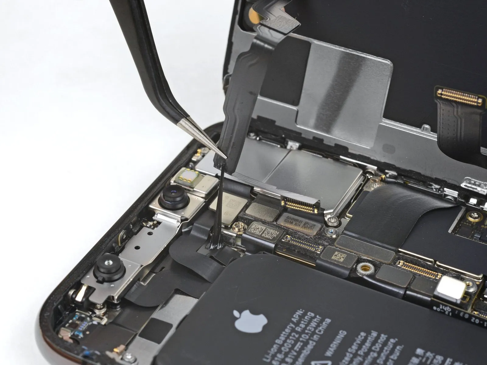
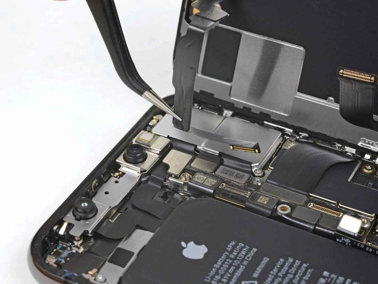
- Gently raise the cable to release the adhesive bond.
Step 23
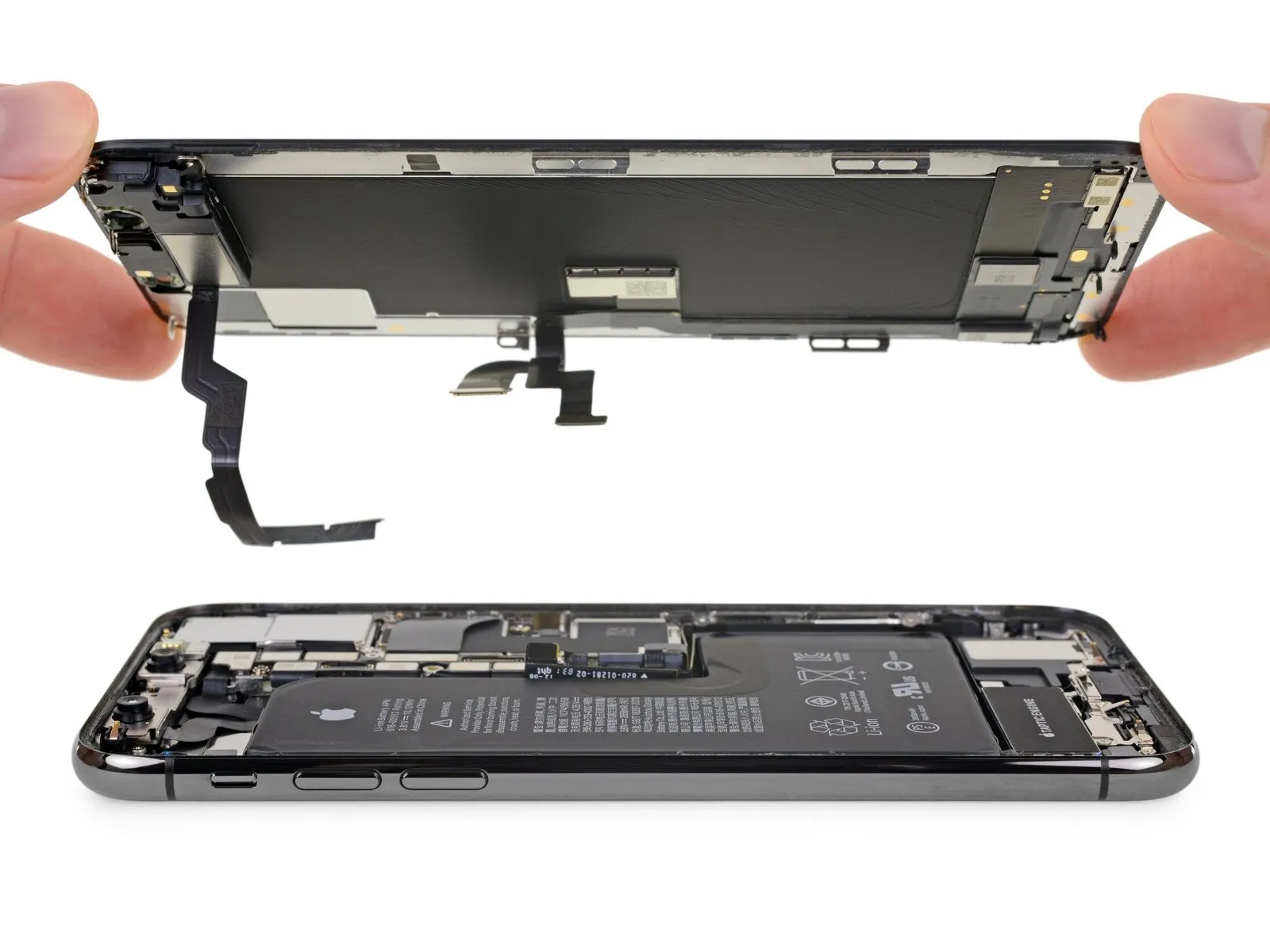
- If you intend to substitute the waterproof sealant bordering the display's perimeter during reinstallation, temporarily halt operations at this juncture.
Step 24 | Earpiece Speaker and Front Sensor Assembly


- Important: The screw's position is obscured by the tape.
Step 25


- A 1.3-millimeter screw is among those securing the assembly.
- A 1.4-millimeter screw is also used to secure the assembly.
- Additionally, a 1.9-millimeter screw is present.
Step 26


Employing a spudger tool, carefully lift the speaker assembly from its position by inserting the tool beneath the upper border and pivoting it downwards, separating it from the display's top edge.
The speaker is connected by a delicate flex cable; exercise caution to prevent any undue stress or potential harm to this cable.
Step 27

Step 28


Apply a slight rotational force to disengage the microphone, exercising caution to prevent undue stress or harm to the flexible cable.
Should separation prove challenging, employ the pointed tip of a spudger to complete the detachment of the microphone from its recess in the front panel; if resistance persists, consider applying additional heat.
Step 29


- Commencing with the left side, insert a separating tool beneath the flexible cable and also beneath the proximity sensor and flood illuminator module assembly.
- Employing a gentle wiggling motion, elevate the module to disengage it from its corresponding recess within the front panel.
- Maintaining access is facilitated by temporarily lifting and repositioning the speaker; however, exercise caution to avoid stressing the delicate flexible cable during this process.
Step 30


- Employing tweezers, gently manipulate the ambient light sensor to dislodge it from its corresponding recess within the display panel.
- Should the sensor resist separation after a brief period of manipulation, increase the applied heat and attempt the release process once more.
- The sensor is connected to the broader sensor assembly through an exceptionally delicate flex cable; exercise caution to prevent undue stress or harm to this cable.
Step 31


- Following complete removal of the ambient light sensor, as depicted in the initial image, proceed to the subsequent instructions.
- Should the white diffuser strip become separated and remain lodged within the display assembly, as illustrated in the second photograph, employ a slender blade or prying instrument to meticulously extract it from the top edge. Applying warmth beforehand might facilitate this process.
- For reassembly, initially position the diffuser within the display, ensuring correct orientation; the front surface is visible in the first image, while the rear surface is shown in the third image.
- Subsequently, place the ambient light sensor atop the diffuser; maintain its position while fastening the screws that secure the earpiece/sensor assembly. Once these screws are fully tightened, the sensor will remain securely positioned and function as intended.
Step 32


- Detach the earpiece speaker and front sensor assembly as a single unit.
- When putting everything back together, verify the alignment of the dark-colored plastic component that houses these parts:
A sensor that detects closeness.
A light source used to illuminate the area being viewed. - Ensure this module's placement allows unobstructed operation of these components, free from any adhesive interference.